
Contactless Thin-Layered Torque Sensor Module with Fully-digital
Signal Processing Circuit
Chi-Ting Yeh
1
, Nan-Chyuan Tsai
1
, Hsin-Lin Chiu
1
and Chung-Yang Sue
2
1
Department of Mechanical Engineering, National Cheng Kung University, 70101, Tainan City, Taiwan
2
Industrial Technology Research Institute, 734, Tainan City, Taiwan
Keywords: Torque Sensor, Orange-slice-alike Flexible Body, Fully-digital Signal Processing Circuit, Optical Grating.
Abstract: A contactless thin-layered torque sensor with fully-digital signal processing circuit is proposed in this work.
The mechanical structure of the torque sensor is an orange-slice-alike flexible body. Two links, beforehand
aligned, with B/W stripes play the role of optical grating by resolution
1
as no any torque applied to the
shaft. As long as the orange-slice-alike flexible body, sandwiched by the aforesaid links, is subject to an
external torque applied, a twisted angle is induced between the two thin photo-grating discs. Two sets of
photo detector cooperate with the two discs with optical gratings to generate two pulse sequences.
Therefore, a time delay between these two pulse sequences can be acquired as long as the shaft is twisted
by a torque. A counter IC is employed to quantify this time delay in terms of the torque applied, and the
time period, in terms of rotational speed of shaft. One of merits of the proposed torque sensor is: real-time
measurement on torque applied becomes feasible even if the shaft, subject to external torque, is rotating at
high speed. Another advantage of the fully-digital signal processing circuit is: no need to conduct A/D
conversion and free of noise, cross-talk and EMI (Electromagnetic Interference).
1 INTRODUCTION
The operation principle of a torque sensor is to
quantify the angular deformation of a shaft which is
subject to an external torque if the torsional stiffness
is known beforehand. Torque sensors are often
applied to monitor the input/output torques for a
wide variety of industries such as numerous types of
motors, generators, engines, torque wrenches and etc.
No doubt the role of torque sensor is pretty
significant in control/servo systems as well.
The traditional torque sensors apply strain
gauges to derive the torque exerted on the shaft. The
induced voltage signals are exported by the
embedded carbon brushes and the slip ring at the
strain gauge unit. The type mentioned above is so
called “contact-type”. As well known, it has many
shortcomings such as the undesired abrasion caused
by the relative rotation between carbon brush and
slip ring so that the lifespan of torque sensor is short
and the measurement error is high. Therefore, non-
contact type torque sensors are developed afterwards.
In addition, the shape of rotary torque transducer
is usually and popularly designed to be of long
cylinder due to consideration of easier mass
production. However, after being installed with
robot arms, the overall length of the resulted
equivalent robot arm is much increased. This results
in more control complication and more room
required. Therefore, the tendency of new design is
trying its best to reduce the axial thickness of
cylindrical torque sensors. Nevertheless, the current
commercial rotary torque sensors with thin thickness
are mostly of contact-type. In other words, their
performance is determined quite much by the
corresponding electronic facilities, circuit and
temperature correction technique. Besides, the
output signals of rotary thin torque sensors are all
analog. It leads to another serious concern: electric
interference such as EMI, cross-talk and noise.
In recent years, various researches regarding
torque sensors were proposed. An optical type of
torque sensor applied for the arm of humanoid robot
was designed by Tsetserukou et al. (Tsetserukou,
2006). Another optical torque sensor using
compliant suspension to suppress measurement
crosstalk is presented by Kaminaga et al. (Kaminaga,
2011). Though their torque sensor is of non-contact,
the corresponding output signal is still analog. On
the other hand, multi-axes torque sensors gradually
450
Yeh C., Tsai N., Chiu H. and Sue C..
Contactless Thin-Layered Torque Sensor Module with Fully-digital Signal Processing Circuit.
DOI: 10.5220/0005017004500458
In Proceedings of the 11th International Conference on Informatics in Control, Automation and Robotics (ICINCO-2014), pages 450-458
ISBN: 978-989-758-039-0
Copyright
c
2014 SCITEPRESS (Science and Technology Publications, Lda.)

attract intensive attentions. A six-axes wrist
force/moment sensor was proposed by Kim applied
for an intelligent robot (Kim, 2007). Liang et al.
presented another type of six-dimensional wrist
force/torque for five-axes parallel machine tool
(Liang, 2010). In addition to optical torque sensors,
a six-axis capacitive-type force-torque sensor is
designed and realized to measure the power transfer
between the human body and the environment
(Brookhuis, 2014). Besides, a capacitor-type torque
sensor, capable to measure the full angular torque
range, is proposed to apply upon magnetic
anisotropies (Rigue, 2012). Unfortunately, the
aforesaid torque sensors are not applicable to rotary
shafts, particularly for high speed mode.
To count for the shortcomings of the torque
sensors discussed above, a contactless thin-layered
torque sensor with fully-digital signal processing
circuit is hence proposed in this work. The proposed
torque sensor possesses a lot of merits such as low
cost, free maintenance, thin thickness, light weight,
adaptive to be applied to high-speed rotors, and no
signal interference at all. Compared with the
traditional torque sensors, the advantages of the
proposed sensor are listed in Table 1.
This proposed digital torque sensor can be
employed for numerous applications such as
machine tools, robot arms, spindles of power tools,
washing machines and etc. Due to its merits of free
contact and noise, its measurement precision can be
retained all the time even under serious
contamination environments.
Table 1: Comparison between traditional and proposed
torque sensors.
Compared with
analog torque sensors
Compared with
rotary (brush
embedded) torque
sensor
Lower cost
Can operate in high
speed
No signal interference No brush wear
No need to compensate
temperature correction
No noise out of carbon
brush
Lower demand on the
performance
requirements of
associated photo
reflectors
Longer lifespan and
more reliability
2 DESIGN OF CONTACTLESS
THIN-LAYERED TORQUE
SENSOR
To design a torque sensor applied to robot arms with
high-speed shafts, it is expected to meet a few goals:
(i) thin along axial direction, (ii) able to operate
under high-speed rotation mode, (iii) able to real-
time measure the torque exerted on the shaft, with
no considerable time delay.
2.1 Thin and Flexible Mechanical
Structure
The profile and the parameters of proposed thin
orange-slice-alike flexible body are shown in Figure
1. The basic design concept of the mechanical
structure is to take advantage of elastic deformation
of the metal texture to reflect the exerted torque.
One outer ring and six palm anchors are combined to
construct the main part of the orange-slice-alike
flexible body. To enhance more sensitivity to the
exerted torque, the outer ring and the palm anchors
are radially connected by spokes so that the cross-
section of the mechanical structure therefore looks
like an orange slice. The parameters and dimensions
of the spokes can be obtained by consideration of the
overall volume of the torque sensor as small as
possible but its precision and resolution as high as
possible. Aside, a few screw holes are made on the
outer ring and palm anchors for connecting the
associated linkers and the orange-slice-alike flexible
body. If an external torque was applied to this
mechanical structure, the twelve spokes would be
twisted at the same time such that the deformations
of twelve spokes would together result in a relative
angular displacement between the outer ring and
palm anchors. Based on the assumption that the
torsional stiffness of the orange-slice-alike flexible
body is constant, the applied torque can be
quantified via the evaluation of this induced twisted
angle. Compared with the design of non-coplanar
flexible structure (Renaud, 2009), the sensitivity and
reliability of proposed orange-slice-alike flexible
body by authors is evidently much superior.
How to design the profile of the orange-slice-
alike flexible body directly affects the performance
of the resulted torque sensor, including the
achievable range of measurement, the rotational
speed span compatible with the torque sensor
equipped (operation bandwidth), resolution, linearity
and so on. Hence, firstly the mechanical design is
focused on: the orange-slice-alike flexible body can
ContactlessThin-LayeredTorqueSensorModulewithFully-digitalSignalProcessingCircuit
451

Figure 1: Profile of Thin Orange-slice-alike Flexible Body
(Dimensions in mm).
result in a twisted angle as large as possible but still
it has to be fully secure by ensurance of sufficient
fatigue strength. By assuming spokes of the orange-
slice-alike flexible body are cantilever beams, the
relation between the bending moment and the
resulted maximum normal stress at the free end of
the cantilever spoke is as follows:
strengthfatigue
Nbt
M
I
Mc
6
2
max
(1)
where
N
,
b
, and
t
are the numbers, width,
thickness of the spokes respectively.
M
is
maximum torque applied to the orange-slice-alike
flexible body.
I
is the moment of inertia of
rectangular cross-sectional area of the spoke.
12
3
bt
I
(2)
The fatigue strength depends on the material chosen.
Once the material of orange-slice-alike flexible body
is chosen,
2
Nbt
can be considered as a constant,
.
.
2
constNbt
(3)
On the other hand, the spring constant of the orange-
slice-alike flexible body can be derived as follows
(Shams, 2012):
)
331331
(
/)
331
)(
331
(4
3
2
2
2
22
3
1
2
2
11
3
2
2
2
22
3
1
2
2
11
l
r
l
r
ll
r
l
r
l
l
r
l
r
ll
r
l
r
l
NEIk
s
(4)
where
1
l
and
2
l
are the spoke lengths for connecting
the palm anchor and the outer ring to the geometric
center of mechanical structure respectively,
E
modulus of elasticity of material, and
r
inner radius
of the orange-slice-alike flexible body. By replacing
length-related terms by equivalent length,
e
L
, the
spring constant can be simplified as follows:
312
4
11
3
M
L
t
EL
bt
NEk
ees
(5)
The product of the twisted angle and thickness of
spokes can be obtained:
.
3
1
Const
LE
M
t
e
(6)
The larger
in Eq. (6), the smaller
t
has to be.
Once
t
is settled, the length of spokes can be
determined simultaneously.
2.2 Computer Simulations of
Orange-slice-alike Flexible Body
Subject to Torque
Aluminium Alloy 7075-T6 is chosen as the material
of the orange-slice-alike flexible body. The fatigue
strength of 7075-T6 is 159MPa (Was, 1981). The
relation between the twisted angle of orange-slice-
alike flexible body and the applied torque is
developed by the commercial software ANSYS and
shown in Figure 2. The case in Figure 2 is a 4 N-m
torque applied on the orange-slice-alike flexible
body under rotational speed being 20000 RPM. The
maximum stress, shown in Figure 2, is about 90MPa.
It is far below the fatigue strength of 7075-T6 (about
57%). Besides, the resulted twisted angle with
respect to the applied torque 4 N-m is shown in
Figure 3. It is evident to find the property of high
linearity in terms of twisted angle to torque. The
resulted twisted angle of the torque sensor is
042.1
as a torque 4 N-m is applied. Finally, the photograph
of the corresponding torque sensor successfully
manufactured is shown in Figure 4.
2.3 Optical Grating and Light Receiver
To realize the proposed torque sensor applied to
high-speed shafts, a couple of reflective photo
detectors and the associated reflectors with
black/white strips, shown in Figure 5, are equipped.
As the light by light-emitting element shoots onto
the white strips on reflector, shown in Figure 5(a),
the light will be reflected to the photo receiver and
hence an output voltage is generated by the photo
detector. On the contrary, no output signal is
generated if the light by light-emitting element
ICINCO2014-11thInternationalConferenceonInformaticsinControl,AutomationandRobotics
452
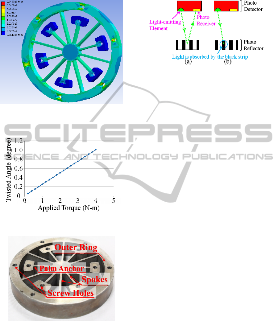
Figure 2: Stress Distribution on Orange-slice-alike flexible
body by Torque: 4 N-m and Speed: 20000 RPM (Unit of
Stress: Pa).
Figure 3: Relation between Twisted Angle and Applied
Torque.
Figure 4: Photograph of Orange-slice-alike flexible body.
shoots onto the black strips, shown in Figure 5(b).
The pulse-type output signal is therefore generated
in sequence by the photo detectors all the time as the
shaft is either still or rotating at high speed. For
simplicity, the upper module and lower module
shown in Figure 5 will be hereafter called as “photo
detector” and “photo reflector” respectively.
Figure 5: Schematic Diagram of Reflective Photo Detector.
As the shaft is rotating, the orange-slice-alike
flexible body and two photo reflector units are
rotating as well because they are all fixed and
attached to the shaft. Instead, the reflective photo
detectors are not rotating at all because they are
apart and completely separated away from the shaft.
By any one of the photo detectors, the rotational
speed of the shaft can be obtained since it plays the
role of encoder as well. It is noted that beforehand
these two photo reflectors have to be completely
aligned under the circumstance: no any torque
applied. Figure 6(a) is referred to this case: no
torque applied. Most importantly, the trigger signals
to these two photo detectors, to generate the pulse
sequences, have to be synchronized all the time.
Once the orange-slice-alike flexible body is
deformed by external torque, the two reflectors will
be also twisted and an angle, i.e., the relative angular
displacement, is induced. Figure 6(b) is referred to
the case of an external torque applied. Therefore,
the output signals out of the two corresponding
reflective photo detectors will present a time
difference or called time delay. This time delay can
be utilized to quantify the torque applied to the shaft.
The photograph of the entire contactless thin-layered
torque sensor unit mounted to the shaft is shown in
Figure 7.
3 FULLY-DIGITAL
SIGNAL-PROCESSING
CIRCUIT
The associated circuit to comply with the photo
detectors is nothing but a type of fully-digital
counter so that almost no signal interference is
involved. The principle of counting is shown in
Figure 8. The counter IC is reset and immediately
starts to count after receiving the trigger signal at
PIN 11 from Reflective Photo Detector #1. As the
D-flip-flops receives the trigger signal at PIN 9 from
Reflective Photo Detector #2, a number of counts
ContactlessThin-LayeredTorqueSensorModulewithFully-digitalSignalProcessingCircuit
453
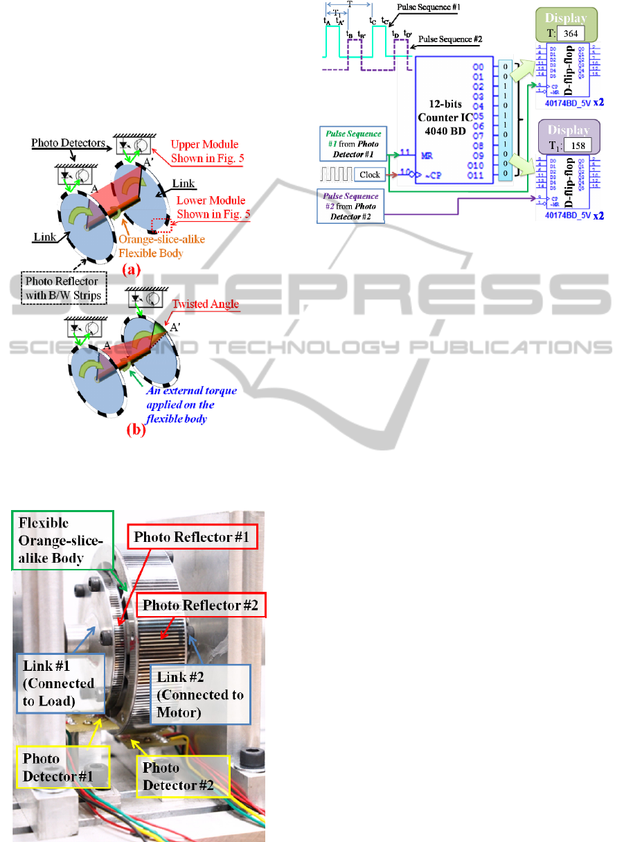
will be exported to the display. It is noted that two
key parameters,
T
and
1
T
, are named as “time
period” and “time delay” respectively. By physical
meanings,
T
is determined by the rotational speed
of shaft while
1
T
by how much the torque is applied
onto the shaft. That is, the larger torque, the larger
1
T
.
Figure 6: Schematic Diagram of Photo Detectors and
Photo Reflectors (a): no torque applied; (b): an external
torque applied.
Figure 7: Photograph of Contactless Thin Torque Sensor.
Figure 8: Schematic Diagram of Counter and Triggers.
The potential flaws by the signal-processing circuit
without flip-flops are:
(a) : Missed count due to overlap of two pulse
sequences.
(b) : The count numbers are running too fast to
be instantly picked up.
How to overcome these two flaws is described in
following sections.
3.1 Flaw #1: Missed Count Due to
Overlap of Two Pulse Sequences
The duty cycle of either pulse sequence is
determined by the rotation speed of shaft and the
width of B/W strip on the photo reflector. Normally,
the two pulse sequences, Pulse sequence #1 and
Pulse Sequence #2, are completely decoupled and
shown in Figure 9(a). However, once the rotation
speed of shaft is low and the width of B/W strip is
relatively larger, the phenomenon of overlapped
sequences occurs and is shown in Figure 9(b). The
counter IC is triggered to start to count by PIN 11
which is defined as “high active”. That is, during
the time interval,
AA
tt
~
, the counter IC is under
the operation of triggering until
A
t
. Unfortunately,
if the applied torque is relatively smaller, Pulse
Sequence #2 is coming in just during this time
interval,
AA
tt
~
. This results in ignorance of the
event which occurs at Instant
B
t by counter IC so
that the expected count for
1
T
(i.e., from
A
t
to
B
t
) is
missed at all. To solve this overlap problem, an
inductor (
R
L ) is inserted and shown in Figure 10, in
parallel to Pulse Sequence #1. The reason is stated
as follows. Since an inductor is like a very-low-pass
filter, at the instant
A
t
(i.e., sudden change from low
ICINCO2014-11thInternationalConferenceonInformaticsinControl,AutomationandRobotics
454
to high), the inductor is near “open” (i.e., cross-
voltage to be high) but approaches to be near “close”
(i.e., cross-voltage to be zero) as time goes away
from instant
A
t
due to Pulse Sequence #1 being
kept to be flat from
A
t
to
B
t
. The cross-voltage of
the inductor is shown in Figure 9(c) and 9(d),
compared with the original Pulse Sequence #1 in
Figure 9(a) and 9(b), to which no any inductor
inserted. That is, the impact of overlap between
Pulse Sequence #1 and Pulse Sequence #2 is
greatly reduced.
Figure 9: Effect by Additional Inductor Inserted to
Counter Circuit (a) w/o Overlap and w/o Inductor Inserted;
(b) with Overlap but w/o Inductor Inserted; (c) w/o
Overlap but with Inductor Inserted; (d) with Overlap and
with Inductor Inserted.
Figure 10: DSP Circuit for Computer Simulations.
3.2 Flaw #2: the Count Numbers Are
Running Too Fast to Be Instantly
Picked up
Since the data at count register is running very fast
as long as the counter IC has been triggered, how to
real-time pick up the current-time count number to
reflect the current-time torque applied has to be
figured out. To solve this problem due to extremely
dynamical data change of torque measurements, 4
units of D-flip-flop, shown in Figure 10, are added
to the counter DSP circuit. Two of them (i.e., #1
and #4) are for
T
while the other two (i.e., #2 and
#3) for
1
T
. The two flip-flops are employed to
comply with the 12-digital counter IC since each D-
flip-flop IC 40174BD is of 6-digit. That is, the D-
flip-flop is operating like a buffer and temporary
storage of the current-time count number.
3.3 Computer Simulations of
Fully-digital Signal Processing
Circuit
Assume the torque sensor has the property of linear
stiffness for the orange-slice-alike flexible body. It
would be twisted by one degree (i.e.,
1
) if a torque
4 N-m was applied to the shaft. The computer
simulation results for the DSP circuit as the shaft is
rotating at 10000 RPM are shown in Figure 11. The
count number, with respect to
1
T
, is 82 as a torque 4
N-m is applied to the shaft. In comparison, if the
torque is reduced by 50%, i.e., 2 N-m, the
corresponding count number is reduced to 40. It is
observed that, the error of count is about 5% at high-
speed rotation. On the other hand, if the rotation
speed of shaft is reduced to 2000 RPM, the
corresponding simulation results are shown in
Figure 12. In Figure 12(a), the count number, with
respect to
1
T
, is 384 as a 4 N-m external torque
applied to the shaft. The count number is reduced to
192, shown in Figure 12(b), as the applied torque is
reduced by 50%. There is no measurement error
under low speed rotation. It is concluded that in
order to improve the resolution and accuracy at high
rotational speed, the physical quantity of the
inductor connected in parallel to Pulse Sequence #1,
R
L
, has to be chosen properly or the associated
circuit has to be equipped with a counter IC
facilitated with a higher-frequency clock.
4 EXPERIMENTAL RESULTS
The experimental setup of the contactless thin-
layered torque sensor is shown in Figure 13. A set
of gap sensor, Model LK-031 by Keyence
Instrumentation Corporation, is employed to acquire
the angular displacements (i.e., twisted angles) of
ContactlessThin-LayeredTorqueSensorModulewithFully-digitalSignalProcessingCircuit
455
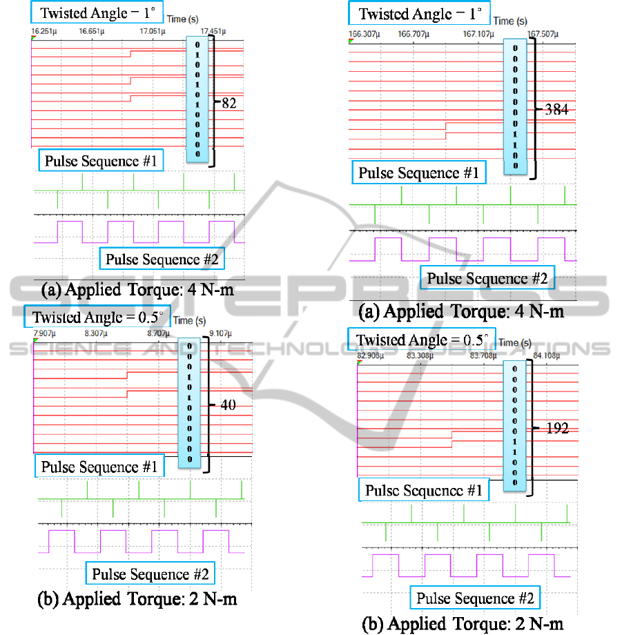
Figure 11: Count Numbers Versus Twisted Angles as
Shaft is Rotating at 10000 RPM.
the orange-slice-alike flexible body for calibration
propose, a high-precision torque sensor, Model
4520A by Kistler Instrument Corporation, is
employed to acquire the applied torque to be
compared with the proposed contactless thin-layered
torque sensor. Besides, one compressed air brake,
Model AHB-6 by Magtrol Instrumentation
Corporation, is applied to reduced the speed of the
shaft and protect the proposed torque sensor. The
experiments are undertaken under the interface
module cDAQ-8178 by NI and the environment by
Labview. The contactless thin-layered torque sensor
Figure 12: Count Numbers Versus Twisted Angles as
Shaft is Rotating at 2000 RPM.
is examined for its hysteresis characteristics by
applying torque in ascending/descending manner.
The angular displacement and the applied torque are
recorded by Labview to the storage of computer.
The graphic program by Labview to record the
applied torque on the shaft and corresponding
twisted angle is shown in Figure 14. The linear
displacement,
D
d
, obtained by laser displacement
sensor has already been converted into the twisted
angle,
t
, of the orange-slice-alike flexible body by
ICINCO2014-11thInternationalConferenceonInformaticsinControl,AutomationandRobotics
456
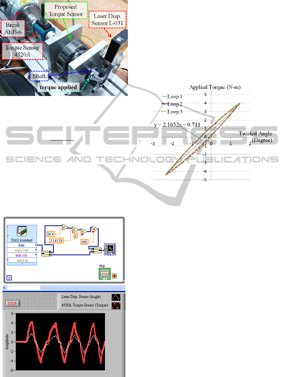
Figure 13: Experimental Setup for Proposed Torque
Sensor.
the following rotation between
D
d
and
t
:
P
D
t
r
d
**2
360*
(7)
where
t
is twisted angle of the orange-slice-alike
flexible body.
D
d is the linear displacement
measured by the laser displacement sensor.
mmr
P
4.58
is the distance between the shaft and
the laser displacement sensor. The real-time
simulations of applied torque and twisted angle are
shown at the bottom of Figure 14.
Figure 14: Graphic Simulation Program by Labview to
Record Torque and Twisted Angle.
The hysteresis loop is shown in Figure 15. It is
observed that the proposed torque sensor is with
high linearity verified by the intensive experiments
undertaken. However, the twisted angles by
experiments are a little larger than those by
computer simulations described in Section 2.2. This
might be caused by the undesired deformation of the
linker. At last, the repeatability of the proposed
torque sensor in terms of applied torque to resulted
counts by the DSP circuit, denoted by Loop 1,
Loop2 and Loop 3, is pretty superior.
Figure 15: Hysteresis Loop of Proposed Torque Sensor.
5 CONCLUSIONS
A contactless thin-layered torque sensor with fully-
digital signal processing circuit is proposed. The
measurement range is up to torque 4 N-m and the
rotational speed of shaft, compatible to the proposed
torque sensor, up to 20000 RPM. The overall axial
thickness of the torque sensor unit is only 42.6 mm.
Compared with traditional torque sensors, the
advantages of the proposed torque sensor are: (i) no
need of analog/digital conversion for torque
measurement, (ii) free of noise interference, (iii) due
to its thin axial thickness, it is highly applicable for
robot arms or multi-axes machine tools, (iv) it is also
applicable for high speed shafts, and (v) it has the
properties of high linearity in terms of applied
torque with respect to twisted angle of the orange
slice-alike flexible body, and superior repeatability
in terms of torque measurement.
ACKNOWLEDGEMENTS
This research was partially supported by Industrial
Technology Research Institute (Taiwan). The
ContactlessThin-LayeredTorqueSensorModulewithFully-digitalSignalProcessingCircuit
457

authors would like to express their appreciation.
REFERENCES
Tsetserukou, D., Tadakuma, R., Kajimoto, H., Tachi, S.,
2006. Optical torque sensors for implementation of
local impedance control of the arm of humanoid robot,
2006 IEEE Int. Conf. on Rob. and Auto., pp. 1674–
1679.
Kaminaga, H., Odanaka, K., Kawakami, T., Nakamura, T.,
2011. Measurement Crosstalk Elimination of Torque
Encoder Using Selectively Compliant Suspension,
2011 IEEE Int. Conf. on Rob. and Auto., 2011.
Kim, G.-S., 2007. Design of a six-axis wrist force/moment
sensor using FEM and its fabrication for an intelligent
robot, Sensors and Actuators A: Physical 133(1), pp.
27–34.
Liang, Q., Zhang, D., Song Q., Ge, Y., Cao, H., 2010.
Design and fabrication of a sixdimensional wrist
force/torque sensor based on E-type membranes
compared to cross beams, Measurement 43, pp. 1702–
1719.
Brookhuis, R.A., Droogendijk, H., De Boer, M.J., Sanders,
R.G.P., Lammerink, T.S.J., Wiegerink, R.J., Krijnen,
G.J.M., 2014. Six-axis force–torque sensor with a
large range for biomechanical applications, Journal of
Micromechanics and Microengineering 24(3), Paper
No. 035015.
Rigue, J., Chrischon, D., De Andrade, A. M. H., Carara, M,
2012. A torque magnetometer for thin films
applications, Journal of Magnetism and Magnetic
Materials, 324(8), pp. 1561-1564.
Renaud, P., Michel, M., 2009. Kinematic analysis for a
novel design of MRI-compatible torque sensor, 2009
IEEE/RSJ Int. Conf. on Int. Rob. and Sys., pp. 2640-
2646.
Shams, S., Lee, J.-Y., Han, C., 2012. Compact and
lightweight optical torque sensor for robots with
increased range, Sensors and Actuators A: Physical,
173, pp. 81-89.
Was, G. S., Pelloux R. M., Frabolot, M. C., 1981. Effect
of shot peening methods on the fatigue behavior of
alloy 7075-T6, 1th Int. Conf. on Shot Peening, pp.
445-452.
ICINCO2014-11thInternationalConferenceonInformaticsinControl,AutomationandRobotics
458
