
Real-time Super Resolution Equipment for 8K Video
Seiichi Gohshi
Kogakuin University, 1-24-2 Nishi-Shinjuku, Shinjuku-ku, Tokyo, 163-8677, Japan
Keywords:
Super Resolution, 8K, 4K, Real-time, Image Enhancement.
Abstract:
Resolution is one of the most important things when assessing image quality, and image quality improves in
proportion to resolution. Super Resolution (SR) is a resolution improving technology that is different from
conventional image enhancement methods. SR methods, of which there are many, typically have complex
algorithms that involve iterations, and it is not easy to apply them to video running in real time at 50 or 60
frames a second; i.e., each frame would have to be processed in 20 ms (50 Hz) or 16.7 ms (60 Hz). In this
paper, a simple form of SR that uses non-linear signal processing is proposed to cope with the difficulties in
real-time processing. Real-time hardware equipped with an FPGA (Field Programmable Gate Array) for 4K
and 8K video is shown and its SR capability is discussed.
1 INTRODUCTION
HDTV digital broadcasting started at the beginning of
this century and since has spread all over the world.
The resolution of HDTV is 1920 × 1080, five times
higher than analogue TV systems such as PAL, SE-
CAM, and NTSC. Although CRT displays were in the
mainstream at the beginning of HDTV broadcasting,
LCDs have become the common these days. LCDs
are cost effective, lightweight, and high in resolution.
Currently, almost all TV and computer displays are
LCDs. If we view digital HDTV broadcasting as
a paradigm shift, the spread of LCDs is surely an-
other one. Moreover, the resolution of LCDs has been
growing dramatically. In fact, 4K displays that have
four times higher resolution than HDTV are now on
the market. The problem is that there is no 4K broad-
casting. To fill in for the dearth of 4K content, at-
tempts are being made to up-convert HDTV content
to 4K resolution and show it on 4K displays. Here,
the resolution of 4K is 3840 × 2160, so the HDTV
content has to be enlarged by double horizontally and
vertically.
Such enlargements always cause blur. Figure 1
is an enlargement made by cropping the white rect-
angle area in Figure 2 and blowing it up 1.3 times.
As one can see, it is very blurry compared with the
white rectangular area in Figure 2. This simple ex-
ample illustrates that images are easily degraded by
enlargement and suggests that up-converted 4K con-
tent from HDTV would look even worse, as the en-
largement factor would be 2, not 1.3. Moreover, it is
doubtful that Enhancer (Schreiber, 1970; Lee, 1980;
Pratt, 2001) would be a sufficient means of enhanc-
ing such up-converted content. New technologies are
needed to deal with this problem.
Super Resolution (SR) is a technology that cre-
ates a high-resolution image from low-resolution ones
(Park et al., 2003; Farsiu et al., 2004; Eekeren et al.,
2010; Houa et al., 2011; Protter et al., 2009; Panda et
al., 2011; Matsumoto and Ida, 2010). The keyword
phrase ”Super resolution” gets about 190 million hits
on Google. Indeed, there are many SR proposals, but
most of them are complex algorithms involving many
iterations. Such algorithms are almost impossible to
into real-time hardware.
Figure 1: Enlarged image.
Figure 2: Original image.
149
Gohshi S..
Real-time Super Resolution Equipment for 8K Video.
DOI: 10.5220/0005014901490156
In Proceedings of the 11th International Conference on Signal Processing and Multimedia Applications (SIGMAP-2014), pages 149-156
ISBN: 978-989-758-046-8
Copyright
c
2014 SCITEPRESS (Science and Technology Publications, Lda.)
SR for TV should have low delay. In live
news broadcasts especially, conversations between
announcers in the TV studio and persons at the report-
ing point tend to be affected by delays. For viewers,
the superimposed time is not accurate on a TV screen
if the delay is longer than 60 seconds. For these rea-
sons, complex SR algorithms with iterations cannot
be used in TV systems.
Non-linear signal processing (NLSP) has been
proposed as an alternative to the conventional image
enhancement methods (Gohshi and Echizen, 2013),
and it has several advantages compared with them.
Since it does not use iterations or frame memories,
it is sufficiently lightweight to be installed in an
FPGA (Field Programmable Gate Array) for real-
time video processing. Furthermore, it can create
frequency elements that are higher than those of the
original image, as has been proven by performing
two-dimensional fast Fourier transform (2D-FFT) re-
sults(FFTs (Gohshi and Echizen, 2013). Although
there is real-time hardware that can process enlarged
images (Gohshi et al., 2013), its FPGA has a maxi-
mum speed of 30 Hz, far less than 60 Hz or 50 Hz
of video. In addition, certain frequency elements are
emphasized too much. In this paper, we present new
real-time NLSP hardware that is free of these prob-
lems.
Figure 3: NLSP algorithm.
Horizontal
NLSP
Input
Vertical
NLSP
Output
Figure 4: Sequential NLSP.
2 PREVIOUS RESEARCH ON
NLSP
The basic idea of NLSP is like that of the one-
dimensional signal processing shown in Figure 3
(Gohshi and Echizen, 2013). The input is distributed
π
π
-
π
-
π
Figure 5: 2D image spectra.
π
π
-
π
-
π
Figure 6: Enhanced areas in 2D.
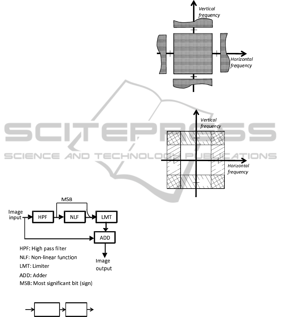
to two blocks. The upper path creates high-frequency
elements that the original image does not have as fol-
lows. The original image is processed with a high
pass filter (HPF) to detect edges. The output of the
HPF is edge information that has a sign, i.e., plus
or minus, for each pixel. After the HPF, the edges
are processed with a non-linear function (NLF). If
an even function such as x
2
is used as the NLF, the
sign information is lost. To stop this from happen-
ing, the most significant bit (MSB) is taken from the
edge information before the NLF and restored af-
ter the NLF. Non-linear functions generate harmon-
ics that can create frequency elements that are higher
than those of the original image. NLSP using a num-
ber of non-linear functions should be able to create
high-frequency elements. Here, we propose y = x
2
for plus edges and y = −x
2
for minus edges.
It is well known that images are expanded in a
Fourier series (Mertz and Gray, 1934).Here, we take a
one-dimensional image f(x) to make the explanation
simple. f(x) is expanded as follows.
f(x) =
+N
∑
n=−N
a
n
cos(nω
0
) + b
n
sin(nω
0
) (1)
SIGMAP2014-InternationalConferenceonSignalProcessingandMultimediaApplications
150
Here, ω
0
is the fundamental frequency and N means
a positive integer. The HPF attenuates low-frequency
elements including the zero frequency element (DC).
We denote the output of the HPF by g(x) and it be-
comes as follows.
g(x) =
−M
∑
n=−N
a
n
cos(nω
0
) + b
n
sin(nω
0
)
+
N
∑
n=M
a
n
cos(nω
0
) + b
n
sin(nω
0
) (2)
M is also a positive integer and N > M. The fre-
quency elements from −M to M are eliminated with
the HPF. DC has the largest energy in the images,
and it sometimes causes saturation whereby the im-
ages become either all white or all black. The square
function does not cause saturation by eliminating DC,
and it has the following effect. Edges are represented
with sin(nω
0
) and cos(nω
0
) functions. The square
function generates sin
2
(nω
0
) and cos
2
(nω
0
) from
sin(nω
0
) and cos(nω
0
). sin
2
(nω
0
) and cos
2
(nω
0
)
generate sin2(nω
0
) and cos2(nω
0
).
These NLFs create frequency elements that are
two times higher than the input (Gohshi and Echizen,
2013), and they can be used to double the size of the
images horizontally and vertically, such as in the con-
version from HDTV to 4K TV. It is necessary to apply
NLSP horizontally and vertically (Figure 4), since im-
ages and videos are two-dimensional signals. Com-
puter simulations based on Figure 4 have been pre-
sented (Gohshi and Echizen, 2013) and real-time (30
Hz) hardware based on Figure 4 has been developed
(Gohshi et al., 2013). However, these developments
pointed out two issues. Using the sequential NLSP
shown in Figure 4, specific frequency elements are
processed twice in a two-dimensional frequency do-
main ; this causes artifacts and increases noise. Fig-
ure 5 shows an example in the two-dimensional fre-
quency domain. The horizontal axis is the horizon-
tal frequency, and the vertical axis is the vertical fre-
quency. The origin of the axes is called direct current
(DC) since the frequency of DC is zero. In Figure 5,
the spectra around DC is fully presented. The same
spectra is repeated every 2π and parts of the spectra
from (2π, 0), (−2π, 0), (0, 2π), (0, −2π) are shown. π
on the horizontal axis and the vertical axis in Figure 5
are the horizontal and vertical Nyquist frequencies.
The first issue is degradation of images whose
frequency components are processed twice. Figure
6 shows the areas in the spectra that are processed
by the sequential NLSP shown in Figure 4. The ar-
eas hatched with lines having positive slopes are sub-
jected to the horizontal signal processing, whereas
those areas hatched with lines having negative slopes
are subjected to the vertical signal processing. The
four corner areas are subjected to both horizontal and
vertical signal processing. These corner areas have
both horizontal and vertical high-frequency elements.
Yet by processing these areas twice, the corner areas
are emphasized in excess, and this degrades the video
quality. When dots in an image that have both hor-
izontal and vertical high-frequency elements move,
they cause flicker. The NSLP emphasizes the flick-
ers on the dots and degrades video quality. Noise that
also has both horizontal and vertical high-frequency
elements exists in these corner areas. If these dots that
have both horizontal and vertical high-frequency ele-
ments are processed with NLSP two times, the noise
will be emphasized. Noise always degrades video
quality.
The second issue is the speed of the FPGA. The
FPGA embodying the sequential NLSP shown in Fig-
ure 4 can only work at 30 Hz (Gohshi et al., 2013).
Although this is fast enough to work on 24 Hz movie
content, it is not fast enough for 50 Hz or 60 Hz video
content.
2D-LPF
Horizontal
HPF
Delay
Input
Vertical
HPF
Output
NLF
HPF: High pass filter
NLF: Non-linear function
LMT: Limiter
MSB: Most significant bit
LMT
NLF
LMT
MSB
MSB
Figure 7: Block diagram of real-time hardware.
π
π
-
π
-
π
Figure 8: Characteristics of 2D-LPF.
3 ADVANCED HARDWARE
ALGORITHM
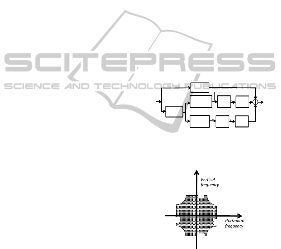
Figure 7 is a block diagram of the real-time video pro-
cessing that is free of the issues discussed in section 2.
The input is distributed to two paths. The bottom line
Real-timeSuperResolutionEquipmentfor8KVideo
151
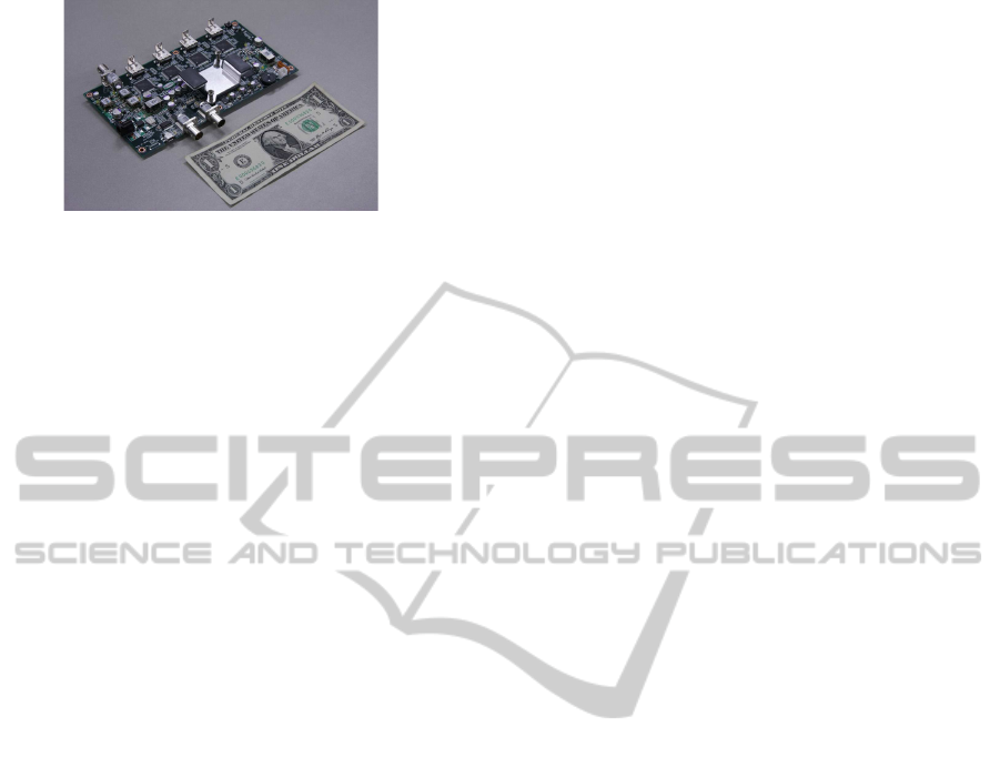
Figure 9: Appearance of real-time hardware.
includes a two-dimensional low pass filter (2D-LPF)
and a parallel NLSP part. The 2D-LPF decreases the
diagonal artifacts, and the parallel signal processing
enables the hardware to operate on 60 Hz moving im-
ages.
The input is distributed to the delay block and the
2D-LPF block. The delay path is the same as the in-
put, and the signal is delayed until the signal process-
ing on the other paths ends. The second path goes
to the 2D-LPF. The 2D-LPF reduces the diagonal is-
sue that is mentioned in section 2. Figure 8 shows
the two-dimensional frequency characteristics of the
2D-LPF. 2D-LPF passes the checker marked area and
eliminates the diagonal frequency elements, i.e., the
four corners shown in Figure 6. It also cuts the noise.
However, the human visual system is not so sensi-
tive to the horizontal and vertical high-frequency ele-
ments, i.e. the four corners shown in Figure 6 (Sakata,
1980). This means these frequency elements in the
NLSP video do not affect the perceived resolution.
Thus, to maintain the original diagonal resolution, the
original diagonal frequency elements are sent through
the delay line and added to the output.
The 2D-LPF eliminates diagonal frequency ele-
ments and splits the signal into two paths. The upper
path is the horizontal NLSP, and the lower path is the
vertical NLSP explained in section 2. The three video
paths are added together at the end to create the NLSP
video.
This parallel signal processing is fast. It reduces
the delay from input to output, as discussed in sec-
tion 1, and it can work at 60 Hz, unlike the sequential
NLSP shown in Figure 4. Figure 9 shows the NLSP
hardware. It up-converts full HDTV (1920× 1080) to
4K (3840× 2160), and it processes the up-converted
4K video with NLSP to increase the resolution at 60
Hz. The NLSP algorithm is installed in the FPGA,
which is located under the heat sink. Although there
are many parts on the circuit board, most of them are
input and output interface devices and electric power
devices.
Figure 10 shows an image processed with the
NLSP hardware shown in Figure 9. Figure 10(a) is
just an enlargement from HDTV to 4K, and it looks
blurry. Figure 10(b) shows the image processed with
NLSP after the enlargement. Its resolution is clearly
better than that of Figure 10(a). Figure 10(c) and
10(d) are the 2D-FFT results of Figure 10(a) and Fig-
ure 10(b). Figure 10(d) has horizontal and vertical
high-frequency elements that Figure 10(c) does not
have. This shows that real-time hardware works and
its function is the same as the simulation result.
4 EFFECT OF 2D-LPF
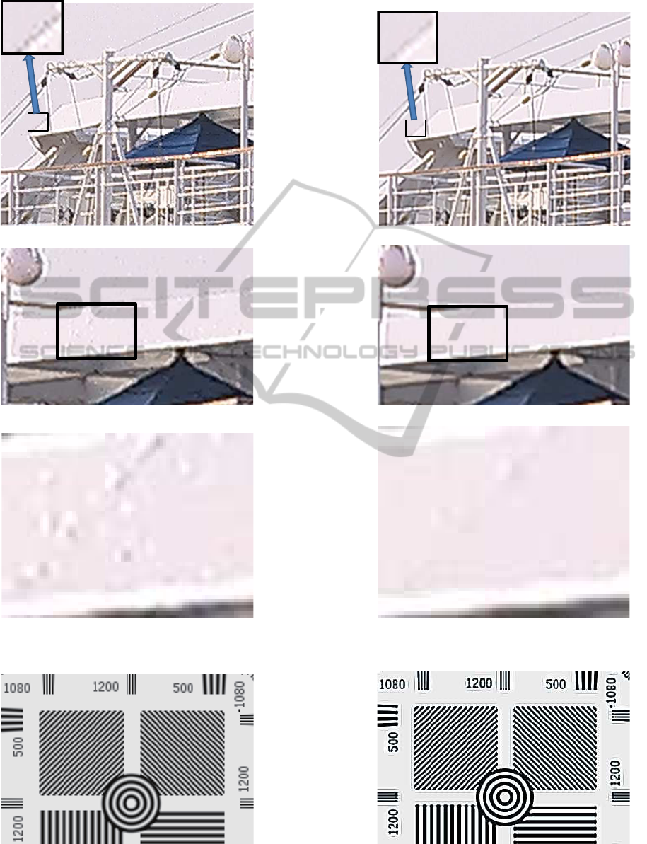
This section describes the effect of the 2D-LPF. Fig-
ure 11(a) shows the NLSP result when the 2D-LPF is
turned off, and Fig. 11(b) shows the result when the
2D-LPF is on. Comparing these two figures, we can
see there are artifacts around slanted lines that are the
diagonal frequency elements (Figure 11(a)). On the
other hand, artifacts are less evident in Figure 11(b).
This means that the 2D-LPF reduces the diagonal fre-
quency elements in Figure 6. Figures 11(c) and 11(d)
show the effect of the 2D-LPF on noise. Figures 11(e)
and 11(f) are enlargementscorresponding to the black
rectangular areas in Figure 11(c) and 11(d). A quick
comparison indicates that Figure 11(f) has less noise.
Slanted lines in an image have both horizontal and
vertical high-frequency elements. In the frequency
domain, slanted lines correspond to two of the four
cross-hatched corners in Figure 6. The lines in the
image that go upwards to the right correspond to the
cross-hatched areas in the first and third quadrants in
Figure 6. The lines in the image that go downwards
toward the right correspond to the cross-hatched areas
in the second and fourth quadrants in Figure 6.
Dot-shaped noise in an image has frequency ele-
ments in the cross-hatched areas of all four quadrants
of Figure 6. The artifacts are reduced because the 2D-
LPF cuts off the frequency elements in these four cor-
ners.
5 FOCUSING EFFECT
Although film cameras have been used in the movie
industry for a long time, most movies are made to-
day with more cost-effective HDTV cameras. These
professional HDTV cameras do not have auto focus
systems that commercial camcorders have. Produc-
tion zoom lenses are used to make TV content since
several scenes are shot in a single take. In these takes,
the camera focus is often changed from one object to
another. It is not easy, even for professional camera
persons, to adjust the focus with a small viewfinder.
SIGMAP2014-InternationalConferenceonSignalProcessingandMultimediaApplications
152
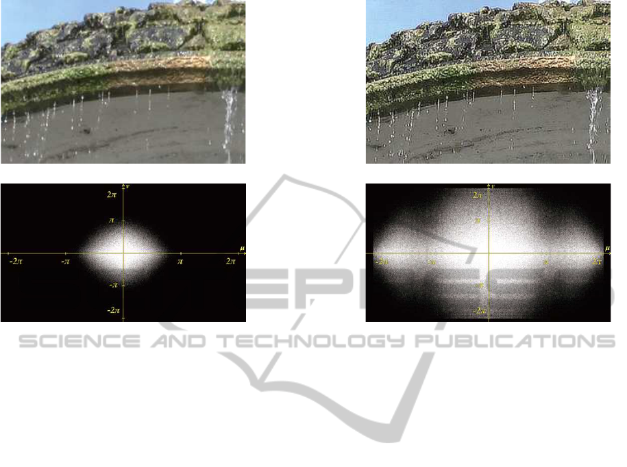
(a) 4K image enlarged from HD (b) 10(a) with NLSP
(c) 2D-FFT result of Figure 10(a) (d) 2D-FFT result of Figure 10(b)
Figure 10: Image processed with real-time NLSP.
Although TV content is often out of focus, we cannot
recognize this on a TV screen because of its relatively
small size. However, if that content were shown on
a large screen of a movie theater, it would appear as
blurry as content shot with a commercial camcorder’s
auto-focus. On the other hand, movies have high res-
olution and appear sharp on large screens in theaters.
That means although TV content and movie content
are shot with HDTV cameras, the difference between
them has to do with the lens focus. Single focus lenses
are used in the movie industry, whereas zoom lenses
are used to make TV content. Thus TV content is
affected by blurring caused by zoom lenses, while
movie productions face the difficulty of performing
multi-focus shots in a single take. These two aspects
of the gout-of-focus problemh are part of the topic
of image restoration, and many ideas have been put
forward to deal with them (Figueiredo and Nowak,
2003)(Pan and Blue, 2011)(Karungaru et al., 2009).
However, the methods presented so far need itera-
tions or parameter adjustments made under certain
hypotheses. It is not easy to use them in practical ap-
plications.
It would be useful if there were a technology that
could focus a shot after it has been made. Here, we
would like to point out that NLSP has a focusing ef-
fect. Figure 12(a) is a blurry image. The original im-
age is crisp (it is part of a test pattern), and it was pro-
cessed with an LPF to make it blurry. Figure 12(b) is
the result of processing Figure 12(a) with the NLSP
hardware. Comparing these figures, we can see that
the resolution of Figure 12(b) is better and the focus
looks adjusted. This effect is due to the character-
istics of NLSP. NLSP can generatee high-frequency
elements that the original image does not have, and
these high-frequency elements have a focusing effect.
6 4K TO 8K UP-CONVERTER
WITH NLSP
8K TV is currently under development. At the mo-
ment the baseband speed of 8K is four times higher
than 4K. At the same time 8K content is very rare.
4K content up-converted to 8K does not have satis-
factory resolution. However, if 4K content could be
up-converted with sufficient resolution, it would be
very useful for 8K development.
The hardware up-converter with NLSP can pro-
cess HDTV and generate 4K in real time. Since the
pixel of 4K is 3820× 2080, it can be divided into four
HDTV video sections. Four 4K video sections can be
generated using the same hardware on each HDTV
section. These four up-converted 4K videos can then
be combined to create 8K video in real time. Figure
13 shows an example of 8K video up-converted from
4K. There are four pairs of images. The column (a)
images are the original 4K frames and the column (b)
ones are double enlargements 8K frames made with
Real-timeSuperResolutionEquipmentfor8KVideo
153
(a) NLSP with 2D-LPF off (b) NLSP with 2D-LPF on
(c) Artifacts without 2D-LPF (d) Artifacts with 2D-LPF
(e) Noise without 2D-LPF (f) Noise with 2D-LPF
Figure 11: Effect of 2D-LPF.
(a) Blurry image (b) Focused image
Figure 12: Focusing effect.
SIGMAP2014-InternationalConferenceonSignalProcessingandMultimediaApplications
154
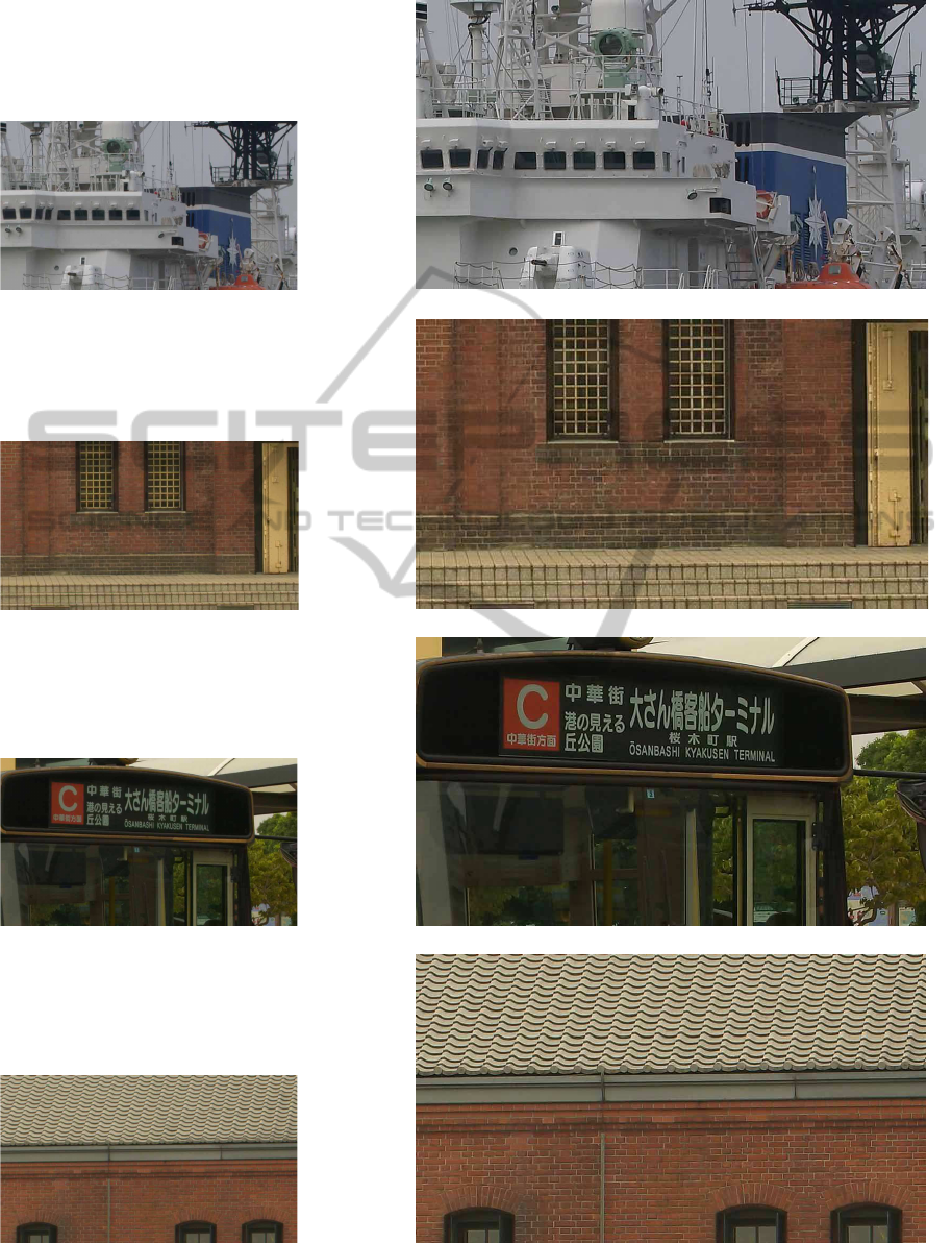
(a) 4K ship (b) 8K ship
(c) 4K wall (d) 8K wall
(e) 4K bus (f) 8K bus
(g) 4K roof (h) 8K roof
Figure 13: 4K and up-converted 8K images.
Real-timeSuperResolutionEquipmentfor8KVideo
155

NLSP in real time. The images enlarged with NLSP
do not show any blur. This means NLSP improves
resolution. The up-converter also works in real time
(60 Hz).
7 CONCLUSIONS
NLSP real-time hardware for 8K was presented.
Since the NLSP algorithm can create high-frequency
elements that the original image does not have, it can
create a high-resolution image in spite of the enlarge-
ment. Using parallel signal processing and a 2D-LPF,
it works in real time even on enlarged 8K video shown
at 60 Hz. The use of NLSP in up-conversion from 4K
to 8K removes the blur caused by the enlargement and
works in real time. It also has a focusing effect and
can be applied to defocused video in real time. The
papers on Super Resolution Image Reconstruction re-
ported the PSNR between the original image and SR
processed images since those studies used the origi-
nal images. However, there are no original 8K images
used in the examples of this paper. The subjective as-
sessment is the only assessment method, and it will
remain as future work to examine the possibility of
developing a more objective measure.
REFERENCES
W. F. Schreiber, ”Wirephoto Quality Improvement by Un-
sharp Masking”, J. Pattern Recognition, 2, 1970, pp.
111-121.
J-S. Lee, ”Digital Image Enhancement and Noise Filter-
ing by Use of Local Statistics”, IEEE Trans. Pattern
Analysis and Machine Intelligence, PAMI-2, 2, March
1980, pp. 165-168.
W. K. Pratt, ”Digital Image Processing (3rd Ed)”, John
Wiley and Sons, 2001, pg. 278.
S. C. Park et al., ”Super-Resolution Image Reconstruc-
tion: A Technical Overview”, IEEE Signal Processing
Magazine, 1053-5888/03, pp. 21-36, May, 2003.
S. Farsiu et al., ”Fast and Robust Multi-frame Super-
resolution”, IEEE Transactions on Image Processing
, vol. 13, no. 10, pp. 1327-1344, October, 2004.
A. W. M. van Eekeren et al., ”Multiframe Super-
Resolution Reconstruction of Small Moving Objects”,
IEEE Transactions on Image Processing, pp. 2901-
2912, Vol. 19, No. 11, November, 2010.
Xianghua Houa et al., ”Super-resolution Image Recon-
struction for Video Sequence”, 2011 International
Conference on Electronic & Mechanical Engineering
and Information Technology, pp. 4600-4603, 12-14
August, 2011.
Matan Protter et al., ”Generalizing the Nonlocal-Means
to Super-Resolution Reconstruction”, IEEE Transac-
tions on Image Processing, pp. 36-51, Vol. 18, No. 1,
Jan. 2009.
S. Panda et al., ”POCS Based Super-Resolution Image
Reconstruction Using an Adaptive Regularization Pa-
rameter”, IJCSI International Journal of Computer
Science Issues, Vol. 8, Issue 5, No. 2, September 2011,
ISSN (Online), 1694-0814.
P. Mertz and F. Gray, ”A Theory of Scanning and Its Rela-
tion to the Characteristics of the Transmitted Signal in
Telephotography and Television”, Bell System Tech-
nical Journal, Vol.63B, pp.464-515, (1934).
S. Gohshi and I. Echizen, ”Limitations of Super Resolution
Image Reconstruction and How to Overcome them for
a Single Image”, ICETE2013 (SIGMAP), Reykjavik,
Iceland , pp. 71-78, July, 2013.
N. Matsumoto and T. Ida, ”Reconstruction Based Super-
Resolution Using Self-Congruency around Image
Edges”, Journal of IEICE , Vol. J93-D, No. 2, pp. 118-
126, Feb. 2010 (in Japanese).
Seiichi Gohshi et al., ”Real-Time Up-Converter from HDTV
to 4K with Super Resolution”, 42.2, pp. 582-585,
0097-966X-13-4402, Society for Information Display
SID 2013 DIGEST, 23rd May 2013.
H. Sakata, ”Assessment of TV noise and Frequency Charac-
teristics”, Journal of ITE , Vol. 34, No. 3, pp. 239-245,
Mar. 1980 (in Japanese).
Seiichi Gohshi, ”Limitation of Super Resolution Image Re-
construction for Video”, Computational Intelligence,
Communication and Networks (CICSyN), Madrid,
Jun. 2007.
M. A. T. Figueiredo and R. D. Nowak, ”An EM algorithm
for wavelet-based image restoration”, IEEE Transac-
tions on Image Processing, vol. 12, pp. 906-916, Aug.
2003.
Hanjie Pan , Thierry Blu, ”Sparse Image Restoration us-
ing Iterated Linear Expansion of Thresholds”, Image
Processing (ICIP), pp. 1905 - 1908, 18th IEEE Inter-
national Conference, Sept. 2011.
Stephen Karungaru, Masakazu Sugizaki, Minoru Fukumi,
Yasue Mitsukura, and Norio Akamatsu, ”Out-of-
Focus Blur Image Restoration using the Akamatsu
Transform”, Industrial Electronics, IECON ’09. 35th
Annual Conference of IEEE, pp. 4257-4261, Nov.
2009.
SIGMAP2014-InternationalConferenceonSignalProcessingandMultimediaApplications
156
