
Transforming Viewpoints of Distributed Designs to Support Simulation
Scenarios
Iyas Alloush
1,2
, Yvon Kermarrec
1,2
and Siegfried Rouvrais
1,3
1
Telecom Bretagne, Institut Mines-Telecom, Universit
´
e europ
´
eenne de Bretagne, Bretagne, France
2
UMR CNRS 6285 Lab-STICC, Bretagne, France
3
IRISA, Campus Universitaire de Beaulieu, Rennes, France
Keywords:
Enterprise Architecture, Viewpoint, Model Driven Engineering, Code Generation, Network Simulation, IMS.
Abstract:
In order to reduce the time to market and improve the qualities during the service construction activities, we
provide the designers with integrated tools that help them to construct services. They are able to evaluate their
designs earlier according to functional, performance non-functional, and QoS requirements. The contribution
of this paper is concerned with representing the different viewpoints of a design model in the simulation
scenario through code generation. The main benefits of our approach based on separation of concerns are to
better manage the complexity of the design and to improve the fine-tuning level of simulation scenarios. We
illustrate our approach with a video conference service relying on the IP Multimedia Subsystem platform.
1 INTRODUCTION
In the context of Service Creation Environments
(SCE)s (Adamopoulos et al., 2002), the TS design
is a major activity where any mistake results in ma-
jor consequences in later phases. It may lead to in-
stallation/deployment of the hardware elements in the
wrong way. The Telecom Service (TS) designs con-
tain process behaviors and structural elements that
represent the underlying networks on which they will
operate. Thus, the TS design is complex due to the di-
versity of different domains and perspectives that are
used. This results in increasing the time of the design
phase and the errors that can be made by TS design-
ers.
In order to improve the time to market and cost
factors, we are interested in the evaluation of the TS
design earlier than the implementation phase accord-
ing to the functional, performance non-functional,
and QoS requirements. We consider reduction of
complexity and facilitation of error detection in the
TS design to be important add-ons in the tools that we
aim to provide, where they form the main motivation
behind the contribution of this paper.
Network simulation makes it possible to obtain
valuable measures/traces from the TS design and de-
tect errors or quality flaws by early analysis of these
results. The contribution in this paper is connected di-
rectly to the network simulation scenarios. It is a con-
tinuation to our recent results in (Alloush et al., 2013).
In this former proposal we have proposed an approach
to bridge the language gap between modeling and net-
work simulation activities relying on model transfor-
mations and the Enterprise Architecture (EA) stan-
dard (Noran, 2003; Quartel et al., 2009). This is
achieved by generating simulation scenarios that can
be run directly by classical simulators: e.g. OPNET,
NS-3. The modeling language (ArchiMate) relies on
the EA standard, thus it has an architecture that shares
the different viewpoints
1
in the design thanks to the
multiple layers that it has (business, application, tech-
nology).
Representing these highly abstract layers in the
simulation program helps, at least, to check the data
flow between the design elements (from cause to the
result). Based on that context and problematic, the
research question is: How to transform the multiple
viewpoints of ArchiMate from the TS highly abstract
design to the scenario of classical network simula-
tors?.
In this paper we present our contribution in con-
veying the viewpoints represented in ArchiMate/EA
to the simulation scenario. We rely on our code gen-
1
According to the IEEE 1471-2000: A viewpoint is con-
sidered as the central concept for organizing software archi-
tectures. Its main goal is to facilitate the comprehension of
complex systems by providing separation of concerns.
321
Alloush I., Kermarrec Y. and Rouvrais S..
Transforming Viewpoints of Distributed Designs to Support Simulation Scenarios.
DOI: 10.5220/0004997103210328
In Proceedings of the 9th International Conference on Software Engineering and Applications (ICSOFT-EA-2014), pages 321-328
ISBN: 978-989-758-036-9
Copyright
c
2014 SCITEPRESS (Science and Technology Publications, Lda.)

erator presented in (Alloush et al., 2013) where we
select NS-3 as a target tool.
As benefits and in addition to the rapid and au-
tomated code generation of the simulation program
(Alloush et al., 2013), our contribution helps the TS
designer during the evaluation of the design model
by: (1) improving the clarity of the generated code
as it applies some object oriented ”class concept”; (2)
improving the reconfigurability of the simulation pa-
rameters and service functions as they are abstracted;
(3) separating the control from the user plane descrip-
tions thanks to the separation between the application
and technology layers in the design model.
This paper is structured as follows: In section 2,
we present the related work by analyzing the similar-
ities and differences from our work. Section 3 high-
lights the service creation environments and points to
our approach. In section 4, we explain the EA and
ArchiMate concepts that directly affect our contribu-
tion. In section 5, we present the main concept of
code generation in the picture of the Model Driven
Engineering (MDE) discipline. We present our map-
ping method (contribution) to transform the multiple
viewpoints of ArchiMate to the scenarios of network
simulation. In section 6, we illustrate our approach by
an example from the TS domain: a Video Conference
service and we analyze the results. Finally, section 7
contains the conclusion and the future work.
2 RELATED WORK
Design architecture and composition, tool capabilities
and domains, are important points to be considered as
they are related to the transformation of the design
architecture (design tool) to the simulation program
(evaluation tool). We are interested in the following
concerns: (C1) the verification tool capabilities that
are used in the evaluation process and their domain,
as the code generation process follows the target ver-
ification tool in our approach; (C2) the consideration
of the behavioral and structural aspects in the design
model. This concern is related to the modeling lan-
guage (see section 4); (C3) the consideration of the
different viewpoints inside the design model. This
concern is related to the modeling language too (see
section 4). There are different approaches and SCEs
that help to make early verification before the imple-
mentation phase. In the following, we present some
of them and we analyze according to the stated con-
cerns.
MDE helps to manage complexity thanks to the
modeling and model transformation fundamentals.
All of the following related works rely on the MDE
discipline.
• The usage of the verification tools (C1) is guided
by their capabilities to produce measures that
help to evaluate the design. Some of these tools
are specific to an analytic domain like perfor-
mance analysis. Cheddar
2
simulator (Dissaux
and Singhoff, 2008) is an example of such a
domain specific tool, it can help the designer
to make performance analysis such as feasibil-
ity tests through real-time scheduling simulation.
Verification tools can differ according to their
type of analysis, such as model checkers. In
(Berthomieu et al., 2010), the authors rely on
the FIACRE pivot language and Tina tool-chain
to make behavioral verifications depending on
Timed Transition Systems (TTS). The difference
from our work is that we rely on classical tools (or
COTS
3
): NS-3 and OPNET. Additionally, these
tools cover a wide range of domains and ap-
plications (e.g. WIFI, LTE, etc), and different
traces/logs too. These tools (network simulators)
can make behavioral and performance verifica-
tions in the networking domain at the same time;
• Regarding the design aspects (C2), they are
mainly divided into behavioral and structural con-
cepts. The behavioral aspects correspond to the
functional description of the system. The struc-
tural ones are used to identify the place where the
behavior(s) should be executed. In the TS cre-
ation domain, value-added services are designed
relying on the APIs that are provided by the un-
derlying platform as in IP Multimedia Platform
(IMS) in (Shin et al., 2008), SIP transactions to
control services as in (Hartman et al., 2007), or
Open Service Architectures (OSA) and Parlay in
(Bakker and Jain, 2002; Glitho et al., 2003). How-
ever, all of these approaches do not consider the
performance evaluation of the hardware elements
in the system design, where they concentrate on
implementing the functions and protocols only. In
our approach, we consider both the behavioral and
structural (including hardware elements) aspects
thanks to the concepts of the modeling language
(ArchiMate).
• Regarding the multiple viewpoints (C3) concern,
the authors in (Berthomieu et al., 2010) rely on
the AADL language to model their design. AADL
enables the designer to separate software compo-
nents of the system (e.g. process, thread, etc) from
2
Cheddar framework: http://beru.univ-brest.fr/∼singhoff/
cheddar/#Ref6
3
COTS is a synonym for ”Commercial Off-The-Shelf”
existing tools.
ICSOFT-EA2014-9thInternationalConferenceonSoftwareEngineeringandApplications
322

the components of the execution platform (e.g.
processor, bus, memory, device, etc). This manner
of describing the system is close to our approach
thanks to the separation between the design as-
pects in AADL, but the difference is that their ap-
proach is proper for real-time systems (RTS) and
that AADL does not provide business modeling
capability as in ArchiMate.
In (Shin et al., 2008; Yelmo et al., 2008), the au-
thors propose SCEs in the domain of value-added
services (TSs). Both of the approaches consider
one viewpoint during the design phase: the end-
user as a designer to involve him in the service
creation activities. Furthermore, in both of (Agar-
wal et al., 2005; Achilleos et al., 2010), the au-
thors consider the service designer who is not the
benefiter of the service. These approaches do not
consider multiple viewpoints in the design phase
of a TS. The difference is that our approach relies
on the IMS platform specifications as represented
in the technology layer of ArchiMate. Therefore,
the difference is in the underlying technology rep-
resentations and the nature of the descriptions of
the elements in the application layer. ArchiMate
provides a proper abstraction in all layers, and
makes it possible to extend its concepts accord-
ing to the needs of different domains (to produce
DSMLs) under the ceiling of the IT domain.
3 SERVICE CREATION
ENVIRONMENTS
Service creation environments (SCE)s rely on soft-
ware tools that are used to achieve the service de-
velopment methodology. The aim of the SCEs is to
assist the service developers by automating and sim-
plifying the service creation process. In our approach
Requirements
refinement
Artifacts
synchronization
Service analysis
Service design
Service
implementation
Early verification
Service validation
and testing
Define:
•use cases
•user interfaces
•service interaction
diagrams
•service design class
diagram
•service architecture layers
Satisfies
Requirements?
no
yes
•Syntax checking (code generator)
Auto-generate:{
• simulation scenarios
•Configuration of measures/traces
•analysis based on analytic theories
}
modify
Design
modeling
language
uses
Figure 1: Extending the design activities by early verifica-
tion in the service development framework, inspired from
(Adamopoulos et al., 2002).
(Fig. 1), we contribute by extending the design phase
to include our proposed early verification activity (Al-
loush et al., 2013). In order to assist the service de-
signer, we generate tools (Chiprianov et al., 2011) that
help to avoid syntax errors and errors in the relation-
ships between the elements of the design. Addition-
ally, we generate simulation scenarios automatically
to be run directly in network simulators: OPNET and
NS-3 (Alloush et al., 2013).
4 ENTERPRISE ARCHITECTURE
AND ARCHIMATE
In this section, we present the EA and ArchiMate
modeling language, as our contribution relies directly
on ArchiMate concepts.
According to (Jonkers et al., 2006), the enterprise
architecture (EA) is defined as: ”a coherent whole
of principles, methods, and models that are used
in the design and realization of the enterprise’s or-
ganizational structure, business processes, informa-
tion systems, and infrastructure”. The EA objective
is to define frameworks that provide a way to struc-
ture concepts and activities necessary for designing
and building systems. The Open Group Architecture
Framework (TOGAF) covers the activities that are re-
lated to the IT domain. The closest EA modeling lan-
guage to TOGAF is ArchiMate. This makes Archi-
Mate suitable for modeling telecommunication appli-
cations and development.
ArchiMate includes the three phases of TOGAF
(Fig. 2): Business Architecture, Information Sys-
tems Architecture, and Technology Architecture. It
represents these architectures using three correspond-
ing layers. Furthermore, it can provide interoperabil-
ity between these three layers thanks to the different
dependencies and the passive structural elements that
ArchiMate contains.
Like other modeling languages ArchiMate has
both (abstract and concrete) syntaxes and semantics.
The multi-layered architecture is represented in the
meta-model of ArchiMate that represents the abstract
syntax of the modeling language. Every layer con-
tains different concepts: structural, behavioral, and
passive structural (C2 in section 2). This helps the de-
signer of the service to represent the system from dif-
ferent viewpoints (multi-layers) (C3 in section 2), and
provides the ability to represent software and hard-
ware concepts (behavioral and structural aspects).
Regarding the business layer, it contains the concepts
that can describe any business process through mod-
eling (e.g. business actor, business function, process,
etc). Our approach considers that the concepts of this
layer are proper to the usage of the end-user in the TS
TransformingViewpointsofDistributedDesignstoSupportSimulationScenarios
323
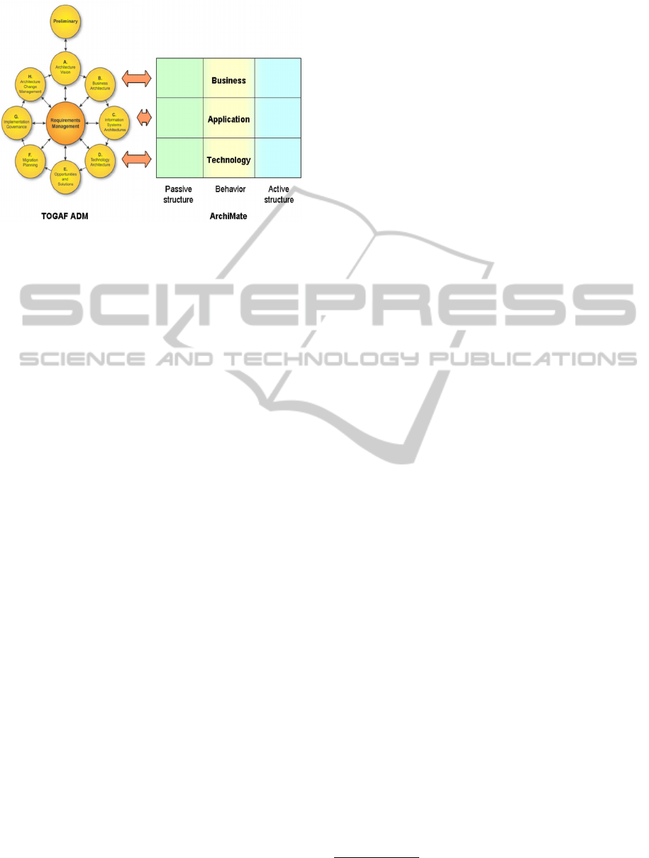
Figure 2: The correspondence between TOGAF and Archi-
Mate (Chiprianov, 2012).
domain. With regard to the application layer, it rep-
resents the service applications and the different sys-
tems (e.g. video conferencing system, push-to-talk
system etc) and how they interact with each other. It
contains several important elements (e.g. application
components, application interfaces, functions, etc).
Finally, the technology layer represents the underly-
ing platform that is able to run/execute the applica-
tions of the service. We have contributed to this layer
by extending it to include IMS core-network concepts
(Chiprianov et al., 2011) through a domain specific
modeling language (DSML).
Including of IMS concepts and constraints in
ArchiMate gives the designer the ability to benefit
from the different functions of IMS. The other advan-
tage is that these new concepts provide us with syntax
that enables us to generate network simulation scenar-
ios directly from the design models, for OPNET and
for NS-3.
5 EXPRESSING THE
VIEWPOINTS OF ARCHIMATE
IN THE NETWORK
SIMULATION SCRIPTS
In this section, we present our method to transform
the multi-layered architecture of the ArchiMate mod-
eling language (see section 4) to the NS-3 simulation
scenario through the code generation process.
The objective from the viewpoints concept is to
organize the different activities between the designers
from different domains and backgrounds. The point
of transforming this concept to the network simula-
tion is to represent the different actors, roles, func-
tions, components in order to: (1) trace the flow of
execution of the design; (2) implement functions even
if abstracted for override (reconfiguration) later by the
developers according to their needs; (3) separate the
concepts of the TS design (user and control planes)
in the simulation program. On one hand, ArchiMate
provides a language to describe the EA through its
multiple layers and the different domains of concepts.
On the other hand, NS-3 (Henderson et al., 2006) re-
lies on class concepts as it accepts the C++ language
for configuration. The C++ program can control the
simulation scenario through different APIs that are
provided by the libraries of the NS-3 simulator. Our
method in this section relies on these features of both
the ArchiMate language and the NS-3 simulator to ex-
press the architecture of ArchiMate in the simulation
C++ program.
The Eclipse IDE
4
is a powerful IDE rich in plug-
ins and tools to start with research and development.
The Eclipse modeling framework (EMF)
5
provides us
with a powerful means to model and generate codes in
the Model Driven Engineering discipline. There are
many languages that are used for model transforma-
tions (e.g. ATL as a model-to-model transformation,
and XPAND as a model-to-text transformation). We
chose the XPAND language to build templates that
are used to generate simulation code directly from
design models relying on the abstract syntax of the
modeling language. XPAND is used because it con-
tains means to make syntax checks, and to analyze
and manage the replacement of variables with their
values from the design model. This replacement oc-
curs side by side with the static implementations that
respects the language of the target tool.
In the following we present the mapping rules that
we implement through the XPAND model transfor-
mation: (1) Every Business Actor or Role, and Appli-
cation Component in the design model is mapped as
a class in NS-3; (2) Every Business Function or Ac-
tivity, and Application Function in the design model
is mapped as a function that is implemented in the
corresponding class in NS-3 (correspondence is rep-
resented by an assignment relationship in the de-
sign model); (3) The relationship between the func-
tions/activities of the different layers is accepted to
be an association relationship while it is excluded
(through the model transformation analysis) when it
occurs between elements that do not belong to two
consequent layers; (4) The calls between the func-
tions in the simulation scenario are initiated by trig-
gering and cross-layer association relationships in the
design model; (5) Regarding the technology layer
mapping, it stays as implemented in (Alloush et al.,
2013); (6) The initialization behavior that starts the
4
Eclipse IDE website: https://www.eclipse.org
5
EMF website: https://www.eclipse.org/modeling/emf/
ICSOFT-EA2014-9thInternationalConferenceonSoftwareEngineeringandApplications
324

sequence of function calls in NS-3 is by default the
starting function of the business layer.
We implement these rules using XPAND lan-
guage. The first function that initiates the call se-
quence is the start function and should be in the busi-
ness layer. The instantiation of its class (assigned
business actor) and the function call are done in the
main function of the simulation program (C++ pro-
gram). In order to implement all of the classes in the
same simulation program (one file), we start by im-
plementing the application layer elements then we go
up to the business ones. This is because the applica-
tion classes are to be instantiated in the business ones
and so they should be declared beforehand. Figure.
3 presents an algorithm to list the application com-
ponents of the application layer (in ArchiMate) in re-
verse order from that of the function calls. The same
algorithm is used to order the elements of the business
layer.
After having listed the model elements in the
proper order for the simulation program, we iterate
over the elements of these lists (application then busi-
ness layers) to create an application class in NS-3
6
for
each element. The assignment relationship helps to
establish the correspondence between functions and
structural elements (in Fig. 4, the assignment rela-
tionship is shown between ’Conference System’ and
the function ’response checking’). This helps the code
generator to correctly implement the functions in the
corresponding application class of the simulation pro-
gram.
With regard to the calls between the different
functions (Fig. 6), there are two cases according to
the triggering relationship (intra-layer callings): (1)
the source and target functions belong to the same
class/component - then there is no need to instanti-
ate a class (call is direct); (2) the source and target
functions belong to different classes/components - in
this case there is a need to instantiate the target class
in the source one. Another case is considered: the
association relationship between two functions that
belong to different layers (inter-layer calls). In this
case, we instantiate the class of the target function and
then call the destination function (except for the case
when the target belongs to the technology layer where
we call the function directly because all of the tech-
nology functions are declared at the beginning of the
simulation program).
The intra and inter layer calls contribute to the
concern (C3) in section 2 through achieving the in-
6
In NS-3, an application class is a class that has start
and stop application functions for overriding purpose. One
to many application classes can be assigned to the node of
NS-3.
teroperability between the different layers and repre-
senting that in the simulation program. Mapping the
design aspects (behavioral, structural) using the appli-
cation class concept helps to improve the fine-grained
level of the simulation program - this contribution is
related to the concern (C2) in section 2. Additionally,
relying on NS-3 enables us to verify and test designs
of different distributed systems (different applications
and objectives) according to the networking domain
and performance non-functional requirements - this
contributes to the concern (C1) in section 2.
6 VIDEO CONFERENCE
EXAMPLE
In order to illustrate our approach on transforming the
different viewpoints (concepts from different layers)
of the ArchiMate language to the scenario of the net-
work simulator (NS-3 v3.13), we present an example
of a TS - video conference - (VCTS).
6.1 Design Models
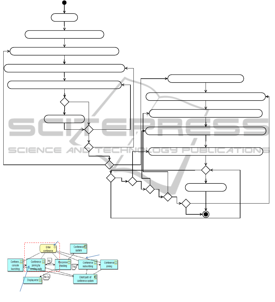
The VCTS design model is divided into 3 views: busi-
ness, application, and technology. In our approach,
we consider that the business layer model includes the
end-user activities represented in business processes
which is a high abstract level process. Furthermore,
we consider the application layer view as represent-
ing the system components (Fig. 4), in this case study
it is video conferencing system (Chiprianov, 2012;
Chiprianov et al., 2011). Application-layer system
functions call technology-layer functions thanks to
the association relationship that is defined in Archi-
Mate standards. The sequence of the technology func-
tions is designed according to the video conference
sequence diagram that is mentioned in (Camarillo
and Garc
´
ıa-Mart
´
ın, 2008). This diagram represents
the message flow and the domain-specific activities
that are related to the IMS core-network. The design
tool in (Chiprianov, 2012) insures the conformance
between the specifications of the modeling language
(DSML) and the design model instance created by the
service designer.
6.2 Observations and Analysis
Our contribution in this paper is to represent the dif-
ferent viewpoints of the design (distributed system)
in the simulation scenario. In order to insure that this
representation is accurate, it is important to insure:
(1) the correct transformation of the flow of execu-
tion to the simulation program (call continuity from
TransformingViewpointsofDistributedDesignstoSupportSimulationScenarios
325
Start
Collect the ApplicationComponents; List AC; iterator i
Collect AssignmentRelations: where source.id = AC.id; List Asign; iterator j
Collect TriggeringRelations: where source.id = Asign.target.id; List trig1; iterator k
Collect TriggeringRelations as list: where source.id = trig1.target.id; List trig2
trig2.isEmpty?
Add AC to list AC_ordered
Yes
k!=0
No
No
j!=0
Yes
i!=0
Yes
No
No
Yes
Collect ApplicationComponents; List AC1; iterator ii
Collect ApplicationComponents: where id = AC_ordered.last.id; List ACT; iterator jj
Collect AssignmentRelations: where source.id=ACT.id; List Asign2; iterator kk
Collect TriggeringRelations: where target.id=Asign2.target.id; List trig2; iterator LL
Collect AssignmentRelations: where target.id=trig2.source.id; List A; iterator F
if !(A.source.id=ACT.id && AC_ordered.collect(where id=A.source.id).isEmpty)
AC_ordered.add(A.source)
Yes
F!=0
LL!=0
No
kk!=0
No
jj!=0
No
ii!=0
No
End
AC_ordered={}
No
No
Yes
Yes
Yes
Yes
Yes
Figure 3: Reverse ordering of structural elements in Application Layer/ArchiMate.
Our scope for
simulation
Business Activity (end-user viewpoint)
Association Relationship
Application Function to initiate the message flow
(signaling in the technology layer), System viewpoint
Figure 4: Application layer view from the design model of
the video conference TS using DSML (Chiprianov, 2012).
cause/event triggered by the business actor to the ex-
ecution in the node); (2) the correct implementation
according to the target tool language (C++).
NS-3 compiles the simulation code according to
the C++ language and to the constraints of the net-
working domain. Executing the the command (./waf
–run scratch/scenario-name) leads to compilation of
the simulation scenario and then execution of the net-
work simulation. The compilation and network sim-
ulation (through NS-3) show no errors or warnings.
All of the trace and capturing (.pcap) files were gen-
erated too. This means that the classes and functions
are all declared in the right order thanks to the algo-
rithm in (Fig. 3), and that both the class instantiation
and function calls are correct according to the C++
language rules.
Figure 6 shows the correspondence between the
different layers of the design and the generated code
for NS-3. One notices that calls between functions
in the C++ code can be intra- or inter- layer. This
insures the continuity of calls between the different
functions in the same layer and the interoperability
between the consecutive layers. Thus, causality of be-
havior (flow of execution) is guarantied to be correctly
transformed (when) using our approach. In the same
figure, it is clear that the application configuration is
realized in the functions and classes of the applica-
ICSOFT-EA2014-9thInternationalConferenceonSoftwareEngineeringandApplications
326

Figure 5: Snapshot of the NetAnim animator
EnterConference
Set
Parameters
Start
CreateInvite
Other functions
association
association
triggering
triggering
Business layer
Application layer
void Clientpartiofconferencesystem::APF_ApplicationFunction_SetParameters_6c8b38c (void){
Clientpartiofconferencesystem::APF_ApplicationFunction_JoinConference_6b8b38b();
}
void Clientpartiofconferencesystem::APF_ApplicationFunction_JoinConference_6b8b38b (void){
Clientpartiofconferencesystem::APF_ApplicationFunction_WaitForResponsesFromNetwork_6c8b38d();
TF_CreateInvite_START_f9f8e9b1();
}
void CustomerUser::StartApplication
(void){CustomerUser::Bus_BusinessFunction_Enterconference_981ed8e7();}
…
void CustomerUser::Bus_BusinessFunction_Enterconference_981ed8e7
(void){CustomerUser::Bus_BusinessFunction_Start_Stop_ca0cf0e8();
Clientpartiofconferencesystem::APF_ApplicationFunction_SetParameters_6c8b38c();}
void CustomerUser::Bus_BusinessFunction_Start_Stop_ca0cf0e8
(void){CustomerUser::Bus_BusinessFunction_Chat_d302c74d();}
Technology layer
JoinConference
//#1
void TF_CreateInvite_START_f9f8e9b1 (){
cout<<"Function START_f9f8e9b1 in Node Terminal 1 is running at "<< Simulator::Now ()<<endl;
//Enternal function, Current node: Terminal 1, Current node id: 964b5e8e, Current function: f9f8e9b1
TF_CreateInvite_CreateInvite_f9f8e9b2();
}
//#2
void TF_CreateInvite_CreateInvite_f9f8e9b2 (){
cout<<"Function Create Invite_f9f8e9b2 in Node Terminal 1 is running at "<< Simulator::Now ()<<endl;
//Enternal function, Current node: Terminal 1, Current node id: 964b5e8e, Current function: f9f8e9b2
TF_SendTo_Sendto_41533d58("OK");
}
NS-3 Code
Figure 6: Interoperability between the EA-layers in the
Simulation Scenario
tion layer where the signaling actions (e.g. exchang-
ing SIP messages) and hardware internal functions of
IMS are represented in the technology layer elements.
This confirms the ability to separate the control- and
user- planes in both the design and simulation tools.
In order to check the correspondence of the mes-
sage flow with the design, we used the NetAnim tool
that reads the auto-generated animation scenario file
and displays the packet flow (Fig. 5). Additionally,
we have used wireshark
7
in order to analyze the sig-
naling traffic and check its correspondence with the
design model.
7 CONCLUSIONS AND FUTURE
WORK
In this paper, we have presented our contribution to
transforming the viewpoints of Enterprise Architec-
ture standard from a design model of a telecom ser-
vice (as a case study of a distributed system) to the
network simulation technical space (NS-3 simulator).
We have proposed model transformation rules that
insure the transparent mapping between the design
model and the simulation technical spaces.
Our approach reduces the time of the verification
7
Wireshark network-traffic analyzer:
http://www.wireshark.org/
during the design phase earlier before the implemen-
tation or deployment ones. This corresponds to the
automated actions in the model transformation. Ac-
cording to our approach in extending design activities,
we are now able to provide a tool chain (Mellor, 2002)
that integrates support for development tools useful
for the SCEs (Adamopoulos, 2009). These tools are
extensible as they can be generated from meta-models
(e.g. Archi tool) and they rely on the Eclipse Model-
ing Framework that is well supported and widely used
too. Additionally, as far as we know, there is not yet
any state of the art code generation technique to link
between models and classical (or COTS) tools like
NS-3 simulator. We make use of the architecture of
ArchiMate to generate a fine-grained simulation pro-
gram. This enables the designer to reconfigure the
part of the code that is related to his domain experi-
ence. Our model transformation enables the designer
to generate complex and large simulation scenarios
directly from the design model in a very short time
(few seconds). Additionally, it helps to separate the
user and control planes in the simulation program. On
the other hand, the implementation of the transforma-
tion template consumes considerable time and needs
accuracy and domain experience in both the modeling
and network simulation activities.
In the future, we expect to generate executable
analysis scripts from the constraints that belong to
the performance and QoS requirements. These scripts
can be run directly in COTS such as MATLAB. Anal-
ysis tools helps to obtain valuable feedbacks that help
the designer to make decisions to improve the design
quality. Additionally, we intend to provide a checker
for the domain-specific constraints that are related to
the language (DSML) through the code generation
process. This checker should generate reports that
help the designer to modify the model efficiently.
REFERENCES
Achilleos, A., Yang, K., and Georgalas, N. (2010). Context
modelling and a context-aware framework for perva-
sive service creation: A model-driven approach. Per-
vasive and Mobile Computing, 6(2):281 – 296.
Adamopoulos, D. (2009). A service-centric approach for
exploiting network intelligence. In Second Interna-
tional Conference on the Applications of Digital Infor-
mation and Web Technologies, 2009. ICADIWT ’09.,
pages 145 –150.
Adamopoulos, D., Pavlou, G., and Papandreou, C. (2002).
Advanced service creation using distributed ob-
ject technology. Communications Magazine, IEEE,
40(3):146 –154.
Agarwal, V., Dasgupta, K., Karnik, N., Kumar, A., Kundu,
A., Mittal, S., and Srivastava, B. (2005). A service
TransformingViewpointsofDistributedDesignstoSupportSimulationScenarios
327

creation environment based on end to end composi-
tion of web services. In Proceedings of the 14th Inter-
national Conference on World Wide Web, WWW ’05,
pages 128–137, New York, NY, USA. ACM.
Alloush, I., Kermarrec, Y., and Rouvrais, S. (2013). A gen-
eralized model transformation approach to link design
models to network simulators: NS-3 case study. In In-
ternational Conference on Simulation and Modeling
Methodologies, Technologies and Applications (SI-
MULTECH 2013), pages 337–344. SciTePress Digital
Library.
Bakker, J.-L. and Jain, R. (2002). Next generation service
creation using xml scripting languages. In Communi-
cations, 2002. ICC 2002. IEEE International Confer-
ence on, volume 4, pages 2001–2007.
Berthomieu, B., Bodeveix, J.-P., Zilio, S. D., P.Dissaux,
Filali, M., Gaufillet, P., Heim, S., and Vernadat, F.
(2010). Formal verification of AADL models with FI-
ACRE and TINA. In Embedded Real Time Software
and Systems (ERTS) 2010.
Camarillo, G. and Garc
´
ıa-Mart
´
ın, M. A. (2008). ”The 3G
IP Multimedia Subsystem (IMS) Merging the Internet
and the Cellular Worlds”. John Wiley and Sons, Ltd,
third edition.
Chiprianov, V. (2012). Collaborative Construction of
Telecommunications Services. An Enterprise Archi-
tecture and Model Driven Engineering Method. PhD
thesis, Telecom Bretagne, France.
Chiprianov, V., Alloush, I., Kermarrec, Y., and Rouvrais,
S. (2011). Telecommunications service creation: To-
wards extensions for enterprise architecture model-
ing languages. In 6th Intl. Conf. on Software and
Data Technologies (ICSOFT), volume 1, pages 23–29,
Seville, Spain.
Dissaux, P. and Singhoff, F. (2008). Stood and cheddar:
Aadl as a pivot language for analysing performances
of real time architectures. In Proceedings of the Euro-
pean Real Time System conference, Toulouse, France.
Glitho, R., Khendek, F., and De Marco, A. (2003). Cre-
ating value added services in internet telephony: an
overview and a case study on a high-level service cre-
ation environment. volume 33, pages 446–457.
Hartman, A., Keren, M., Kremer-Davidson, S., and Pikus,
D. (2007). Model-based design and generation of tele-
com services.
Henderson, T. R., Roy, S., Floyd, S., and Riley, G. F. (2006).
ns-3 project goals. In Proceeding from the 2006 work-
shop on ns-2: the IP network simulator, WNS2 ’06,
New York, USA. ACM.
Jonkers, H., Lankhorst, M., ter Doest, H., Arbab, F., Bosma,
H., and Wieringa, R. (2006). Enterprise architecture:
Management tool and blueprint for the organisation.
Information Systems Frontiers, 8(2):63–66.
Mellor, S. J. (2002). Make models be assets. Commun.
ACM, 45(11):76–78.
Noran, O. (2003). An analysis of the zachman framework
for enterprise architecture from the GERAM perspec-
tive. Annual Reviews in Control, 27(2):163 – 183.
Quartel, D., Engelsmanb, W., Jonkersb, H., and van Sin-
derenc, M. (2009). A goal-oriented requirements
modelling language for enterprise architecture. In
Enterprise Distributed Object Computing Conference,
2009. EDOC ’09. IEEE, pages 3 – 13. University of
Twente.
Shin, Y., Yu, C., Chung, S., and Kim, S. (2008). End-user
driven service creation for converged service of tele-
com and internet. In AICT ’08. Fourth Advanced Inter-
national Conference on Telecommunications, pages
71–76.
Yelmo, J., del Alamo, J., Trapero, R., Falcarm, P., Yi,
J., Cairo, B., and Baladron’, C. (2008). A user-
centric service creation approach for next generation
networks. In Innovations in NGN: Future Network
and Services, 2008. K-INGN 2008. First ITU-T Kalei-
doscope Academic Conference, pages 211–218.
ICSOFT-EA2014-9thInternationalConferenceonSoftwareEngineeringandApplications
328
