
Evaluation of Femtocell Technology Challenges and Its Power
Control Methodologies for Green Heterogeneous Networks
Mazen Al Haddad and Magdy Bayoumi
Center for Advanced Computer Studies, University of Louisiana at Lafayette, Lafayette, LA, U.S.A.
Keywords: Small Cells, Femtocell Technology, LTE, Hetnet.
Abstract: Femtocell technology brings extended low-power radio coverage directly in the indoor premises, where
propagation loss is typically highest. It also enriches both macrocell wide-area and in-building solutions in
terms of coverage & capacity. The integration of femtocells into heterogeneous cellular networks is foreseen
as a low-power and low-cost solution to cope with the exponential growth of required data traffic volumes,
offload the macro base stations and offer high performance mobile networks. However, the massive and
unplanned deployment of femtocells and their uncoordinated operations may result in harmful co-channel
interference and cause significant power waste in order to maintain an acceptable user performance. In this
work, we survey the technical challenges of femtocells deployment and the available energy control
techniques. Moreover, we look into adaptive mechanisms for femtocell technology to cover the way
towards green-oriented mobile networks. Our intention is to examine how femtocell deployment can share
the available radio resources efficiently in order to limit the average power consumption and mitigate co-
channel interference. Besides the introduction of the basic ideas for optimizing the spectral and energy
efficiency in femtocell networks, typical interference management techniques are discussed too, with a
special emphasis on power control methodologies.
1 INTRODUCTION
Recent analysis has shown that wireless networks,
not data centers, are the biggest energy drain in
cloud services. This is because more and more
people are accessing wireless networks with the
prospect of being connected anywhere and anytime.
Tablets, smartphones and laptops no longer need to
connect to wireless networks via cable. Instead,
WiFi or indoor/outdoor cellular solutions which are
inherently energy inefficient and a heavy contributor
to energy consumption are used (Bell Labs and
University of Melbourne, 2013).
As shown in Figure 1, a femtocell is a cellular
base station (BS) solution typically installed by the
end-user and transmits with minimal transmission
power to serve residential or small business
environments. It connects to the service provider’s
network via broadband such as Digital Subscriber
Lines (DSL) and typically supports only a few user
equipments (UEs). Femtocells can be deployed in a
variety of scenarios such as: Offices and residences
(from single-family homes to high-rise buildings),
public hotspots (shopping malls, airports,
train/subway stations, stadiums) or outdoor public
area sites.
Due to its advantages such as low cost and high
energy efficiency, femtocell technology has been
proposed and applied by the 3rd Generation
Partnership Project (3GPP) in its Universal Mobile
Telecommunications System (UMTS), Long-Term
Evolution (LTE) networks and its Advancement
(LTEA) (Knisely et al., 2009), (3GPP TR 36.814,
2010).
Figure 1: Basic Femtocell Network.
From the telecom provider’s viewpoint, a
significant amount of traffic can be moved from the
macrocell networks to femtocell networks. Thus it
reduces the number of macrocell BSs and
equipments for backhaul transmission from
macrocell BSs to their core network. This greatly
247
Al Haddad M. and Bayoumi M..
Evaluation of Femtocell Technology Challenges and Its Power Control Methodologies for Green Heterogeneous Networks.
DOI: 10.5220/0004933802470255
In Proceedings of the 3rd International Conference on Smart Grids and Green IT Systems (SMARTGREENS-2014), pages 247-255
ISBN: 978-989-758-025-3
Copyright
c
2014 SCITEPRESS (Science and Technology Publications, Lda.)

diminishes cost and power consumption. From the
customer’s viewpoint, the femtocells can be
conveniently deployed as desired, providing
sufficient radio signals to the UEs whilst consuming
less power in indoor environments. It may also not
be powered at all times for further energy savings.
The typical power consumption of a femtocell is
likely to be in the range of a few Watts, which is
obviously much less than that of macrocell BSs. One
other benefit of femtocells is that they help the
user’s battery last longer indoors where data rate
requirements are often highest. This is because less
power is required to transmit a signal over the short
distance to the femtocell rather than over the long
distance to a macrocell BS.
As femtocells are customer-deployed without
proper network planning, their interference
mitigation is more complicated than the traditional
macro-level networks. Thus, interference problems
in femtocell networks cannot be solved by existing
schemes typically used for macrocell deployments.
In (Kan et al., 2011), it’s shown that the interference
can be categorized in two types, the interference
between macrocell and femtocell (i.e., inter-tier
interference) occurs when femtocells utilize the
spectrum already allocated to the macrocell and the
interference between femtocells themselves (i.e.,
intra-tier interference).
Without proper interference management,
significant power is likely to be wasted in order to
maintain an acceptable user performance and quality
of service. For example, usually the high transmit
power is radiated by a macrocell BS to provide the
services for outdoor UEs. If no proper downlink
power control is applied at the macrocell BS,
interference is possibly generated to indoor UEs
connected to the femtocell BS in case the whole or a
part of the frequency band is shared between the
femtocell and macrocell. Therefore, the femtocell
BS has to increase its transmission power to
maintain the communication with its indoor UEs. In
this case, the overall energy consumption becomes
even worse after deploying the femtocells.
Interference management is therefore a key issue to
being able to capitalize on the potential energy
efficiency in femtocell networks.
In this paper, we analyze some power control
techniques related to femtocell technology to
mitigate the happening interference and keep energy
saved where possible.
2 WHY SMALL CELLS AND
FEMTO TECHNOLOGY?
Studies on wireless usage show that more than 50%
of all voice calls and more than 70% of data traffic
originates indoors
(ABI Research, Picochip, Airvana,
IP.access, Gartner, Telefonica Espana, 2007). For indoor
devices, propagation and penetration losses will
make high signal quality and hence high data rates
very difficult to achieve.
In this sense, femtocells are the ideal
complement to the macro network. A better, faster
user experience is delivered from a lower power and
a lower cost site. Customer-close sites can be
deployed and re-deployed as data demand ebbs and
flows in the network
(The Small Cell Forum, 2013).
Types of small cells include femtocells,
picocells, metrocells and microcells based on
increasing size from femtocells (the smallest) to
microcells (the largest). Any or all of these small
cells can be based on ‘femtocell technology’— i.e.,
the collection of standards, software, open
interfaces, chips and know-how that have powered
the growth of femtocells. Small cells are low-power
wireless access points that operate in licensed
spectrum and are feature edge-based intelligence.
Femtocells or Home Node Bs have been a hot topic
for quite some time since they offer benefits such as:
Improved Cellular Coverage and Capacity:
femtocells facilitate a new variety of mobile services
that exploit the technology’s ability to detect
presence, connect and interact with existing
networks. The enormous gains reaped from smaller
cell sizes arise from efficient spatial reuse of
spectrum. In addition to the full coverage and high
speed transmission at home, they increase the area
spectral efficiency (total number of active users per
Hertz per unit area) (Alouini and Goldsmith, 1999).
Better Link Quality, Significantly Lower
Transmit Power and Prolong Handset Battery
Life: because of their short transmit-receive
distance, femtocells can greatly lower transmit
power, prolong handset battery life, and achieve a
higher signal-to-interference-plus-noise ratio
(SINR). These translate into improved quality. The
lowered transit power will mitigate interference
from neighboring macrocell and femtocell users due
to outdoor propagation and penetration losses.
Improved Macrocell BSs Reliability: when a pre-
authorized MS enters the coverage of a home BS
(femtocell), it automatically switches affiliation
from the serving macrocell BS to the femtocell.
Hence, initiating as well as receiving calls and data
SMARTGREENS2014-3rdInternationalConferenceonSmartGridsandGreenITSystems
248

transmissions is performed as usual but through the
femtocell network instead and over its IP backbone.
This will enable the macrocell BS to redirect its
resources towards providing better reception for
mobile users and improve the service reliability and
resource provisioning.
Offload Data Traffic from the Macrocell BSs:
instead of deploying a lot of outdoor macrocell BSs,
the heavy data traffic can be offloaded to femtocell
networks. Offloading a fraction of the traffic to the
femtocells will improve the macrocell BS capacity
since it will have to handle less traffic.
Higher Performance and Customer Experience:
weak in-building coverage causes customer
dissatisfaction, encouraging customers to either
switch operators or maintain a separate wired line
whenever indoors. The enhanced home coverage
provided by femtocells will improve customer
satisfaction.
Cost-related Benefits: femtocell deployments
reduce the operating and capital expenditure costs
for network operators. The deployment of femtocells
will reduce the need for adding macro BS towers. A
recent study (Analysys Research Limited, 2007)
shows that the operating expenses scale from $60K
per year per macrocell to just $200 per year per
femtocell. In addition, the end user will benefit too,
for instance with special home-zone services— e.g.,
free calls, superior indoor coverage, and quality
without changes in phones—and seamless services
across all environments without dual or new
hardware equipment.
3 FURTHER TECHNICAL FACTS
ABOUT FEMTOCELL
The capacity potential of femtocells can be verified
rapidly from Shannon's Channel Capacity law,
which relates the wireless link capacity (bits/second)
in a bandwidth to the Signal-to-Interference plus
Noise ratio (SINR):
C = W log2 1 +
S
N
(1)
[Where W is the bandwidth of the channel in Hz, S
is the signal power in watts and N is the total noise
power of the channel watts]. We could increase the
capacity by increasing the amount of spectrum, if
possible, or we could also increase the number of
antennas at the transmitter and receiver, as done with
MIMO (multiple input multiple output):
C n*Wlog2 1
(2)
[Where n here is # of antennas]. Another way to
increase the capacity is to manipulate the SINR
ratio. The SINR is a function of the transmission
powers of the desired and interfering transmitters,
path losses, fading and shadowing during terrestrial
propagation. The transmitted signal is usually
decomposed by Path losses. The simplest form of
Path Loss is expressed in dB and can be calculated
using the formula:
L 10nlog10
d
C
(3)
[Where L is the path loss in decibels, n is the path
loss exponent, d is the distance between the
transmitter and the receiver, usually measured in
meters, and C is a constant which accounts for
system losses]. The key to increase capacity is to
enhance reception between intended transmitter-
receiver pairs by minimizing d and n.
Reducing distance to end-user and lowering
femtocell transmit power will improve the capacity
through increased strength and reduced interference.
In addition, deploying femtocells will enable more
efficient usage of precious power and frequency
resources. Of course, the assumption here is that the
wired broadband provides sufficient QoS over the
backhaul. Otherwise backhaul capacity limitations
could reduce the indoor capacity gains provided by
femtocells.
New telecommunication radio technology like
the Long-Term Evolution (LTE) network is reaching
the limits of Shannon's law, the spectrum available
for mobile data applications is limited, and the only
solution for increasing overall mobile network
capacity is to increase the carrier-to-interference
ratio while decreasing cell size and deploying small
cell technologies like femtocells.
Figure 2: AVG. Throughput between UEs with/without
femtocell deployment.
Example scenario - throughput as a function of
macrocell / femtocell setup by using the simulator
software in (Piro et al., 2011):
Averaged Throughput, 1 macrocell deployment
0
10000000
20000000
1MacroNoFemtocells
(50UE)
1Macro+25Femtocells
(25MUE+25FUE)
AVGThroughtput(bps)
AVGThroughtput(bps)
EvaluationofFemtocellTechnologyChallengesandItsPowerControlMethodologiesforGreenHeterogeneousNetworks
249
without femtocell support, and 50 UEs (all of
them are served by the macrocell alone).
Averaged Throughput, 1 macrocell deployment
with femtocell support, and 50 UEs (25 served by
the macrocell + 25 by femtocells).
As illustrated in Figure 2, we can see that the
throughput has dramatically improved after
introducing femtocell to support the macrocell
deployment.
Table 1: Simulation system parameters.
Parameter
Scenario Macro
only
Scenario Macro
and Femto
Apartment size 10m2
Nr of apartment on a
building
25
Nr of buildings 1
Building Type 5x5 grid
Nr of Macrocell 1
Nr of HeNB (Femtocell) 0
1 per apartment
(25 per Building)
eNB power transmission
43 dBm, equally distributed among
sub-channels
HeNB power transmission
20 dBm, equally distributed among
sub-channels
Radius of Macrocell 1km
Nr. of users/UEs 50
Speed of UE 3 km/h
Total bandwidth 20 MHz
Flow Duration 10 Second
Frequency reuse schema N.A. Reuse-1/4
Activity Factor 1
Scheduler Proportional Fair
Traffic (Best Effort Flows) Infinite Buffer
Access Policy Open Access
Frame Structure FDD
4 GREEN FEMTOCELL
TECHNOLOGY
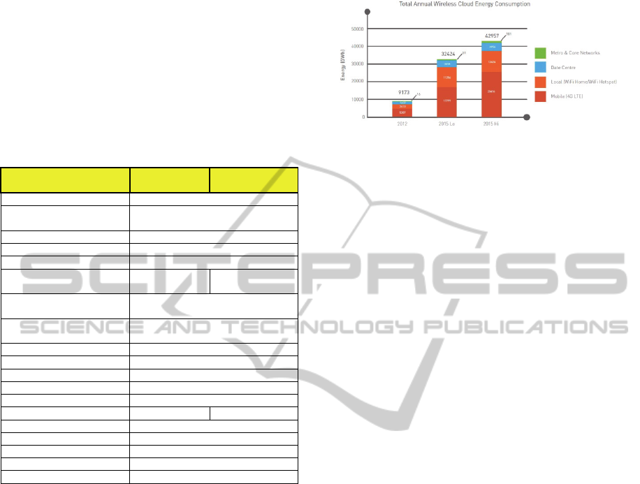
It’s discussed in (Bell Labs and University of
Melbourne, 2013) that Mobile networks, and
especially their radio access parts (frontend to user),
are by far the dominant and most concerning drain
on energy in the entire clouding system. The energy
calculations show that by 2015 wireless cloud will
consume up to 43 TWh in comparison to only 9.2
TWh in 2012. That is an increase of 460% which is
in carbon footprint from 6 megatons of CO2 in 2012
up to 30 megatons of CO2 in 2015. Figure 3 shows
up to 90% of this consumption is attributable to
mobile and access networks (data centers account
for only 9%).
Therefore, the focus should be on making cloud
systems more energy-efficient by developing more
energy-efficient radio access network technologies
and specifically the upfront ones like small and
femtocells.
Figure 3: Estimate for annual energy consumption broken
down into the various components of the wireless cloud
ecosystem, 2012 and 2015 (Lo and Hi scenarios).
In (Al Haddad et al., 2012), a new indicator is
introduced which enables us to calculate the
consumed CO2 emission per kWh and enlighten the
green effect of any technology based saved energy
amount. The kWh is converted to kg of carbon
saved. For instance, the conversion factor for the
United States is 0.62747 kg CO2 saved for each
kWh produced from a carbon free source.
The factor is based on the carbon emissions
generated by the current United States' power
stations per kWh generated. This factor includes
other greenhouse gasses such as methane and nitrous
oxide which are converted to their carbon dioxide
equivalents so the value is really kg CO2 eq. per
kWh. The CO2 consumption can be calculated as
shown in the following equation:
CO2Power
Watt
∗ Conversionfactor
(4)
5 ANALYSIS OF FEMTOCELL
DEPLOYMENT IN CELLULAR
NETWORKS
In heterogeneous networks, where high data rates
are desired, more dense deployment of femtocells is
seen as an enabling solution. They are deployed with
the macrocells in an overlay, overlapping or
disjointed area in cellular networks. With such
hyper-dense networks, the problem of interference
comes between the macro cells and small cells as
well as among the small cells themselves. The
interference between macrocell and femtocell, i.e.,
inter-tier interference, arises from the fact that
femtocells may utilize the spectrum already
allocated to the macrocell. Without proper
interference management, significant power is likely
to be wasted in order to maintain an acceptable user
performance.
Main challenges with femtocell Technology are
SMARTGREENS2014-3rdInternationalConferenceonSmartGridsandGreenITSystems
250

the Coordination between macrocells and ad-hoc
femtocells, Interference mitigation with macrocells
and femtocell deployment in a power-aware and
green way. Further challenges to be considered with
femto technology:
Tx Power Management: the RF environment is
constantly changing and each femtocell needs to
adapt its transmit power as other cells are being
added, relocated or removed to maintain a
continuous coverage and avoid interference.
Location Uncertainty: the location of femtocell is
randomness and unpredictable, and as the owner
likes.
Configuration Variation: some femtocells
configuration parameters might be adjusted by the
owners for operation and performance. The degree
of uncertainty in the deployment increases if the
femtocells configuration could be set differently for
each femtocell.
Access and Security Control: OSG (Open
Subscriber Group) or CSG (Closed Subscriber
Group). Different access control mechanisms for
femtocells may result in different interference
environments much more complicated to control
than that of the conventional wireless cellular
networks.
Resource and Interference Management:
femtocells can operate in their own dedicated
channel or share a channel (co-channel) with the
existing network cells. Femtocells deployed in co-
channel manner as macro cells need to coordinate
with macro cells to determine the optimal resource
partitioning and maximize traffic offloading to
femtocells.
Mobility Management: femtocells need to discover
neighbors autonomously to facilitate UE handover.
Backhaul Management: bandwidth of customer
backhaul cannot be guaranteed. When femtocells
experience limitation in backhaul bandwidth, they
should prioritize user classes or transferred packets.
All in all, Introducing femtocells should not
significantly degrade the performance of other/prior
deployed networks, therefore all the above listed
challenges should be considered and solved.
6 INTERFERENCE
MANAGEMENT TECHNIQUES
FROM POWER CONTROL
PROSPECTIVE
It is crucial to mitigate the interference which arises
when femtocells are deployed in macrocell networks
and ensure that the spectral efficiency is better than
that of the macrocell only networks. Several
interference management schemes for cellular
networks with femtocells are presented.
Optimization of Resource Allocation in case of
coexisting femtocell and macrocell network
(cognitive radio) like analyzed in (Femto Forum
Working Group, 2009); (Boudec, 2012); (Luo
and Yu, 2006) or by utilizing new features like
“range expansion” that allows a User Equipment
(UE) to be served by a cell with weaker received
power (3GPP R4-092042, 2009) (RP – 111369,
2011).
Radio resource coordination by allocating
different resources between neighboring eNBs in
the time or frequency domains as shown in
(3GPP R4-093349, 2009).
System/Design improvement by adding more
resources like MIMO design as shown in (Cui et
al., 2004).
Dynamic Resource Management where new
techniques like “opportunistic small cells” are
introduced (Qualcomm, 2013), which
dynamically turns the femtocell “ON” or “OFF”
based on the need for capacity for instance
proximity of users or traffic status e.g. idle status,
to not only reduce interference but also lower
energy consumption.
Power Control (PC) which is necessary to
mitigate the interference by manipulating the
transmission power settings.
In this chapter we will go through the existing PC-
related solutions only. There are Downlink and
Uplink Power Control techniques for Interference
Mitigation and Power Setting Tuning. In this section
we try to summarize the most recent and important
ones.
6.1 Uplink Power Control
In the uplink (UL), the interference from the outdoor
Home UE to the macro eNB becomes a serious
problem when the Home UE is located close to the
macro eNB. In this case, the transmit power from
Home UE has to be reduced in order to mitigate
such interference. On the other hand, the indoor
Home UE, which is close to its serving Home eNB
and far from the macro eNB, can increase transmit
power with a bit or even no interference to macro
eNBs. Therefore, it is necessary to apply the uplink
power control in femtocell networks.
The uplink power control for LTE as currently
EvaluationofFemtocellTechnologyChallengesandItsPowerControlMethodologiesforGreenHeterogeneousNetworks
251

defined in 3GPP standards (3GPP TS 36.213, 2013)
is composed of open and closed loop components.
The open loop power control (OLPC) is responsible
for a rough setting of UE transmit power. It
compensates slow changes of pathloss (including
shadowing) in order to achieve a certain mean
received signal power for all users. The closed loop
power control (CLPC) is used for user specific
adjustments of the power settings considering such
factors as Modulation and Coding Scheme (MCS),
measurement errors and rapid changes in radio
conditions. It can be also used for further
optimization of general network performance, as e.g.
described in (Boussif, 2008); (Boussif, 2010). The
equation defined in 3GPP for setting transmit power
of Physical Uplink Shared Channel (PUSCH) is as
follows (dB scale):
P
min
PMax,10log
M
P0αPL
deltaMCS
f
deltai
(5)
[Where PMax is the maximum allowed UE transmit
power, M is the number of Physical Resource
Blocks (PRB) scheduled for the given user in a time
slot, P0 is parameter related to target mean received
power (user or cell specific), α is pathloss
compensation factor (cell specific), PL is the
downlink pathloss measured by the UE
(3GPP TS
25.814, 2006), deltaMCS is a parameter depending on
the used MCS (user specific), and f(deltai) is a user
specific CLPC correction]. In this case the cell
specific parameters of the OLPC are considered (P0,
α) as they have the main impact on the inter-cell
interference.
If this simple power control method is applied in
the uplink, a too strong signal transmitted from the
outdoor Home UE possibly can cause interference to
nearby macro eNB(s). In order to deal with this
problem, the PL between Home UE and its nearest
neighbor macro eNB has to be estimated for
additional actions. Some well-known methods
developed for uplink power control are:
Power Cap Based PC: the maximum
transmission power density (i.e., power cap) of the
HUE is restricted in order to avoid heavy
interference to macro eNB(s). The power cap of the
HUE is calculated as a function of the estimated PL
between HUE and its nearest neighbor macro eNB.
Then, the HUE is power-controlled based on the PL
from the HUE to its serving Home eNB, up to the
level of the power cap (3GPP TS 36.104, 2007).
PL Difference based PC: with the knowledge of
the difference between the PL from the Home
UE to its serving Home eNB and its nearest
neighbor macro eNB, the Home eNB calculates
the power offset as a non-decreasing function of
the PL difference. Then, this offset value is sent
to the Home UE via a radio resource control
message to further adjust the uplink transmission
power. Based on these facts, the Home UE
transmit power can be adjusted accordingly
(3GPP TS 36.104, 2007).
Adaptive Target Mean received po>Wer
(Adaptive P0): the proposed solution in (Jacek,
Pedersen, Szufarska and Strzyz, 2010) is to
define the OLPC parameter P0 in equation (5) in
a way that would reflect the distribution of
interference levels within macrocell, e.g. as a
function of pathloss towards closest macro-eNB:
P0 round
APo BPoPLLA
(6)
[Where P0 is the calculated OLPC parameter for a
local area node, PLLA_WA is the downlink pathloss
to the closest wide area node. APo and BPo are
parameters of the function that can be e.g. operator
or vendor specific]. The algorithm introduces two
additional parameters (APo, BPo are the same for all
Home eNBs) but it allows full individual
configuration too. To achieve similar effect with the
basic OLPC procedure, each local cell would have to
be configured with an individual set of parameters.
Link Budget Analysis: a link budget analysis is
provided which enables simple and accurate
performance insights in heterogeneous networks.
In
(Chandrasekhar, Andrews, Muharemovic, Shen,
and Gatherer, 2009),
a distributed utility-based
SINR adaptation at femtocells is proposed in
order to alleviate cross-tier interference at the
macrocell from co-channel femtocells. The
Foschini-Miljanic (FM) algorithm is a special
case of the adaptation. Each femtocell maximizes
their individual utility consisting of a SINR
based reward less an incurred cost (interference
to the macrocell). The radio link quality for a
cellular user is determined, given a set of N
transmitting femtocells with different SINR
targets. Achieving higher SINR targets in one
tier fundamentally constricts the highest SINRs
obtainable in the other tier.
6.2 Downlink Power Control
Several interference mitigation schemes using
femtocell BS power level setting in DL have been
investigated:
Basic fixed Power Approach: it is based on a
preconfigured value which is common for all
SMARTGREENS2014-3rdInternationalConferenceonSmartGridsandGreenITSystems
252

femtocell BSs regardless of the surrounding RF
conditions. Advantages of this scheme are its
simplicity and ease of implementation.
Disadvantages are its difficulty to adapt to the
surrounding RF conditions and likeliness to
cause large interference. If the fixed power level
is too low, the femtocell BSs located close to the
macrocell BS have poor coverage because the
interference from the macrocell BS is high. On
the other hand, if the fixed power level is too
high, the femtocell BSs located at edge of the
macrocell provide a large interference to the near
macrocell MSs because the interference from the
femtocell BSs to the macro MSs becomes high.
Self-configuration based on Macrocell BS
Signal: self-configuration of transmit power
level based on the measured received signal level
from the macrocell BS was developed by
Claussen et al., (2008).
Self-optimization Approach based on SINR: a
self-optimization of coverage in accordance with
the information on mobility events of passing
and indoor users is used. Li et al., (2009) used
downlink power control to achieve SINR for
both macrocell and femtocell users.
Guidelines on how to control UMTS Home NodeB
(HNB) and LTE Home eNodeB (Home eNB)
interference by transmit power level setting are
given in
(3GPP TR 25.967, 2012) (3GPP TR 36.921,
2012). However, the previous techniques have not
adequately accounted for the interference with
neighboring macrocell users and surrounding
conditions.
RSRP Approach: the largest Reference Signal
Received Power (RSRP) corresponding to the
nearest macro eNB is used as one of the
parameters for tuning downlink power control
(3GPP R4-093557, 2009). As the RSRP
decreases, which means that the Home eNB is
located close to the edge of the macro cell, the
transmit power should be small in order to
mitigate the downlink interference to the macro
UE. If a Home eNB is close to a macro UE,
lower transmit power should be set to mitigate its
interference to the macro UE. With the
knowledge of the largest RSRP and power offset,
the Home eNB selects the transmit power of the
reference signal as the median values of the sum
of the largest RSRP and power offset, the lower
and the upper limit values of transmit power.
Adaptive power level setting approach: two
adaptive power level setting schemes are
possible here as shown in (3GPP TR 36.814,
2010):
a) Adaptation based on DL Reception Power
from MBS:
This technique is based on downlink co-channel
reception power of the reference signal of the
strongest macrocell BS. The femtocell BS measures
the reception power at the initial configuration phase
or in operational phase and adaptively set the
transmit power level accordingly. This scheme
corresponds to the measurement based self-
configuration scheme given in (Morita, Matsunaga,
and Hamabe, 2010). The femtocell BS sets the
transmit power of the reference signal as:
P
_
MEDIANP
P
,P
_
_
,P
_
_
(7)
[Where the function MEDIAN() means the returned
value is the median of all arguments. P
[dBm] is the
reception power of the reference signal from the
nearest macrocell BS measured at the femtocell BS
and is dependent on the path loss between the
nearest macrocell BS and the femtocell BS which
includes the penetration loss at the building wall.
P
[dB] is the predetermined fixed power offset
compensating for the indoor loss. P
__
and
P
__
[dB] are the upper and the lower limit value
of the transmit power. P
__
is needed to limit the
interference from the femtocell BS to the macrocell
MS. P
__
is also needed to guarantee a certain
minimum performance for femtocell even if the
surrounding macrocell cannot be detected].
A disadvantage of the schema is that it is not
enough for only fixed power offset to compensate
for the indoor path loss. Each building has different
properties, such as the penetration loss at external
walls and P
should be tuned accordingly.
b) Adaptation based on DL Reception Power from
macrocell BS and UL Reception Power from
macrocell MS:
This technique is based on downlink (DL) co-
channel reception power of the reference signal of
the strongest macrocell BS and uplink (UL)
reception power from neighboring macrocell MSs.
The femtocell BS adaptively measures the DL and
UL reception power at self-configuration phase and
then optimizes the transmit power during the self-
optimization phase. The femtocell BS sets the
transmit power of the reference signal as follows:
P
_
MEDIANP
P
_
_
K
∗L
,P
_
_
,P
_
_
(8)
[Where P
, P
__
, and P
__
have the same
meaning as (7). P
__
[dB] is a predetermined
EvaluationofFemtocellTechnologyChallengesandItsPowerControlMethodologiesforGreenHeterogeneousNetworks
253

power offset value compensating for the indoor path
loss excluding the penetration loss.
is an
adjustable positive factor and can be determined by
the priority of the femtocell BS operation. L
[dB] is
the penetration loss which assumed to be ideally
estimated]. A macrocell MS is assumed to be located
in close proximity to a femtocell BS. This means the
distance from the macrocell BS to the macrocell MS
is nearly the same as that from the macrocell BS to
the femtocell BS. The penetration loss L
can be
calculated as follows:
L
1
2
∗P
_
P
_
L
(9)
[Where P
_
[dBm] is the UL transmit power
virtually calculated by the femtocell BS. P
_
[dBm]
is the UL reception power from the macrocell MS
measured at the femtocell BS. L
[dB] is open - air
propagation loss between the macrocell MS and the
femtocell BS excluding the penetration loss]. L
is a
predetermined value and is assumed in advance so
that the distance between the macrocell MS and the
femtocell BS can be minimized under the conditions
in which the interference from the macrocell MS to
the femtocell BS is tolerable. When the path loss
between the macrocell MS and the femtocell BS
excluding the penetration loss is within La, the
penetration loss in equation (9) is estimated to be
smaller than its real value and the transmit power is
suppressed. When the path loss is outside L
, the
penetration loss is estimated to larger than the real
value and the transmit power is released. This power
setting technique can resolve the problem of the last
power setting schema.
Auto-tuning of DL Power of Femtocells
Adaptive to Various Interference Conditions:
the power offset in previous introduced
technique has not been adequately optimized for
various interference conditions. In (Kan et al.,
2011), the proposed scheme automatically tunes
the power offset so that the femtocell throughput
can increase while maintaining the macrocell
throughput based on macrocell mobile stations’
interference detection reports. In comparison to
the last technique where the
__
is fixed,
various interference conditions such as size of
buildings where femtocell mobile stations exist
and distance to a street where macro MSs exist
are not sufficiently considered. The macrocell or
femtocell throughput may degrade if the initial
value is too large and too small compared with
the conditions.
Therefore, (Kan et al., 2011) introduces different
auto-tuning schemes using individual offset where
the P
__
is tuned individually per femto BS or
using common offset where the P
__
is tuned
commonly among femto BSs in a macrocell with
per-femtocell or per-macrocell measurement,
respectively. This approach uses a stepwise tuning
of P
__
based on Interference Detection Ratio
(IDR1) indicator, which is the ratio of the number of
interference detection reports to the number of
macro MSs that receive the measurement control
message from the serving macro BS.
7 CONCLUSIONS
With the steadily increasing demand for mobile
traffic, it is important that the telecom networks are
modernized with all the capacity, quality and
coverage extension technologies available and
especially the energy efficient ones such as
femtocell technology. In 3G networks, small cells
are viewed as an offload technique whereas from 4G
networks onwards, the principal of heterogeneous
networks is introduced where the network is based
on layers of small and large cells together. Whether
it’s a low indoor coverage, bad network performance
in rural areas, required capacity increase and high
data rates or qualified coverage guarantee in hard-to-
cover areas, a cost-efficient way to address these
issues is femtocell solutions.
There are no distinct standards to define the
physical power transmission of a femtocell but only
recommendations. This survey work provides an
overview of the power control and saving
methodologies with regard to femtocell technology.
It also discusses its challenges and different potential
ideas for improvements. The femtocell technology is
still young and fertile research is still required here.
In our future research work, we will be further
identifying the ability for femtocell technology to
help with the green initiatives. For instance, future
network releases need to support the coordination
among femtocells and not only between macro and
femto cells and take into account conditions of both
surrounding environment and networks. In addition,
other topics will be further investigated like
enhancing existing power control methodologies,
powering down small cells based on traffic situation,
improvements on cell phone battery life and
throttling small cell power down based on cell type
and usage.
Future innovations and further research are
strongly required to overcome the challenges
coming with this immature technology.
SMARTGREENS2014-3rdInternationalConferenceonSmartGridsandGreenITSystems
254

ACKNOWLEDGEMENTS
To my university advisor for his great efforts of
supervising and leading us, to accomplish this work.
To every person who gave us something to light our
pathway, we thank them for their support,
encouragement and believing in us.
REFERENCES
Bell Labs and university of Melbourne (2013), "The
Power of Wireless Cloud" An analysis of the energy
consumption of wireless cloud – CEET.
D. N. Knisely, T. Yoshizawa, F. Favichia (2009),
“Standardization of femtocells in 3GPP,” IEEE
Communications Magazine, vol.47, no.9, pp. 68-75.
3GPP TR 36.814, v2.0.0 (2010), “Further Advancements
for E-UTRA, Physical Layer Aspects”.
Kan Zheng; Yuyu Wang; Wenbo Wang; Dohler, M.;
Jianquan Wang (2011), "Energy-efficient wireless in-
home: the need for interference-controlled femtocells"
Wireless Communications, IEEE.
ABI Research, Picochip, Airvana, IP.access, Gartner,
Telefonica Espana (2007), 2nd International
Conference on Home Access Points and Femtocells
The Small Cell Forum (2013), - formerly the Femto
Forum:http://www.smallcellforum.org/aboutsmallcells
-small-cells-what-is-a-small-cell.
M.–S Alouini and A. J. Goldsmith (1999), “Area Spectral
Efficiency of Cellular Mobile Radio Systems,” IEEE
Transactions on Vehicular Technology.
Analysys Research Limited (2007), “Picocells and
Femtocells: Will indoor base-stations transform the
telecoms industry?”.
Giuseppe Piro, Luigi Alfredo Grieco, Gennaro Boggia,
Francesco Capozzi, and Pietro Camarda" (2011),
Simulating LTE Cellular Systems: an Open Source
Framework", IEEE Trans. Veh. Technol., vol. 60, no.
2.
Al Haddad, Mazen, ElSayed, Zaghloul, Bayoumi, Magdy
(2012): Center for Advanced Computer Studies,
University of Louisiana at Lafayette, USA, "Green
arithmetic logic unit", ICEAC.
Femto Forum Working Group (2009), “OFDMA
Interference Study: Evaluation Methodology
Document.
Jean-Yves Boudec (2012), “Rate adaptation, Congestion
Control and Fairness”.
Z. Luo, W. Yu (2006), “An Introduction to Convex
Optimization for Communication and Signal
Processing,” IEEE Journal on Selected Areas in
Communications, vol. 24, no. 8, pp.
3GPP R4-093349 (2009), “Femtocell and Macrocell
interference coordination based on SFR,” Motorola,
RAN WG4 #52.
Shuguang Cui, Andrea J. Goldsmith, and Ahmad Bahai
(2004), “Energy-Efficiency of MIMO and Cooperative
MIMO Techniques in Sensor Networks” IEEE
Journal on Selected Areas in Communications, vol.
22.
3GPP R4-092042 (2009), “Simulation assumptions and
parameters for FDD HeNB RF requirements,” Alcatel-
Lucent, picoChip Designs and Vodafone.
RP – 111369 (2011), “Further enhanced non CA-based
ICIC for LTE,”3GPP TSG RAN Meeting #53,
Fukuoka, Japan.
Qualcomm (2013), http://www.qualcomm.com/research/
projects/lte-advanced/opportunistic-small-cells
3GPP TS 36.213 (2013), “E-UTRA – Physical layer
procedures”.
M.Boussif, et al. (2008), “Interference Based Power
Control Performance in LTE Uplink”, ISWCS,
Reykjavik, Iceland.
M.Boussif, et al.(2010), “Load Adaptive Power Control in
LTE Uplink”, European Wireless 2010, Lucca, Italy
3GPP TS 25.814 (2006), “Physical layer aspects for
evolved Universal Terrestrial Radio Access (UTRA)”,
v7.1.0.
3GPP TS 36.104 (2007), Evolved Universal Terrestrial
Radio Access (E-UTRA); Base Station (BS) radio
transmission and reception; Release 9.
Góra Jacek, Klaus I. Pedersen, Agnieszka Szufarska,
Stanislaw Strzyz (2010), "Cell-Specific Uplink Power
Control for Heterogeneous Networks in LTE"
Vehicular Technology Conference Fall (VTC 2010-
Fall), IEEE 72
nd
.
Vikram Chandrasekhar, Jeffrey G. Andrews, Tarik
Muharemovic, Zukang Shen, Alan Gatherer (2009),
“Power Control in Two-Tier Femtocell Networks” -
IEEE Transactions On Wireless Communications, vol.
8, NO. 8.
Holger Claussen, Lester T. W. Ho, and Louis G. Samuel
(2008), “Selfoptimization of Coverage for Femtocell
Deployments,” Wireless Telecomunications
Symposium (WTS), pp.278.
Xiangfang Li, Lijun Qian, and Deepak Kataria (2009),
“Downlink Power Control in Co-Channel Macrocell
Femtocell Overlay” CISS, pp.383.
3GPP TR 25.967 (2012), “Home Node B Radio Frequency
(RF) Requirements (FDD) (Release 9)” v9.0.0.
3GPP TR 36.921 (2012), “FDD Home eNode B (HeNB)
Radio Frequency (RF) requirements analysis (Release
9),” v9.0.0.
3GPP R4-093557 (2009), “HeNB to Macro eNB
Downlink Interference Mitigation with Power
Control”
Motoki Morita, Yasuhiko Matsunaga, Kojiro Hamabe
(2010), "Adaptive Power Level Setting of Femtocell
Base Stations for Mitigating Interference with
Macrocells" - Vehicular Technology Conference Fall
(VTC 2010-Fall), IEEE 72
nd
.
EvaluationofFemtocellTechnologyChallengesandItsPowerControlMethodologiesforGreenHeterogeneousNetworks
255
