
Measured Firmware Deployment for Embedded Microcontroller
Platforms
Samuel Weiser, Ronald Toegl and Johannes Winter
Institute for Applied Information Processing and Communications (IAIK), Graz University of Technology, Inffeldgasse 16a,
A–8010 Graz, Austria
Keywords:
Trusted Computing, Embedded Systems, Trusted Boot, Measured Firmware Update.
Abstract:
While Embedded Systems are small hardware systems, much added value is often created through the in-
clusion of specialized firmware. One specific challenge is the secure distribution and update of application-
specific software. Using a Trusted Platform Module we implement measured firmware updates on a low-
resource embedded micro-controller platform. We show that it is feasible to ensure both, confidentiality of the
update and authenticity of the device for which the update was intended. Furthermore a Trusted Boot mech-
anism enforces integrity checks during startup to detect malicious code before it is executed. While recent
literature focuses on high-performance micro-controller systems or FPGA platforms, our proof-of-concept
only requires an 8-bit low-cost off-the-shelf micro-controller.
1 INTRODUCTION
Embedded Systems take many forms, such as indus-
trial control systems, network devices, sensor nodes,
and smart cards. Having become nearly ubiquitous,
the world Embedded Systems market exceeds 100 bil-
lion USD (Global Industry Analysts Inc., 2013) per
annum. Often, sensitive information is created, ac-
cessed, manipulated, stored, and communicated on
such Embedded Systems. Thus, security needs to be
considered throughout the design process (Ravi et al.,
2004), including hardware design and software de-
ployment. This underlines the need for a secure dis-
tribution and installation of firmware both at manu-
facturing time and later when the platform has been
deployed.
A first, important requisite to ensure a secure
firmware life-cycle is to measure what code is de-
ployed on the embedded system. In this paper we
focus on employing Trusted Computing (TC) mecha-
nisms for building a cryptographically measured soft-
ware execution chain on a very small sensor-node
class embedded system.
In Trusted Computing security is bootstrapped
from an extra, small dedicated piece of secure hard-
ware, the Trusted Platform Module (TPM). The TPM
serves as a hardware root of trust, as it is a tamper-
resilient cryptographic chip, which in essence pro-
vides robust cryptographic algorithms including RSA
and SHA-1, a random number generator as well as
secure key storage (TCG, 2013a; Mueller, 2008).
This enables us to ensure integrity of application
specific code, as well as of the platform firmware. In
addition, our scheme ensures the confidentiality of the
firmware.
Our concept allows for instance integration into
an outsourced manufacturing process of the platform
where confidentiality of the Application, i.e. the code
that represents the Intellectual Property (IP) specific
to a field of application, is crucial. The TPM on each
manufactured device owns unique keys that allow tar-
geted Application Updates which are cryptographi-
cally bound to one specific device. In such a set-
ting, breaking the keys of one device will not open
the firmware of the whole series manufactured.
We demonstrate our architecture on a small,
micro-controller-class embedded system which in-
cludes a TPM. We implement a measured boot mech-
anism as well as a process for trusted firmware up-
dates. Our proof-of-concept prototype is validated
against a concrete use case scenario. The presented
platform requires much less resources than related
work while still providing Common Criteria EAL-4
certified security mechanisms.
Related Work. In (Koopman, 2004), several se-
curity issues regarding embedded systems are high-
lighted. Hwang et al. introduce an approach of how to
237
Weiser S., Toegl R. and Winter J..
Measured Firmware Deployment for Embedded Microcontroller Platforms.
DOI: 10.5220/0004877702370246
In Proceedings of the 4th International Conference on Pervasive and Embedded Computing and Communication Systems (MeSeCCS-2014), pages
237-246
ISBN: 978-989-758-000-0
Copyright
c
2014 SCITEPRESS (Science and Technology Publications, Lda.)

abstract embedded system security into multiple lay-
ers (Hwang et al., 2006). Papa et al. deal with the
correct placement of a hardware trust anchor in em-
bedded systems (Papa et al., 2011). Feller et al. place
a TinyTPM implementation into an FPGA, which
comes with relatively low resource overhead (Feller
et al., 2011). Recent work demonstrated a TPM on
a relatively powerful Beagle-board securely booting
a Linux kernel (Larbig et al., 2013). In compari-
son, we use a low-resource, low-cost Atmel Xmega
micro-controller without off-the-shelf operating sys-
tem. One threat orthogonal to the work presented in
this paper is the known susceptibility of many off-the-
shelf micro-controllers to side channel attacks (Kizh-
vatov, 2009).
Outline. The following section explains TPMs and
their integration into small embedded systems. Next
we discuss the used hardware platform followed by
a detailed description of the firmware architecture of
our implementation. Then we give a possible use case
scenario of how to secure firmware in a multi-party
manufacturing process. The final sections deal with
implementation details and summarize the achieved
results.
2 TRUSTED PLATFORM
MODULE
2.1 The TPM as Root-of-Trust
Trusted Computing as it exists today is defined by
the specifications of the Trusted Computing Group
1
(TCG). A hardware component, the Trusted Platform
Module (TPM) (TCG, 2011), is integrated into com-
monly available PCs. So far, hundreds of millions of
platforms have been shipped. Similar to a smart card
a TPM features cryptographic primitives but is physi-
cally bound to its host platform. It contains a tamper-
resilient integrated circuit that implements public-key
cryptography, key generation, secure hashing, secure
storage, and random-number generation. Using these
components, the TPM can enforce security policies
on hierarchies of secret keys to protect the keys from
any remote (software) attacks. As hardware secu-
rity modules, TPMs are intensely tested before they
get certified. Infineon, for instance, offers TCG-
compliant TPMs with a security certification accord-
ing to Common Criteria EAL-4.
A TPM can be used to perform cryptographic
signatures on user-provided data using hardware-
1
http://www.trustedcomputinggroup.org
protected private keys. However, due to limited TPM
resources, keys have to be swapped out of the TPM
when not in use. On PCs this is achieved through a
number of complex support libraries, the TCG Soft-
ware Stack. To protect these keys, a parent storage
key specified upon key creation is used to wrap the
private part of the child key when it is exported from
the TPM. At the top of the key hierarchy is the stor-
age root key which is created when the device’s owner
initially sets up the TPM. Only after this procedure of
taking ownership, the full functionality of the TPM
is available. Clearing ownership is a non-reversible
mechanism to revoke all user-created keys. Keys are
assigned a user-supplied secret, which is used in sev-
eral authentication protocols, and optionally a system
state that must be attained before using the key for
cryptographic operations.
Another key feature of the TPM is to record the
current system state. The TPM measures each soft-
ware component as it is loaded, by cryptographically
hashing the component and storing the resulting mea-
surement value in a specially-protectedPlatform Con-
figuration Register (PCR). PCRs can only be written
to via the one-way extend operation. PCRs are reset
at device boot. For each measurement, a PCR with
index i, in state t is extended with input x by setting
PCR
t+1
i
= SHA-1(PCR
t
i
||x).
PCRs can be used to exactly describe the software ex-
ecuted on a machine by following the transitive trust
model, in which each software component is respon-
sible for measuring its successor before handing over
control. Each caller computes a hash value and ex-
tends a PCR with the result, before any subsequent ex-
ecutable code is allowed to run. In the case of Desktop
computers, this is done starting from the BIOS, cov-
ering boot loader, kernel, and system libraries etc., up
to application code.
Ultimately, a chain of trust is established in which
the exact configuration of the device is mapped to a
set of PCR values. If such a PCR configuration ful-
fills the given security or policy requirements, we re-
fer to the system state as a trusted state. In the Quote
operation, the TPM signs these values together with
a supplied nonce, thus enabling more complex proto-
cols such as Remote Attestation (Chen et al., 2006).
Here, a remote verifier can analyze the result and de-
cide whether to trust the configuration for a given pur-
pose or not.
The TPM can also bind data to a device by en-
crypting it with a non-migratable key. Such a key
cannot be extracted from the TPM’s protected storage
in plain nor can it be moved to another TPM. An ex-
tension to Binding is Sealing. Data may be sealed to a
specific set of values of the PCRs of a specific TPM.
PECCS2014-InternationalConferenceonPervasiveandEmbeddedComputingandCommunicationSystems
238

Thus, access to the data can be restricted to a single
trusted state of the TPM’s host platform.
2.2 Integration in Small Embedded
Systems
When considering trusted embedded platforms we
have to distinguish two classes of platforms: The first
class of trusted embedded platforms, including many
industrial PC motherboards, is typically based on x86
compatible processors and includes a PC-style South-
bridge controller which exposes an LPC bus interface.
On this class of trusted embedded platforms the TPM
is connected to the system using the LPC bus inter-
face. Trusted embedded platforms in this category
can be treated exactly in the same manner as desktop
PC platforms without any loss of generality. Com-
plex drivers and library infrastructures are available
for mainstream PC operating systems.
The following sections, however, focus on a sec-
ond class of trusted embedded platforms, which do
not provide a standard LPC bus interface and thus
have to resort to alternative methods for connecting
to a TPM. Also, those platforms are typically more
resource restrained and require more efficient, tailor
made software implementations.
Recently, TPM vendors introduced chips offering
SPI or I
2
C bus interfaces for the integration in em-
bedded systems. We concentrate our discussion on
TPMs connected via an I
2
C bus. This bus is supported
by virtually any embedded microprocessor or micro-
controller of interest, either through dedicated hard-
ware blocks or throughsoftware-emulationusing gen-
eral purpose input/output pins. The inter-IC (I
2
C) bus
(NXP semiconductors, 2012) provides a simple bidi-
rectional half-duplex 2-wire interface for communi-
cation between micro-controllers and other integrated
circuits (ICs). Data transfers are 8-bit oriented and
can reach speeds of up to 100 kbit/s in standard mode
or 400 kbit/s in fast mode. Higher transfer speeds up
to 5 Mbit/s can be achieved given that certain hard-
ware constraints are met.
Physically the I
2
C is implemented using a bidirec-
tional clock line (SCL) and a bidirectional data line
(SDA). Both signal wires are implemented as open-
drain outputs, which are pulled up to supply voltage
through a resistor. To drive a logic 0 on one of the
bus line, a device activates its output transistor to cre-
ate a low impedance path between the bus line and
ground. A logic 1 can be driven on the bus lines if
all devices connected to the bus deactivate their out-
put transistors, thus preventing a low impedance path
between the bus lines and ground. As a consequence
the values observed on the SDA and SCL bus lines
are determined by the logical AND of values driven
by all connected devices - the bus actually acts like a
large wired-AND gate.
Communication is always initiated by a master de-
vice, like a microprocessor, which provides the basic
clock signal on the SCL line. Slave devices, like for
example an EEPROM memory or a TPM, can stretch
the bus clock by driving driving a logic zero on the
SCL line. Each slave device on the I
2
C has an 8-bit or
10-bit device address which can is used to uniquely
identify the device on that bus segment. The 10-
bit address format is designed to be compatible with
slave devices which understand 8-bit addresses only.
Currently no approved publicly available TCG
standard for TPMs with I
2
C interface exists, al-
though several vendors have recently started ship-
ping I
2
C-enabled TPMs. The TCG’s Embedded Sys-
tems Working Group works on a currently unreleased
draft for a I
2
C TPM interface specification based on
the existing PC-centric TPM TIS (Trusted Computing
Group, 2011) specification. At the time of this writing
no final standard has been published yet.
3 HARDWARE PLATFORM
In an earlier paper (Pirker et al., 2012) we briefly
discussed how standard desktop TPMs with an LPC
bus interface can be integrated on embedded (ARM)
system platforms using customized FPGA hardware.
The platform discussed in (Pirker et al., 2012) is very
similar to many current smart-phones and tablets, and
resides on the powerful end of the embedded sys-
tems spectrum. In this paper we want to focus on
Trusted Computing for the opposite side of the em-
bedded systems spectrum, smaller devices based on
standard-compliant off-the-shelf components, which,
apart from the Trusted Platform Module itself, do not
require any special purpose hardware like FPGAs, yet
offer cryptographic mechanisms which are tamper re-
silient.
This section now discusses the hardware details
of the “GUSTL” trusted embedded systems evalua-
tion platform shown in Figure 1, which we use to
prototype the trusted firmware update mechanism dis-
cussed in this paper. The GUSTL hardware platform
has been developed by us, to specifically enable ex-
perimentation and research on small, low-resource,
trusted embedded system. GUSTL models a typical
low-resource embedded system, as it may be used for
embedded control and sensing applications. In con-
trast to other trusted embedded system research plat-
forms, such as the Linux-based system discussed in
(Larbig et al., 2013) and the Android-based system
MeasuredFirmwareDeploymentforEmbeddedMicrocontrollerPlatforms
239

discussed in (Pirker et al., 2012), we focus on small
platforms with hardware and software requirements
similar to embedded sensor nodes. Our trusted hard-
ware platform can be used in stand-alone mode, or as
add-on system to a larger host platform.
The heart of the GUSTL evaluation platform is an
8-bit Atmel AVR micro-controller (ATxmega32A4U
(Atmel, 2012)) with a total 36K of on-chip flash mem-
ory for boot code (4K flash) and program code (32K
flash), 4K of on-chip static RAM and 1K of non-
volatile (EEPROM) data memory. The controller in-
cludes a rich set of on-chip peripherals, including
timers, several serial interface blocks (UART, I2C,
SPI), an USB device interface block, analog-to-digital
convertersand digital-to-analog converters. Addition-
ally the AVR controller provides instruction set ex-
tensions for fast (3)DES computation and a dedicated
AES-128 hardware cryptography accelerator.
The ATxmega32A4U micro-controller used on
the GUSTL platform is a RISC processor with a
Harvard-style memory system. Code and data mem-
ory is separated, and code memory can not be ac-
cessed using regular load and store instructions. Em-
bedded firmware running on the controller uses spe-
cial “Load from Program Memory” (
LPM
) and “Store
to Program Memory” (
SPM
) instructions to read from
and write to code memory. The
LPM
instruction is typ-
ically used by firmware to access constant data, such
as static calibration tables or product parameters. The
SPM
instruction, enables in-system programming and
in-system updates of the code memory. Both instruc-
tions use a page-based addressing scheme with a flash
page size of 256 bytes.
Lock bits providea certain level of codeprotection
for the boot-loader and application section of the flash
memory. Both flash sections can be independently
locked. Direct access to the program flash memory
via
LPM
and
SPM
instructions can be prohibited while
code execution is still allowed (Atmel, 2012). It is
for example possible to restrict use of the
SPM
to the
boot-loader section.
Apart from the AVR micro-controller,the GUSTL
hardware platform depicted in Figure 1 includes an
embedded Trusted Platform Module and an additional
EEPROM chip (Atmel ATSHA204) with security and
authentication features. For the experiment discussed
in this paper, we do not use the ATSHA204 EEP-
ROM. The Trusted Platform Module used on the
GUSTL platform is an Infineon SLB 9635 engineer-
ing sample which implements TPM specification ver-
sion 1.2 (TCG, 2011). It comes with an pre-installed
endorsement key and endorsement key (EK) certifi-
cate. The EK is unique for each Trusted Platform
Module and thus gives each GUSTL device a unique
identity. Both chips are connected to the AVR micro-
controller via an I
2
C interface which is clocked at
100kHz.
During firmware update, configuration and diag-
nosis, it is necessary to connect the GUSTL platform
to an external host computer. In this case communica-
tion with the host computer is done over the USB de-
vice interface exposed by the AVR micro-controller.
Apart from a standard Mini-USB cable, no special
hardware is needed to connect the GUSTL platform
to a desktop PC or notebook computer. The Trusted
Firmware Update mechanism later in this paper uses
the USB interface to upload new parts of the firmware
to the GUSTL platform. For in-field operation, the
GUSTL platform does not depend on the USB inter-
face, or the host platform. Depending on the loaded
firmware, the USB interface can be disconnected and
GUSTL can operate in standalone mode, without con-
nection to any host system. In standalone mode, the
firmware loaded onto GUSTL’s micro-controller can
for example use the TPM to keep track of interesting
environmental events by measuring physical sensors
input into the TPM’s PCRs.
GUSTL is a cost-efficient platform designed
around a 3EUR micro-controller and some embed-
ded TPM engineering samples, with parts (excluding
manufacturing costs of the printed circuit board itself)
summing up to less than 10EUR. Still, it offers strong
cryptographic mechanisms and demonstrates a high
level of efficiency in controlling TPMs.
4 ARCHITECTURE OF
FIRMWARE FOR TRUSTED
DEPLOYMENT
4.1 Firmware Architecture
We now present our software architecture for the
firmware which has been designed to allow the trusted
deployment, measurement and update of code to the
GUSTL embedded system. The firmware was devel-
oped during a bachelor thesis (Weiser, 2013).
Our firmware architecture consists of two parts,
which we call the Apploaderand the Application. The
Apploader serves as a kind of boot-loader to receive,
decrypt, measure, update, verify and run an Appli-
cation. The Application is the valuable part of the
firmware IP which needs to be protected. Encryption
ensures that the Application is never transmitted in
plain during the update process.
The Apploader is built on top of the Atmel Soft-
ware Framework (ASF) (Atmel, 2013) as depicted in
PECCS2014-InternationalConferenceonPervasiveandEmbeddedComputingandCommunicationSystems
240
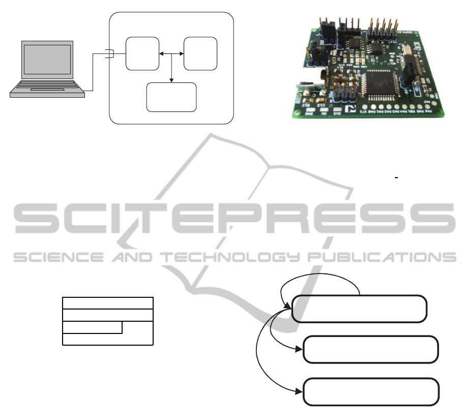
Secure
EEPROM
µC TPM
I²C
USB
GUSTL
Figure 1: GUSTL Platform.
Figure 2. The ASF abstracts access to USB commu-
nication, AES cryptography unit, flash and EEPROM
and is provided by Atmel. The TPM driver connects
to the TPM via I
2
C interface. Our scheme relies on a
TPM as trust anchor and secure environment for stor-
ing and transporting cryptographic key material. Our
scheme avoids use of asymmetric cryptographyon the
main micro-controller of the target device. We rely on
the key hierarchies and the TPM’s binding primitive,
to securely transport firmware encryption and authen-
tication keys to the target device.
Application
Apploader
TPM driver ASF
ASF
Figure 2: Firmware Layout.
4.2 Apploader
The Apploader is the key security element in
firmware. It is responsible for building up a chain of
trust as intended by the TCG.
4.2.1 Core Root of Trust for Measurement
In TC, the Core Root of Trust for Measurement
(CRTM) is the entity responsible for reliably assessing
the device state. If an untrusted software is to be exe-
cuted, the CRTM has to measure it first. This can be
done by simply hashing over the code’s binary. Then
this measurement can be checked to either allow or
decline software execution.
In the TCG concept of a so-called chain of trust
(TCG, 2013a) the CRTM is the trusted anchor from
which trust is extended to other software. Typically,
the CRTM is in the platform’s BIOS, respectively
firmware. Thus it is crucial to its trustworthiness that
the CRTM is protected from modification.
As previously outlined, the TPM’s PCRs allow
us to securely store measurements over the software
being executed. These hashes are stored in PCR
registers via the TPM command TPM
Extend (TCG,
2011). A PCR will only contain the expected value
if all previously measured code was trustworthy on
the one hand and executed in the correct order on the
other hand. Thus, a properly measured chain of trust
reflects the current execution state of the device in its
PCRs.
Run
Run
Application
Application
Application
Application
Update
Update
CRTM
CRTM
-
-
Apploader
Apploader
Figure 3: Chain of Trust.
Such a measurement can be done in several ways.
In our architecture, the Apploader hosts the CRTM
functionality and builds up the chain of trust. While
generalized approaches measure all peripherals for
presence and correct initialization (Hendricks and van
Doorn, 2004), we limit the measurement to a SHA-1
hash over the flash pages that are to be executed. The
Apploader starts measuring itself, then checks the Ap-
plication against a reference measurement and finally
gives control to the Application as depicted in Figure
3. In case of Application Updates the reference mea-
surement is updated to match the new Application.
This Trusted Boot mechanism thus ensures integrity
of the device. To protect the Apploader from mod-
ification the ATxmega boot lock bits (Atmel, 2012)
should be activated.
Furthermore the TPM allows to bind several keys
MeasuredFirmwareDeploymentforEmbeddedMicrocontrollerPlatforms
241

to specific PCR values and thus a safe device state. It
is possible to restrict decryption of Application Up-
date Pages if the Apploader was measured correctly.
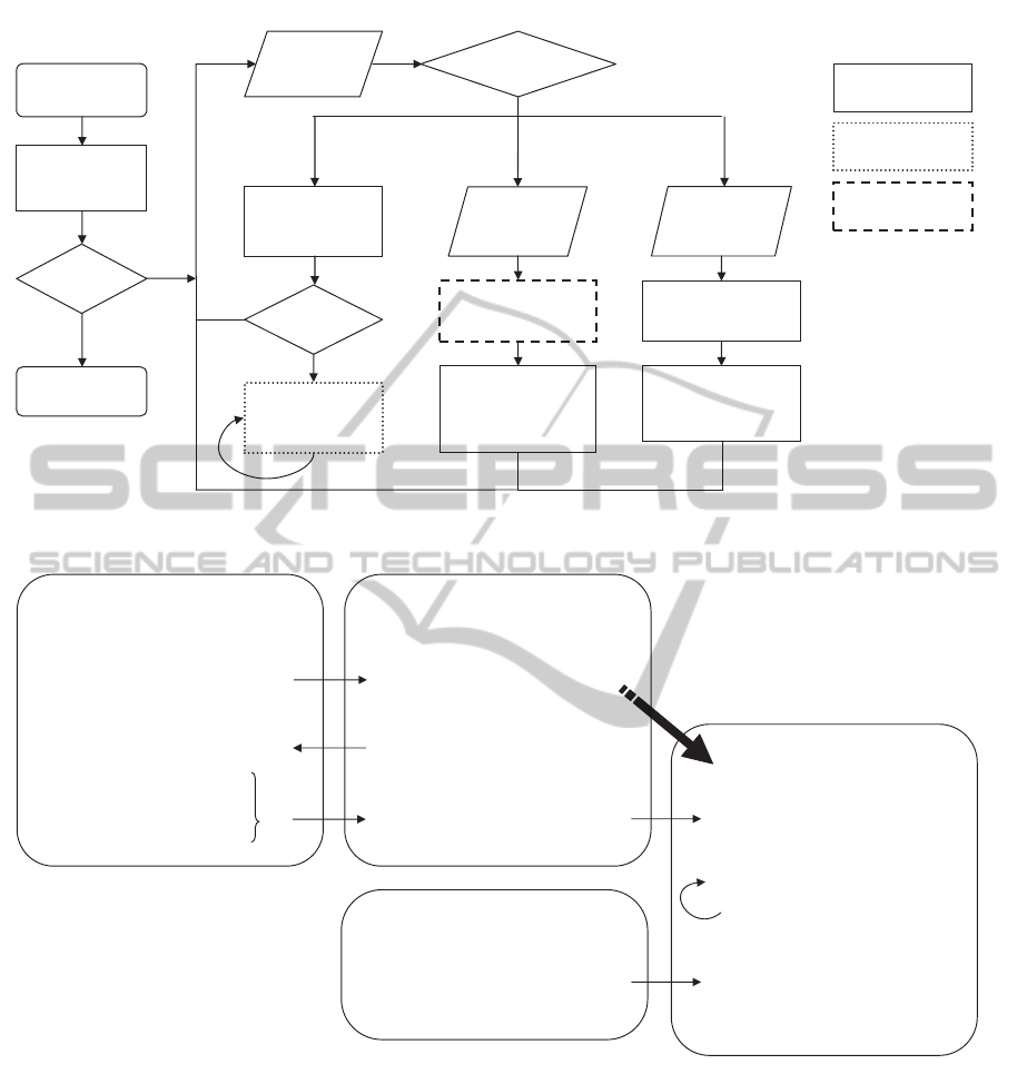
4.2.2 Control Flow
The complete control flow from device reset to updat-
ing and running an Application can be seen in Fig-
ure 4. After hashing over itself the Apploader de-
cides whether to continue or not. Although the Ap-
ploader must not be modifiable at all, this check is
good practice in order to detect bitflips in flash mem-
ory. Such bitflips occur especially in high-radiation
environments or may be induced by a skilled attacker
who wants to compromise the Apploader. After suc-
cessful self-verification the Apploader offers an inter-
face for updating and running an Application. Our
security architecture is therefore enabled through the
following three functionalities:
• run - Measure, verify and run Application
The complete Application flash is hashed and
checked against a reference hash stored in
EEPROM. Only if both hashes match, the Appli-
cation is executed. Usually the Application does
not return to the Apploader. For the purpose of
simplicity our Demo-Application just returns an
integer value.
• update start - Initiate Application Update
This command receives a so-called Update
Header. This encrypted header contains the ref-
erence hash of the new Application as well as an
AES secret key used by the followingupdate page
commands. After decrypting the Update Header
using TPM
Unbind command (TCG, 2011) the
new hash and the AES key is stored in EEPROM
as depicted in Figure 4. Any subsequent attempt
to run the Application will fail until the correct
Application is loaded.
• update page - Update Application Page
A single Application Page is received and de-
crypted using the AES key stored in EEPROM.
Then this page is flashed to Application flash
memory. If the last page was flashed the AES key
is removed from EEPROM.
5 USE CASE SCENARIO
We now present a possible use case scenario where a
platform Vendor wants to protect his Application. The
Vendor can be seen as owner of the platform, in terms
of Trusted Computing. Manufacturing of the plat-
form is outsourced to an external organization, pos-
sibly even in a foreign country for cost reasons. The
Manufacturer assembles the devices and installs the
Application Updates but shall neither be able to read
the Application in plain nor duplicate one Application
Update. Furthermore no-one but the Vendor shall be
able to provide Application Updates for the platform.
A User later acquires one or more of the manufac-
tured devices and operates them.
The security is based on the asymmetric RSA key,
which we call b
key
. It is a non-migratable
2
TPM bind-
ing key. This key is uniquely generated within the
TPM. During key creation b
key
can be bound to a spe-
cific device state where the Apploader is known to
have loaded correctly. The public part of b
key
is used
to encrypt the Application Update Header. The TPM
ensures that the private part of b
key
never leaves the
TPM. Thus, only the TPM which created b
key
is able
to decrypt the Application Update Header.
The platform Vendor dynamically generates an
Application Update Header for each device and en-
crypts it with the corresponding public TPM b
key
.
Hence, the Vendor is able to restrict the number of
devices to the number of provided Application Up-
dates. Figure 5 shows a possible scenario of how to
protect the Application in the manufacturing process
of the platform.
1. The Vendor initializes and takes ownership of
the unmounted TPM, creates b
key
and exports the
public part of b
key
for subsequent encryption of
Update Header.
2. The Vendor flashes the Apploader to the
unmounted micro-controller and initializes
EEPROM. Micro-controller and TPM can then
be shipped to the platform manufacturer.
3. The Manufacturer now assembles the platform.
During this process the Vendor may continue im-
plementing the actual Application.
4. The Manufacturer requests the Application Up-
date from the Vendor.
5. The Vendor now generates an Update Header con-
taining an arbitrary Update AES key and AES ini-
tial vector as well as the Application reference
hash of the Update.
6. This Update Header is encrypted by the Vendor
using the public b
key
. Thus it can only be de-
crypted by the corresponding TPM.
7. Using the AES key and IV generated in 5 the
Vendor now encrypts all Application Pages and
passes them together with the Update Header to
the Manufacturer.
2
Non-migratable keys are assuredly created within the
TPM and are not allowed to be transferred to another TPM.
PECCS2014-InternationalConferenceonPervasiveandEmbeddedComputingandCommunicationSystems
242
Hash
apploader
Reset
OK?
Stop
Hash
application
OK?
Run
application
Decrypt header
(RSA)
Dispatch cmd
AES key
+ hash
Æ EEPROM
Receive
page[i]
Decrypt page[i]
(AES)
Flash
page[i]
Receive
cmd
N
Y
N
Y
run
update
start
update
page[i]
Receive
header
Apploader
Application
TPM
Figure 4: Control Flow of the Apploader.
GUSTL
User
ManufacturerVendor
1. Init TPM
2. Flash Apploader
5. Gen Update Header
6. Encrypt Header
7. Encrypt Pages
3. Assemble platform
4. Request App Update
8. Install App Update
12. Start GUSTL
9. Decrypt Header
10. Store in EEPROM
11. Decrypt &
flash Page[i]
13. Hash Application
14. OK? Run Application
Figure 5: Scenario: Outsourced Manufacturing Process.
8. The Manufacturer now installs the Application
Update on GUSTL using the Apploader command
interface given in Section 4.2.2.
9. The Apploader decrypts the Update Header via
TPM and extracts the AES key, initial vector (IV)
and the new Application reference hash.
10. The AES key, IV and the new hash is stored in
EEPROM.
11. Now each Update Page is decrypted by the Ap-
ploader using the AES key and IV in EEPROM
and installed to Application flash memory.
12. A User powers up the GUSTL device.
13. The Apploader hashes over the installed Applica-
tion.
14. If the measurements match the reference hash in
EEPROM the Apploader runs the Application.
The given scenario showed how a Vendor can ef-
fectively protect his Application Updates as well as
MeasuredFirmwareDeploymentforEmbeddedMicrocontrollerPlatforms
243

the platform in an outsourced manufacturing process.
The Vendor has full control over how much and which
devices can install Application Updates. Using dif-
ferent keys for each device increases security of the
whole platform series manufactured. If keys of one
device get stolen, the remaining devices are unaf-
fected. This prevents Break Once Run Everywhere
(BORE) attacks. In a slight generalization, the in-
stallation of the Application Update can be postponed
to the first activation of the device by the User, thus
preventing the manufacturer any contact with the (en-
crypted) Application code.
6 IMPLEMENTATION DETAILS
The Application as well as the Apploader are placed
in the application section of the micro-controller
while routines for flashing must be located in the boot
section in order to work (Atmel, 2012). Currently, in
our prototype, the Apploader uses 30kB of the 32kB
application section because of debugging constants
and the USB communication driver (see Figure 6). It
should yet be possible to fit the Apploader entirely
into the boot section by optimizing code and moving
the USB driver to the Application
3
.
On the GUSTL platform, each flash-able page has
a size of 256 bytes. This size is also the size of the
Application Update Pages used by the trusted boot-
loader discussed in this paper.
Boot section 4kB
Application 2kB
0000h
Apploader 30kB
Figure 6: Flash Memory Layout.
Data memory is currently split up between Ap-
ploader and Application (see Figure 7). Both Ap-
ploader and Application share the same stack. Usu-
ally an Application, once started, does not return
to the caller (the Apploader). Knowing this, the
stack could be emptied after running the Application,
and the Application could be assigned additional Ap-
ploader data memory that is only used in the boot pro-
cess.
In order to provide its functionality, the Applica-
tion could access parts of the Apploader including the
TPM communication driver and the Atmel Software
Framework, for example. However, when assigning
additional data memory to the Application, care must
3
This has the advantage of making the USB driver up-
gradeable too. But then the update process could only be
carried out using the serial UART interface.
be taken not to override the global memory space that
is associated to the reused Apploader routines.
Stack
512B
Application
0000h
Apploader 3.5kB
Figure 7: Data Memory Layout.
Note that it is recommended to read-protect parts
of the Apploader including the CRTM. This prevents
malicious Applications from accessing all Apploader
code. Being able to read the whole Apploader includ-
ing the CRTM, an attacker can reconstruct the mea-
surements which are merged into the PCRs. This
makes it easy to write a malicious Apploader that
fakes these measurements. Being able to fake the de-
vice state (PCR values) the attacker can then install
all Application Updates provided for his device. The
malicious Apploader can then be used to dump Appli-
cation code for resell or reproduction. To avoid such
measurement replay attacks the ATxmega boot lock
bits (Atmel, 2012) should be configured in order to
protect Apploader code from read access.
Overall, in our proof-of-concept prototype we do
not depend on TCG specified software components.
The Apploader takes a total of 30, 488 [Bytes], while
the demo Application is only 60 [Bytes] in size. The
overall source code length is 3160 lines.
7 FUTURE WORK
A number of extensions can be proposed as future
work and research for the presented architecture. As
TPM implementations may, depending on the vendor,
offerconsiderable resilience against hardware attacks,
it is advisable to utilize TPM features as much as pos-
sible. One example is the storage of secrets and key
material in the non-volatile memory of the TPM, in-
stead of using the ATxmega built-in EEPROM. As
an extra, access to this TPM nonvolatile storage can
be restricted to a device state (PCR value), represent-
ing for example that the Apploader has been loaded
correctly. An important feature is to encrypt the
on-board communication with the TPM. If the at-
tacker is able to monitor the TPM communication,
this bus-encryption is crucial to enforce confidential-
ity of the Application Updates. The TPM therefore
provides the commands TPM
EstablishTransport and
TPM ExecuteTransport (TCG, 2011). Building up
such transport sessions is resource-intensivewhen us-
ing RSA on version 1.2 TPMs. But it is open to TPM
vendors to also implement arbitrary ciphers like AES,
especially in next generation TPMs.
PECCS2014-InternationalConferenceonPervasiveandEmbeddedComputingandCommunicationSystems
244

Currently anyone in possession of the public b
key
can provide Application Updates, which is a known
weakness in TPM-based secret distribution (Toegl
et al., 2008). We recommended to share an addi-
tional authentication secret between the Vendor and
the TPM. The upcoming version 2.0 TPM will pro-
vide functionality for signature verification (TCG,
2013b), thus allowing the authentication of update
origins.
8 CONCLUSIONS
In section 3 we introduced “GUSTL” a novel embed-
ded Trusted Computing hardware platform, intended
for use in research on low-resource trusted embedded
system. Our platform integrates a typical embedded
micro-controller, as it may be used in embedded con-
trol applications or sensor nodes, with a Trusted Plat-
form Module. Our hardware platform complements
more powerful Linux- and Android-based trusted em-
bedded systems, by providing a research platform for
Trusted Computing on small, low-resource embedded
systems.
Based on the hardware developed, we provided
a proof-of-concept implementation of embedded
trusted software to demonstrate that Trusted Comput-
ing mechanisms are possible and useful for assessing
firmware, even on systems with very little memory
and processing power. The use-case for this proof-
of-concept implementation is measured firmware up-
date. In section 4 we show how to realize firmware
measurements based on Trusted Computing on a low-
resource micro-controller platform. Moreover we dis-
cuss a trusted firmware update scheme, which effec-
tively leverages the security and cryptography ser-
vices of an embedded Trusted Platform Module, to
trustworthily distribute diversified firmware update
keys to individual target devices. Our firmware
update scheme only requires the embedded micro-
controller to provide standard symmetric cipher and
hash primitives. Asymmetric cryptography primi-
tives are solely handled by the TPM, and can be seen
as “black-box” from the microcontroller’s point of
view. We used the TPM to store measurements, and
to secure the device startup as well as updates of the
firmware. We showed that it is possible to not only
protect the intellectual property of the running Ap-
plication but also the embedded platform itself from
unauthenticated Application Updates.
Based on the results we conclude that even very
small systems can already profit from current gen-
eration Trusted Platform Modules. The proposed
firmware distribution approach offers significant im-
provements for the protection of intellectual proper-
ties in industrial contexts. Trusted Computing fea-
tures originally intended for PCs and servers are a
promising approach to small Embedded Systems.
ACKNOWLEDGEMENTS
This work was supported by the EC, through projects
FP7-ICT-SEPIA, grant agreement number 257433,
project FP7-ICT-STANCE, grant agreement number
317753. We thank Florian Schreiner, Infineon AG for
providing the embedded TPM samples.
REFERENCES
Atmel (2012). 8-bit atmel xmega au manual, revision f.
Atmel (2013). Atmel software framework.
Chen, L., Landfermann, R., L¨ohr, H., Rohe, M., Sadeghi,
A.-R., and St¨uble, C. (2006). A protocol for property-
based attestation. In Proceedings of the First ACM
Workshop on Scalable Trusted Computing, STC ’06,
pages 7–16, New York, NY, USA. ACM.
Feller, T., Malipatlolla, S., Meister, D., and Huss, S. (2011).
Tinytpm: A lightweight module aimed to ip protection
and trusted embedded platforms. In 2011 IEEE Inter-
national Symposium on Hardware-Oriented Security
and Trust (HOST), pages 6–11.
Global Industry Analysts Inc. (2013). Embed-
ded Systems: Market Research Report.
http://marketpublishers.com/.
Hendricks, J. and van Doorn, L. (2004). Secure bootstrap
is not enough: shoring up the trusted computing base.
In Proceedings of the 11th workshop on ACM SIGOPS
European workshop. ACM.
Hwang, D., Schaumont, P., Tiri, K., and Verbauwhede, I.
(2006). Securing embedded systems. Security Pri-
vacy, IEEE, 4(2):40–49.
Kizhvatov, I. (2009). Side channel analysis of avr xmega
crypto engine. In Proceedings of the 4th Workshop on
Embedded Systems Security, WESS ’09, pages 8:1–
8:7. ACM.
Koopman, P. (2004). Embedded system security. Computer,
37(7):95–97.
Larbig, P., Kuntze, N., Rudolph, C., and Fuchs, A. (2013).
On the integration of harware-based trust in embedded
devices. Konferenz f¨ur ARM-Systementwicklung.
Mueller, T. (2008). Trusted Computing Systeme. Springer.
NXP semiconductors (2012). I2C-bus specifica-
tion and user manual. Available online at:
http://www.nxp.com/documents/user
manual/
UM10204.pdf.
Papa, S., Casper, W., and Nair, S. (2011). Placement
of trust anchors in embedded computer systems. In
2011 IEEE International Symposium on Hardware-
Oriented Security and Trust (HOST), pages 111–116.
MeasuredFirmwareDeploymentforEmbeddedMicrocontrollerPlatforms
245

Pirker, M., Winter, J., and Toegl, R. (2012). Lightweight
distributed attestation for the cloud. In Proceedings
of the 2nd International Conference on Cloud Com-
puting and Services Science (CLOSER), pages 580 –
585. SciTePress.
Ravi, S., Raghunathan, A., Kocher, P., and Hattangady, S.
(2004). Security in embedded systems: Design chal-
lenges. ACM Trans. Embed. Comput. Syst., 3(3):461–
491.
TCG (2011). Part 3 - commands. In TPM Main Specifica-
tion Level 2 Version 1.2, Revision 103.
TCG (2013a). Part 1 - architecture. In Trusted Platform
Module Library Specification, Family 2.0, Level 00,
Revision 00.96.
TCG (2013b). Part 3 - commands. In Trusted Platform
Module Library Specification, Family 2.0, Level 00,
Revision 00.96.
Toegl, R., Hofferek, G., Greimel, K., Leung, A., Phan, R.-
W., and Bloem, R. (2008). Formal analysis of a TPM-
based secrets distribution and storage scheme. In Pro-
ceedings TRUSTCOM 2008, in: Young Computer Sci-
entists, 2008. ICYCS 2008. The 9th International Con-
ference for, pages 2289–2294.
Trusted Computing Group (2011). TCG PC Client Specific
TPM Interface Specification (TIS) specification ver-
sion 1.21 revision 1.00. TCG Standard.
Weiser, S. (2013). Trusted firmware on embedded micro-
controller platforms. Bachelor Project Report, Graz
University of Technology.
PECCS2014-InternationalConferenceonPervasiveandEmbeddedComputingandCommunicationSystems
246
