
A Structured Approach for Conducting a Series of Controlled
Experiments in Software Visualization
Richard M
¨
uller
1
, Pascal Kovacs
1
, Jan Schilbach
1
, Ulrich W. Eisenecker
1
, Dirk Zeckzer
2
and
Gerik Scheuermann
2
1
Information Systems Institute, University of Leipzig, Leipzig, Germany
2
Institute of Computer Science, University of Leipzig, Leipzig, Germany
Keywords:
Software Visualization, Evaluation, Controlled Experiment, 3D.
Abstract:
In the field of software visualization controlled experiments are an important instrument to investigate the
specific reasons, why some software visualizations excel the expectations on providing insights and ease task
solving while others fail doing so. Despite this, controlled experiments in software visualization are rare.
A reason for this is the fact that performing such evaluations in general, and particularly performing them in
a way that minimizes the threats to validity, is hard to accomplish. In this paper, we present a structured ap-
proach on how to conduct a series of controlled experiments in order to give empirical evidence for advantages
and disadvantages of software visualizations in general and of 2D vs. 3D software visualizations in particular.
1 INTRODUCTION
Determining the circumstances why and when a soft-
ware visualization is well suited to support a specific
software engineering task remains a big challenge.
Several factors have to be considered, e. g., the type
of software under inspection, the representation used
to depict the software artifact, navigation and interac-
tion as well as the implementation.
A suitable approach to determine these circum-
stances is the controlled experiment. It is a gen-
erally accepted research and evaluation method in
information visualization (Carpendale, 2008; An-
drews, 2008; Munzner, 2009; Isenberg et al., 2013),
in software engineering (Sjoberg et al., 2007), and
in software visualization (Tichy and Padberg, 2007;
Di Penta et al., 2007). But one single con-
trolled experiment is not sufficient because there
are too many factors that might influence the re-
sult. For example, (Dwyer, 2001) did not con-
duct a planned experiment because it ”(. . . ) would
be inconclusive due to the number of unconstrained
variables involved.”
One important question to be addressed in soft-
ware visualization is the role of dimensionality. The
strengths and weaknesses of 3D visualizations have
been controversially discussed over the last two
decades. (Teyseyre and Campo, 2009) provide a con-
cise overview of the ongoing scientific discourse.
From a technical point of view, major weaknesses
of 3D are the intensive computation and the complex
implementation. The computational effort is more
and more diminishing due to the increasing comput-
ing power. To minimize the development effort there
are several promising approaches (Bull et al., 2006;
M
¨
uller et al., 2011). Another point is that nowa-
days technical issues like ghosting, calibration, and
resolution are no longer an issue as Custom-off-the-
Shelf solutions exist. The ongoing technical evolu-
tion of 3D, such as in cinema and on TV (Huynh-Thu
et al., 2011), interaction devices like Kinect (Smisek
et al., 2011) or Leap Motion (Weichert et al., 2013),
and merging of web- and home-entertainment sys-
tems (Zorrilla et al., 2013) offers new opportunities
for software visualization.
From a visualization point of view, the major
weaknesses of 3D are occlusion and more complex
navigation. Strengths are the additional dimension,
often used to depict time, the integration of local into
global views, the composition of multiple 2D views
in a single 3D view, and the facilitation of perception
of the human visual system.
Even at the latest VISSOFT conference there were
five papers dealing with 3D in software visualization
(Waller et al., 2013; Sharif and Jetty, 2013; Benomar
and Poulin, 2013; Balogh and Beszedes, 2013; Fit-
tkau et al., 2013).
For these reasons, we raise the questions again
204
Müller R., Kovacs P., Schilbach J., Eisenecker U., Zeckzer D. and Scheuermann G..
A Structured Approach for Conducting a Series of Controlled Experiments in Software Visualization.
DOI: 10.5220/0004835202040209
In Proceedings of the 5th International Conference on Information Visualization Theory and Applications (IVAPP-2014), pages 204-209
ISBN: 978-989-758-005-5
Copyright
c
2014 SCITEPRESS (Science and Technology Publications, Lda.)
why and when is 3D better or worse than 2D in soft-
ware visualization. Hence, a series of experiments is
needed which investigates the role of dimensionality
in several configurations varying a single factor sys-
tematically in each experiment while keeping the re-
maining ones constant or measure their influence on
the result.
The contribution of this paper is the underlying
structured approach for conducting such a series of
controlled experiments in order to give empirical ev-
idence for advantages and disadvantages of software
visualizations, especially for 2D vs. 3D.
2 RELATED WORK
Our approach is based on the lessons learned from
other experiments in software visualization (Sensalire
et al., 2009), e. g., concerning experiment’s duration
and location as well as tool and task selection. In ad-
dition, we incorporate the hints, guidelines and frame-
works for controlled experiments in information visu-
alization and software engineering (Basili et al., 1986;
Pfleeger, 1995; Kosara et al., 2003; Sjoberg et al.,
2007; Carpendale, 2008; Keim et al., 2010; Wohlin
et al., 2012), e. g., conduct a pilot study and training
tasks, take care of and document all factors that may
influence the results, and clearly describe the threats
to validity.
For our series of experiments we apply Munzner’s
process model for design and validation of visual-
izations (Munzner, 2009). The four nested layers
of the design process are domain problem charac-
terization, data and operation abstraction, encoding
and interaction technique, and algorithm. Each part
has corresponding validation methods. (Meyer et al.,
2012) extended this model with blocks and guide-
lines. Blocks are outcomes of the design process at
each level and guidelines describe the relations be-
tween these blocks. The model as well as its extension
makes visualization research transparent and compa-
rable and supports researchers to structure their ap-
proach and to identify research gaps.
Important prior work comparing 2D and 3D visu-
alizations with controlled experiments in information
visualization as well as in software visualization has
been performed. Ware et al. examined the percep-
tion and the layout of graphs displayed in different di-
mensions and environments (Ware et al., 1993; Ware
and Franck, 1994; Ware and Franck, 1996; Ware and
Mitchell, 2008). (Levy et al., 1996) examined users’
preferences for 2D and 3D graphs in different sce-
narios. (Cockburn and McKenzie, 2001) compared
a 2D and a 3D representation of a document manage-
ment system. (Koike and Chu, 1998) conducted ex-
periments to compare two version control and mod-
ule management systems RCS (2D) and VRCS (3D).
Irani et al. developed 3D geon diagrams and exam-
ined their benefit empirically (Irani and Ware, 2000;
Irani and Ware, 2003). (Wettel et al., 2011) provided
empirical evidence in favor of a 3D metaphor repre-
senting software as a city. (Sharif and Jetty, 2013) as-
sessed the effect of SeeIT 3D on comprehension. All
these experiments show that there are benefits offered
by 3D over 2D in performance, error rates, or pref-
erence. (Cockburn and McKenzie, 2002) evaluated
the effectiveness of spatial memory in 2D and 3D.
They found that navigation in 3D spaces can be diffi-
cult. Nonetheless, there is still a lack of empirical ev-
idence supporting the 2D versus 3D discussion espe-
cially in the field of software visualization (Teyseyre
and Campo, 2009). With our series of controlled ex-
periments we aim at extending the knowledge about
advantages and disadvantages of the third dimension
in software visualization.
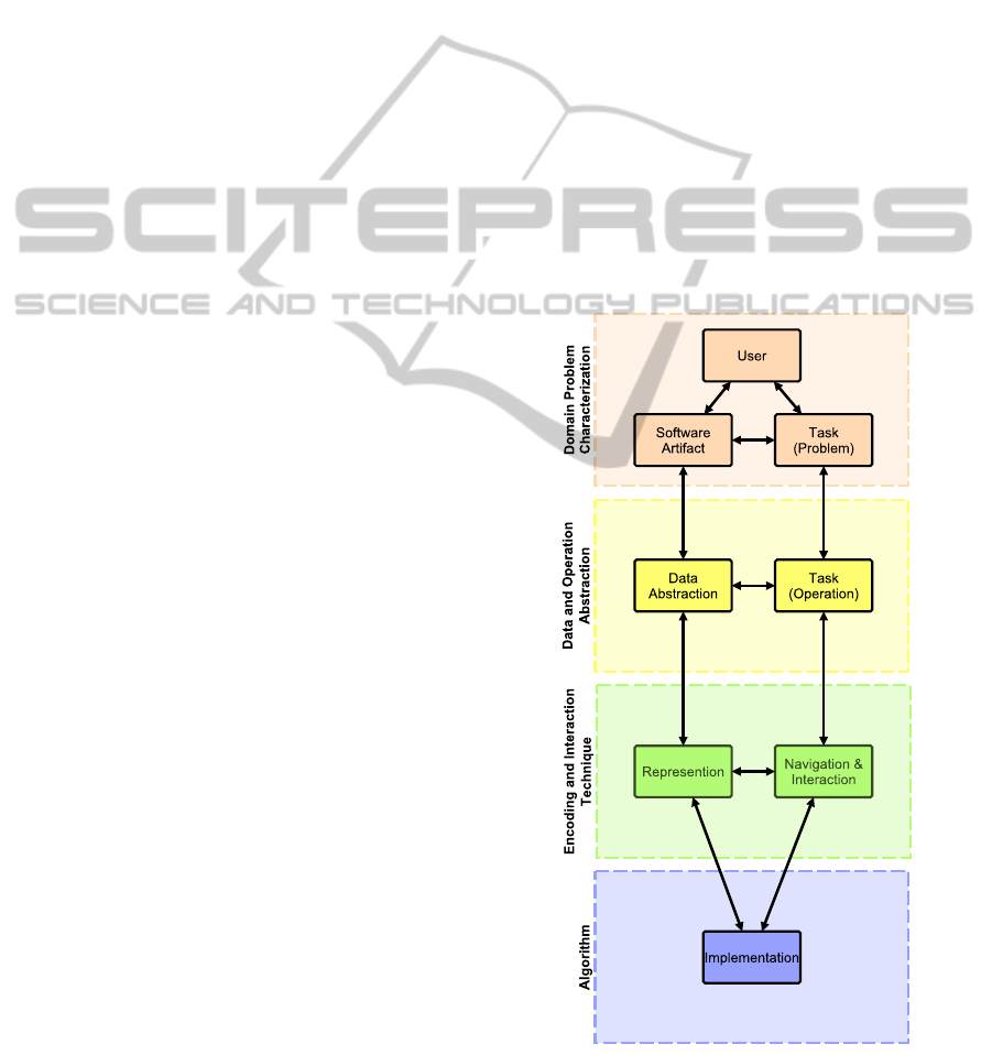
Figure 1: Domain specific adaption of Munzner’s extended
model for software visualization (Munzner, 2009; Meyer
et al., 2012).
AStructuredApproachforConductingaSeriesofControlledExperimentsinSoftwareVisualization
205

3 A NEW PERSPECTIVE ON
CONTROLLED EXPERIMENTS
In our approach, we adapt Munzner’s extended model
for visualization design and validation to the software
visualization domain (Munzner, 2009; Meyer et al.,
2012).
First, we derived the influence factors from sev-
eral taxonomies in the field of information visualiza-
tion in general and in the field of software visualiza-
tion in particular (Myers, 1990; Stasko and Patter-
son, 1993; Price et al., 1993; Roman and Cox, 1993;
Maletic et al., 2002; Storey et al., 2005; Gallagher
et al., 2008). These factors are user, task, software ar-
tifact, navigation and interaction, representation, and
implementation.
Then, we assigned these factors to Munzner’s ex-
tended model. Consequently, user, problem tasks,
and software artifact characterize the domain prob-
lem. Data abstractions and operation tasks are in the
data and operation abstraction layer. Representation
as well as navigation and interaction belong to the en-
coding and interaction technique layer. Finally, im-
plementation corresponds to the algorithm layer. The
resulting model is depicted in Figure 1.
These two steps provide an overview of the main
factors. In order to understand their relations they
have to be detailed and linked. This is supported by
the nested structure of the model and by the blocks
and guidelines. Table 1 details the factors from Fig-
ure 1 with possible instantiations where each factor is
marked with the color from the corresponding layer.
This list does not claim to be complete. Rather, it
is open for extension by other researchers conducting
controlled experiments in the field of software visual-
ization.
In a problem-driven approach the experimenter
has to define the scope of the domain. In software
visualization, a user has a specific role, a certain back-
ground, previous knowledge, and circumstances. The
user solves a problem task with a software artifact
where the artifact has a type and a size, and rep-
resents a specific aspect of a software system. To
abstract from the domain, the necessary information
from the software artifact is extracted into a suitable
data abstraction (implementation). The problem task
is divided into several operation tasks. On the next
layer, the data is represented using a certain tech-
nique in a certain dimension. The operation tasks are
processed with navigation and interaction techniques
supported by input and output devices. The final layer
contains the implementation. The representation and
interaction techniques have to be implemented with
an algorithm on a platform processing the data from
the software artifact. The visualization process might
be full-, semi-, or not automated at all.
4 PLANNING A SERIES OF
CONTROLLED EXPERIMENTS
We plan to conduct a series of experiments inves-
tigating the influence of dimensionality. Thus, our
research aims at the encoding and interaction tech-
nique layer. In the model, dimensionality is a sub-
factor of representation and might be influenced by
several other factors. Apart from group matching and
randomization, these factors are purposely either var-
ied, kept constant, or measured (Siegmund, 2012). To
vary the factor, it turns into an independent variable,
whose value is intentionally changed. To reduce or
at least to minimize the influence of the other fac-
tors, they are transformed into controlled variables
and have to be kept constant. The remaining factors
being difficult or not possible to control are measured
to analyze their influence on the result.
As an example, imagine a controlled experiment
with the following research question: Does an inher-
ent 3D software visualization reduce time to solve
software engineering tasks, compared to a 2D soft-
ware visualization? In the derived hypothesis time is
the dependent variable and dimensionality the inde-
pendent one. We apply a between-subjects design.
That means, there are a control group (2D) and an
experimental group (3D) where every participant is
member of only one group. In order to isolate dimen-
sionality as a factor under study we have to keep the
other factors constant or at least quasi-constant. The
participants act in the role of a developer and solve
two typical problem tasks, such as finding a bug or
identifying a dominating class. The tasks are detailed
with corresponding operation tasks. The visualiza-
tions are automatically generated from source code
of a medium-sized software artifact representing its
structure. The 2D and the inherent 3D visualization
have to be as similar as possible only differing in di-
mensionality. A suitable representation is a graph re-
spectively a nested node-link technique with corre-
sponding layout algorithms and shapes for 2D (e.g.,
rectangle) and 3D (e.g., cuboid). To solve their tasks,
the participants should gain an overview, zoom in and
out, filter, and identify relations in the visualization.
To overcome the interaction barrier between 2D and
3D input devices, both visualizations are controlled
with a touch device. Thus, the difference between 2D
input devices (e. g., keyboard and mouse) compared
to 3D ones (e. g., flystick) is eliminated. To minimize
the differences concerning the environment with re-
IVAPP2014-InternationalConferenceonInformationVisualizationTheoryandApplications
206
Table 1: Possible influence factors on the effectiveness of a software visualization.
Factor/Sub-Factor Examples for possible instantiations
User
Role Manager, Requirements Engineer, Architect, Developer, Tester, Maintainer, Reengi-
neer, Documenter, Consultant, Team, Researcher (Storey et al., 2005)
Background Age, Gender, Color Blindness, Ability of Stereoscopic Viewing
Knowledge Education, Programming Experience, Domain Knowledge
Circumstances Occupation, Familiarity with Study Object/Tools (Siegmund, 2012)
Task
Problem Development, Maintenance, Re-Engineering, Reverse Engineering, Software Process
Management, Marketing, Test, Documentation (Maletic et al., 2002)
Operation Retrieve Value, Filter, Compute Derived Value, Find Extremum, Sort, Determine
Range, Characterize Distribution, Find Anomalies, Cluster, Correlate (Amar et al.,
2005)
Software Artifact
Type Requirements, Architecture, Source Code, Stack Trace, Revision History
Size Small, Medium, Large (Wettel et al., 2011)
Aspect Structure, Behavior, Evolution (Diehl, 2007)
Representation
Dimensionality 2D, 2.5D, Augmented 2D, Adapted 2D, Inherent 3D (Stasko and Wehrli, 1993)
Technique Graph, Tree, Abstract/Real World Metaphor, Decorational/Representational Anima-
tion (Gra
ˇ
canin et al., 2005; Diehl, 2007; H
¨
offler and Leutner, 2007)
Navigation &
Interaction
Technique Overview, Zoom, Filter, Details-on-Demand, Relate, History, Extract (Shneiderman,
1996; Lee et al., 2006; Keim and Schneidewind, 2007; Yi et al., 2007)
Input Keyboard, Mouse, Gamepad, Flystick, Kinect, Touch Device, Leap Motion, Brain-
Computer Interface
Output Paper, Monitor, Projector, Virtual Reality Environment, Oculus Rift
Implementation
Algorithm Radial Layout, Balloon Layout, Treemap, Information Cube, Cone Tree (Herman et al.,
2000)
Platform
Dependence Platform Independent, Platform Dependent
Automation Full, Semi, Manual
Data Abstraction Famix, Dynamix, Hismo (Nierstrasz et al., 2005; Greevy, 2007; Ducasse et al., 2004)
gard to the output all participants solve their tasks in
the same virtual reality environment under equal con-
ditions. Therefore, they wear special 3D glasses to
receive the immersive view of the 3D visualization.
The participants using the 2D visualization also wear
them to eliminate influences due to, e. g., brightness
differences. Finally, the remaining factors that are
difficult or not to control have to be measured. The
participants are tested concerning color vision defi-
ciency and stereoscopic view ability to control their
effect on the participant’s performance. With respect
to the statistical analysis additional data about edu-
cation, programming experience, and domain knowl-
edge, i. e. virtual reality, touch devices, and 3D, are
collected.
With our structured approach making the influ-
ence factors and their relationships explicit, we are
able to vary different factors in different experiments
while keeping other relevant factors constant or mea-
sure their influence on the result. For example, we
keep the whole setting as described above and we
vary the representation technique, e. g., with another
metaphor using the additional dimension to integrate
structural and behavioral information or to represent
quality metrics, we change the size of the software ar-
tifact, or we use different tasks. Furthermore, we are
supported in documenting the experimental design, in
analyzing the threats to validity and in comparing our
results with other researchers.
AStructuredApproachforConductingaSeriesofControlledExperimentsinSoftwareVisualization
207

5 CONCLUSIONS AND FUTURE
WORK
In this paper we have presented our structured ap-
proach for conducting a series of controlled exper-
iments in software visualization. We derived im-
portant influence factors from information and soft-
ware visualization literature and assigned them to
Munzner’s extended model for visualization design
and validation. The domain specific adaption to soft-
ware visualization helps to relate and to control the
influence factors.
With this new perspective on controlled experi-
ments in software visualization, we are able to con-
duct a series of experiments obtaining comprehensive
empirical evidence of the advantages and disadvan-
tages of 3D.
REFERENCES
Amar, R., Eagan, J., and Stasko, J. (2005). Low-level com-
ponents of analytic activity in information visualiza-
tion. In Pro. 2005 IEEE Symp. Inf. Vis., page 15. IEEE
Computer Society.
Andrews, K. (2008). Evaluation comes in many guises. In
Proc. 2008 AVI Work. BEyond Time Errors Nov. Eval.
Method. Inf. Vis., pages 8–10.
Balogh, G. and Beszedes, A. (2013). CodeMetropolis – a
Minecraft based collaboration tool for developers. In
Proc. 1st IEEE Work. Conf. Softw. Vis., pages 1–4.
Basili, V. R., Selby, R. W., and Hutchens, D. H. (1986). Ex-
perimentation in software engineering. IEEE Trans.
Softw. Eng., 12(7):733–743.
Benomar, O. and Poulin, P. (2013). Visualizing Software
Dynamicities with Heat Maps. In 1st IEEE Work.
Conf. Softw. Vis. IEEE.
Bull, R. I., Storey, M.-A., Favre, J.-M., and Litoiu, M.
(2006). An Architecture to Support Model Driven
Software Visualization. In 14th Int. Conf. Progr.
Compr., pages 100–106. IEEE Computer Society.
Carpendale, S. (2008). Evaluating information visualiza-
tions. In Kerren, A., Stasko, J. T., Fekete, J.-D., and
North, C., editors, Information Visualization, volume
4950, pages 19–45. Springer, Berlin, Heidelberg.
Cockburn, A. and McKenzie, B. (2001). 3D or not 3D?:
evaluating the effect of the third dimension in a doc-
ument management system. In Proc. SIGCHI Conf.
Hum. factors Comput. Syst., pages 434–441. ACM.
Cockburn, A. and McKenzie, B. (2002). Evaluating the ef-
fectiveness of spatial memory in 2D and 3D physi-
cal and virtual environments. In Proc. SIGCHI Conf.
Hum. Factors Comput. Syst., pages 203–210. ACM.
Di Penta, M., Stirewalt, R. E. K., and Kraemer, E. (2007).
Designing your Next Empirical Study on Program
Comprehension. 15th Int. Conf. Progr. Compr., pages
281–285.
Diehl, S. (2007). Software visualization: Visualizing
the Structure, Behaviour, and Evolution of Software.
Springer.
Ducasse, S., G
ˇ
ırba, T., and Favre, J. (2004). Modeling soft-
ware evolution by treating history as a first class en-
tity. In Proc. Work. Softw. Evol. Through Transform.,
pages 75–86. Elsevier.
Dwyer, T. (2001). Three dimensional UML using force di-
rected layout. In Proc. 2001 Asia-Pacific Symp. Inf.
Vis., volume 9, pages 77–85. Australian Computer So-
ciety.
Fittkau, F., Waller, J., Wulf, C., and Hasselbring, W. (2013).
Live Trace Visualization for Comprehending Large
Software Landscapes : The ExplorViz Approach. In
1st IEEE Work. Conf. Softw. Vis., pages 1–4.
Gallagher, K., Hatch, A., and Munro, M. (2008). Software
Architecture Visualization: An Evaluation Frame-
work and Its Application. IEEE Trans. Softw. Eng.,
34(2):260–270.
Gra
ˇ
canin, D., Matkovi
´
c, K., and Eltoweissy, M. (2005).
Software Visualization. Innov. Syst. Softw. Eng.,
1(2):59–63.
Greevy, O. (2007). Dynamix - a meta-model to support
feature-centric analysis. In 1st Int. Work. FAMIX
Moose Reeng.
Herman, I., Melancon, G., and Marshall, M. S. (2000).
Graph visualization and navigation in information vi-
sualization: A survey. IEEE Trans. Vis. Comput.
Graph., 6(1):24–43.
H
¨
offler, T. N. and Leutner, D. (2007). Instructional anima-
tion versus static pictures: A meta-analysis. Learn.
Instr., 17(6):722–738.
Huynh-Thu, Q., Barkowsky, M., and Le Callet, P. (2011).
The Importance of Visual Attention in Improving the
3D-TV Viewing Experience: Overview and New Per-
spectives. IEEE Trans. Broadcast., 57(2):421–431.
Irani, P. and Ware, C. (2000). Diagrams based on struc-
tural object perception. In Proc. Work. Conf. Adv. Vis.
Interf., pages 61–67. ACM.
Irani, P. and Ware, C. (2003). Diagramming information
structures using 3D perceptual primitives. ACM Trans.
Comput. Hum. Interact., 10(1):1–19.
Isenberg, T., Isenberg, P., Chen, J., Sedlmair, M., and
M
¨
oller, T. (2013). A systematic review on the practice
of evaluating visualization. IEEE Trans. Vis. Comput.
Graph., 19(12):2818–27.
Keim, D. A., Kohlhammer, J., Ellis, G., and Mansmann, F.
(2010). Mastering The Information Age-Solving Prob-
lems with Visual Analytics. Eurographics Association.
Keim, D. A. and Schneidewind, J. (2007). Introduction to
the Special Issue on Visual Analytics. SIGKDD Ex-
plorations, 9(2):3–4.
Koike, H. and Chu, H. (1998). How does 3-D visualization
work in software engineering?: empirical study of a 3-
D version/module visualization system. In Proc. 20th
Int. Conf. Softw. Eng., pages 516–519. IEEE Com-
puter Society.
Kosara, R., Healey, C. G., Interrante, V., Laidlaw, D. H.,
and Ware, C. (2003). User Studies: Why, How, and
When? IEEE Comput. Graph. Appl., 23(4):20–25.
IVAPP2014-InternationalConferenceonInformationVisualizationTheoryandApplications
208

Lee, B., Sims Parr, C., Plaisant, C., and Bederson, B. B.
(2006). Visualizing Graphs as Trees: Plant a seed and
watch it grow. In 13th Int. Symp. Graph Draw., vol-
ume 3843, pages 516–518. Springer.
Levy, E., Zacks, J., Tversky, B., and Schiano, D. (1996).
Gratuitous graphics? Putting preferences in perspec-
tive. In Proc. SIGCHI Conf. Hum. Factors Comput.
Syst., pages 42–49. ACM.
Maletic, J., Marcus, A., and Collard, M. (2002). A task ori-
ented view of software visualization. In 1st Int. Work.
Vis. Softw. Underst. Anal., pages 32–40. IEEE Com-
pututer Society.
Meyer, M., Sedlmair, M., and Munzner, T. (2012). The
four-level nested model revisited: blocks and guide-
lines. In Proc. 2012 Work. BEyond Time Errors Nov.
Eval. Method. Vis., pages 1–6.
M
¨
uller, R., Kovacs, P., Schilbach, J., and Eisenecker, U.
(2011). Generative Software Visualizaion: Automatic
Generation of User-Specific Visualisations. In Proc.
Int. Work. Digit. Eng., pages 45–49.
Munzner, T. (2009). A nested model for visualization de-
sign and validation. IEEE Trans. Vis. Comput. Graph.,
15(6):921–928.
Myers, B. A. (1990). Taxonomies of visual programming
and program visualization. J. Vis. Lang. Comput.,
1(1):97–123.
Nierstrasz, O., Ducasse, S., and G
ˇ
ırba, T. (2005). The story
of moose: an agile reengineering environment. In
Proc. 10th Eur. Softw. Eng. Conf., pages 1–10. ACM.
Pfleeger, S. L. (1995). Experimental design and analysis in
software engineering. Ann. Softw. Eng., 1(1):219–253.
Price, B. A., Baecker, R. M., and Small, I. S. (1993). A Prin-
cipled Taxonomy of Software Visualization. J. Vis.
Lang. Comput., 4(3):211–266.
Roman, G.-C. and Cox, K. C. (1993). A taxonomy of pro-
gram visualization systems. Computer, 26(12):11–24.
Sensalire, M., Ogao, P., and Telea, A. (2009). Evaluation of
software visualization tools: Lessons learned. In 5th
Int. Work. Vis. Softw. Underst. Anal., pages 19–26.
Sharif, B. and Jetty, G. (2013). An Empirical Study Assess-
ing the Effect of SeeIT 3D on Comprehension. In 1st
IEEE Work. Conf. Softw. Vis.
Shneiderman, B. (1996). The eyes have it: A task by
data type taxonomy for information visualizations. In
Proc. 1996 IEEE Symp. Vis. Lang., pages 336–343.
Siegmund, J. (2012). Framework for Measuring Pro-
gram Comprehension. Phd thesis, Otto-von-Guericke-
Universit
¨
at Magdeburg.
Sjoberg, D. I. K., Dyb
˚
a, T., and Jorgensen, M. (2007). The
Future of Empirical Methods in Software Engineering
Research. In Futur. Softw. Eng. (FOSE ’07), pages
358–378.
Smisek, J., Jancosek, M., and Pajdla, T. (2011). 3D with
Kinect. In 2011 IEEE Int. Conf. Comput. Vis. Work.,
pages 1154–1160.
Stasko, J. and Patterson, C. (1993). Understanding and
Characterizing Program Visualization Systems. Tech-
nical report, Georgia Institute of Technology, Atlanta.
Stasko, J. and Wehrli, J. (1993). Three-dimensional com-
putation visualization. Proc. 1993 IEEE Symp. Vis.
Lang., pages 100–107.
Storey, M.-A. D.,
ˇ
Cubrani
´
c, D., and German, D. M. (2005).
On the use of visualization to support awareness of
human activities in software development: a survey
and a framework. In Proc. 2005 ACM Symp. Softw.
Vis., pages 193–202. ACM.
Teyseyre, A. R. and Campo, M. R. (2009). An overview of
3D software visualization. IEEE Trans. Vis. Comput.
Graph., 15(1):87–105.
Tichy, W. and Padberg, F. (2007). Empirische Methodik
in der Softwaretechnik im Allgemeinen und bei der
Software-Visualisierung im Besonderen. In Softw.
Eng. 2007 Beitr. Work., pages 211–222. Gesellschaft
f
¨
ur Informatik.
Waller, J., Wulf, C., Fittkau, F., D
¨
ohring, P., and Hassel-
bring, W. (2013). SynchroVis: 3D Visualization of
Monitoring Traces in the City Metaphor for Analyz-
ing Concurrency. In 1st IEEE Work. Conf. Softw. Vis.,
pages 7–10.
Ware, C. and Franck, G. (1994). Viewing a graph in a virtual
reality display is three times as good as a 2D diagram.
IEEE Symp. Vis. Lang., pages 182–183.
Ware, C. and Franck, G. (1996). Evaluating stereo and mo-
tion cues for visualizing information nets in three di-
mensions. ACM Trans. Graph., 15(2):121–140.
Ware, C., Hui, D., and Franck, G. (1993). Visualizing object
oriented software in three dimensions. In Proc. 1993
Conf. Cent. Adv. Stud. Collab. Res. Softw. Eng., pages
612–620. IBM Press.
Ware, C. and Mitchell, P. (2008). Visualizing graphs in
three dimensions. ACM Trans. Appl. Percept., 5(1):1–
15.
Weichert, F., Bachmann, D., Rudak, B., and Fisseler, D.
(2013). Analysis of the accuracy and robustness of
the leap motion controller. Sensors, 13:6380–6393.
Wettel, R., Lanza, M., and Robbes, R. (2011). Software
systems as cities: A controlled experiment. In Proc.
33rd Int. Conf. Softw. Eng., pages 551–560. ACM.
Wohlin, C., Runeson, P., H
¨
ost, M., Ohlsson, M. C., Reg-
nell, B., and Wessl
´
en, A. (2012). Experimentation in
Software Engineering. Springer.
Yi, J. S., ah Kang, Y., Stasko, J. T., and Jacko, J. A. (2007).
Toward a deeper understanding of the role of inter-
action in information visualization. IEEE Trans. Vis.
Comput. Graph., 13(6):1224–1231.
Zorrilla, M., Martin, A., Sanchez, J. R., Tamayo, I., and
Olaizola, I. G. (2013). HTML5-based system for in-
teroperable 3D digital home applications. Multimed.
Tools Appl., pages 1–21.
AStructuredApproachforConductingaSeriesofControlledExperimentsinSoftwareVisualization
209
