
Architectural Design of a Deployment Platform to Provision
Mixed-tenancy SaaS-Applications
Matthias Reinhardt
1
, Stefan T. Ruehl
2
, Stephan A. W. Verclas
3
, Urs Andelfinger
1
and Alois Sch
¨
utte
1
1
University of Applied Sciences Darmstadt, Haardtring 100, 64295 Darmstadt, Germany
2
Clausthal University of Technology, Albrecht-von-Groddeck-Str. 7, 38678 Clausthal-Zellerfeld, Germany
3
T-Systems International GmbH, Heinrich-Hertz-Str. 1, 64295 Darmstadt, Germany
Keywords:
Software Architecture, Software Design, Web and Internet Services.
Abstract:
Software-as-a-Service (SaaS) is a delivery model whose basic idea is to provide applications to the customer on
demand over the Internet. In contrast to similar but older approaches, SaaS promotes multi-tenancy as a tool to
exploit economies of scale. This means that a single application instance serves multiple customers. However,
a major throwback of SaaS is the customers’ hesitation of sharing infrastructure, application code, or data with
other tenants. This is due to the fact that one of the major threats of multi-tenancy is information disclosure
due to a system malfunction, system error, or aggressive actions by individual users. So far the only approach
in research to counteract on this hesitation has been to enhance the isolation between tenants using the same
instance. Our approach (presented in earlier work) tackles this hesitation differently. It allows customers to
choose if or even with whom they want to share the application. The approach enables the customer to make
that choice not just for the entire application but specifically for individual application components and the
underlying infrastructure. This paper contributes to the mixed-tenancy approach by introducing a software
pattern that allows to establish communication between Application Components that are deployed following
the mixed-tenancy paradigm. The contributions of this paper are evaluated based on a representative example
that employs all possible kinds of communication.
1 INTRODUCTION
Software-as-a-Service (SaaS) is a delivery model
whose basic idea is to provide applications to the cus-
tomer on demand over the Internet. SaaS promotes
multi-tenancy (MT) as a tool to exploit economies of
scale. This means that a single application instance
serves multiple customers. However, even though
multiple customers use the same instance, each of
them has the impression that the instance is desig-
nated only to themselves. This is achieved by iso-
lating the tenants’ data from each other (Chong and
Carraro, 2006).
In contrast to single-tenancy, MT has the advan-
tage that IT-Infrastructure may be used most effi-
ciently as it is possible to host as many tenants as
possible on the same instance. Thus, operational
and maintenance cost of the application is decreased.
However, one of the major threats of MT applications
is information disclosure due to data breach (Bezemer
and Zaidman, 2010; Cloud Security Alliance, 2013).
This may occur through a system error, malfunction,
or destructive action. So far this problem has only
been tackled by proposing new approaches to imple-
ment and improve the tenant isolation on a single in-
stance.
The approach presented in (Ruehl et al., 2012; Ruehl
et al., 2013), however, is different as it strives to
solve the problem by finding a hybrid solution be-
tween multi-tenancy and single-tenancy. We refer to
this approach as mixed-tenancy. The approach tries to
emphasize both the customers’ concerns about shar-
ing infrastructure as well as the operator’s desire to
utilize infrastructure as efficiently as possible.
The approach that is supposed to answer these
questions starts by building an MT application
based on the concept of Service-oriented Architecture
(SOA). This means the so-called composite SaaS-
applications are composed of a number of application
components (AC) that each offer atomic functional-
ity. The approach enables the customer to choose if
or even with whom they want to share a specific AC
395
Reinhardt M., Ruehl S., Verclas S., Andelfinger U. and Schütte A..
Architectural Design of a Deployment Platform to Provision Mixed-tenancy SaaS-Applications.
DOI: 10.5220/0004813803950402
In Proceedings of the 4th International Conference on Cloud Computing and Services Science (CLOSER-2014), pages 395-402
ISBN: 978-989-758-019-2
Copyright
c
2014 SCITEPRESS (Science and Technology Publications, Lda.)
Toward a Method for realization of customizable multi-tenancy Applications
Architectural Idea for the Variability Problem
2
Tenants
Execution Engine
<<uses>>
Application
Components
1
2
3
Dispatcher
1
2
3
4
5
6
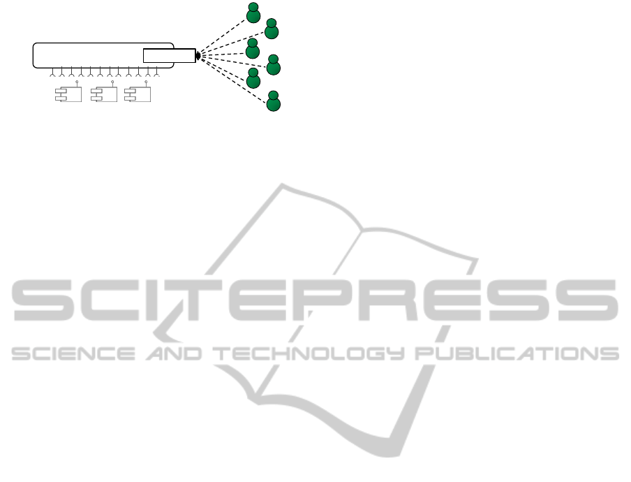
Figure 1: Architectural overview.
and the underlying infrastructure stack. This way cus-
tomers may declare their requirements toward a de-
ployment of their application variant.
As an example please refer to Figure 1. It illustrates
a setting in which six tenants are using an application
that is composed of three ACs. Example requirements
that would be possible are:
1. AC 1 is not handling any critical data, thus all ten-
ants feel comfortable to share instances and the
underlying Virtual Machines.
2. AC 2, however, handles semi-sensitive data.
Thus, tenant 2, for example, only wants to share
an instance with European companies but not with
competitors. However, on a Virtual Machine
(VM) level, tenant 2 agrees to share with all cus-
tomers that are not competitors.
3. AC 3 is handling very sensitive data. Thus, ten-
ants will require quite restrictive deployments.
Tenant 4, for example, stated that they do not wish
to share an instance with competitors and only
with companies from the USA.
4. Tenant 6 is special in the sense that they demand
a single instance for their private use of every AC
and VM.
In (Ruehl et al., 2013) a semantic model is presented
that allows customers to describe their constraints
towards a mixed-tenancy deployment. Based on
this model the Deployment Configuration Generator
(DCG) may be used to capture customer constraints.
Furthermore, once the constraints were added into the
DCG, a deployment is calculated that applies to all
expressed customer constraints and is optimal accord-
ing to resource consumption. This deployment is de-
scribed in a transfer document that we refer to as de-
ployment configuration (DC). This will be discussed
in detail by Section 3. Based on the DC, a given
multi-tenancy enabled composite application may be
deployed according to the mixed-tenancy paradigm.
This paper’s contribution is a software pattern that
may be applied to establish communication between
ACs deployed in a mixed-tenancy environment. The
pattern shall be able to solve the special challenges
that appear in such an environment. First of all, this
pattern shall be able to enforce the customer given
constraints for the data communication between com-
ponents. And secondly, the pattern promotes the pos-
sibility to migrate existing multi-tenancy applications
into a mixed-tenancy environment without having to
change the application.
In order to do that the paper is structured as fol-
lows. After a discussion of related work, the paper
will start with an analysis of requirements that archi-
tecture of the mixed-tenancy platform has to meet.
The paper continues by developing the pattern to es-
tablish communication. This is done by first dis-
cussing existing patterns with respect to the defined
requirements, and combine those to satisfy the re-
quirements. In order to be capable of evaluating the
communication pattern, it is necessary to develop a
mechanism that can automatically deploy an applica-
tion according to a DC. This is presented by Section 5.
Section 6 will conduct an evaluation of the presented
pattern by analyzing specifically built scenarios that
represent a wide variety of possible cases.
The paper concludes with summarizing the results
and drawing a conclusion.
2 RELATED WORK
SaaS in general as well as the configuration issues
and challenges related to it were explored in (Sun
et al., 2008). The aspect of functional variability has
been discussed in some work. As, for example, in
(Mietzner et al., 2009) the author discusses bringing
such flexibility to the process layer of process-based,
service-oriented SaaS-applications. This is done by
creating variability descriptors that are transformed
into a BPEL process model. In (Lizhen et al., 2010)
an approach is presented to describe variability for
SaaS-applications. This approach can systematically
describe variability points and their relationships, and
it assures the quality of the configuration inputs made
by the customers. This work focuses on the creation
of descriptions of functional variability. Furthermore,
there are approaches with the goal to realize MT
that meets privacy and performance requirements. In
(Guo et al., 2007), for example, a framework for
multi-tenant aware SaaS-applications including data
isolation, performance isolation or configuration is
described. Our approach, in contrast, allows the cus-
tomer to give input for how and with whom their ACs
are deployed. Data security is achieved as tenants do
not share the same AC instances. To the best of our
knowledge there is no similar approach. In addition,
approaches that realize tenants’ isolation on an MT
instance may be applied.
CLOSER2014-4thInternationalConferenceonCloudComputingandServicesScience
396

3 REQUIREMENTS ANALYSIS
This section’s purpose is to discuss the necessary re-
quirements towards realizing a mixed-tenancy plat-
form. The platform consists of two major tasks. The
first is the automatic deployment, whose job is to de-
ploy the application according to the description of
the DC. A prototypical implementation of the deploy-
ment task will be discussed in section 5. This may re-
quire that multiple VMs need to be created and ACs,
that make up the application, will be instantiated mul-
tiple times. The DC is the output of the aforemen-
tioned DCG and describes the deployment that is to be
realized. Thus, the DC defines how many instances of
a specific component shall be instantiated on a partic-
ular server and which tenants are allowed to access
them. It captures a deployment that applies to all
constraints of all tenants using the application. Ad-
ditionally, the DC was created to be optimal accord-
ing to resource consumptions in order to satisfy the
service providers’ need for efficient use of infrastruc-
ture. Figure 2 illustrates the structure of the DC in
Entity-Relationship Notation. The figure captures the
relationship between the important entities (Servers,
ACs, ACIs, Tenants and Users). These entities have
been included in an XML-schema, from which a valid
DC can be created by defining an XML-file which
refers to the schema. This allows us to decouple the
DCG from the rest of the platform.
The second important task of the platform is the
communication. This task of the platform is in charge
of establishing communication between the deployed
component instances. Since it is our aim to keep
the adaptation progress of an application at a mini-
mum, one requirement of the communication task is
the separation of the application logic and the plat-
form logic. This may be realized by introducing a new
layer above the original application logic. This plat-
form logic layer manages the communication. Fur-
thermore, it is important, that the platform’s commu-
nication applies to the customers’ wishes. If a tenant
denies the common deployment with another tenant,
the platform has to make sure that this can happen
under no circumstances. Hence, it has to be avoided,
that the data communication of two tenants, who may
are competitors, is redirected through a common point
of intersection. This is the second requirement that
needs to be fulfilled by the communication pattern. It
is based on the respect for the customers’ wishes. If a
customer denies to share a component with his com-
petitor, it is not legitimate to redirect both their data
traffic through a global interstation. Another reason
is a possible high amount of data traffic which could
slow down the running application.
Server Tenan t
AC
ACI 1 2
3
1 n
1 n
1
n
cpu ram
id id
id
1: offers / is deployed on
2: belongs to / uses
3: is instance of / is instantiated by
4: employs / belongs to
User
4
n
1
pass
ip
name
Figure 2: Structure of Deployment Configuration (ERM).
4 PATTERN SELECTION
The main goal of this paper is to develop a proper de-
sign pattern that allows to establish communication
by realizing the prerequisites, that were introduced in
the last chapter. To achieve this, we investigate well-
established design patterns as well as intuitive ap-
proaches. We chose a simple example of a DC which
contains a special case. In the following, the exam-
ple will be applied to every pattern. This allows to
illustrate how the platform would behave in common
situations as well as in the special case. Additionally,
it will be possible to compare the individual results
in order to select the most appropriate pattern. The
comparison is shown in Figure 3 via visualizations of
the structure and the sequence (UML sequence dia-
grams).
The example consists of two tenants who are using
an application with three components. There are five
application component instances (ACI) where their
border color indicates the tenant belonging. The reg-
ular case is demonstrated at component 1 and 3 where
both tenants use exclusively one instance. As to com-
ponent 2 there is only one instance which is shared be-
tween tenant 1 and 2. As discussed in the last section
it is important that the platform maintains decentral-
ized communication and separation of the platform
logic in both cases. Another element which exists
in all diagrams is the Execution Engine (EE). It be-
longs to the platform and has the knowledge of all
component-instance locations and tenant belongings.
It may fulfill additional tasks depending on the spe-
cific patterns it is used in.
The first pattern we came up with we called del-
egator. Within this pattern the EE’s job is to dele-
gate communication. When a user or a component
instance wants to use a service of another component
it asks the delegator which instance of that component
belongs to the current tenant. This control communi-
cation is represented by the dashed arrows in Figure
3. The EE responds with the whereabouts in form of
ArchitecturalDesignofaDeploymentPlatformtoProvisionMixed-tenancySaaS-Applications
397
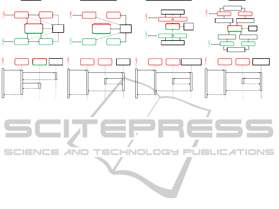
ACI 1.1
ACI 2.1
ACI 3.1
ACI 1.2 ACI 3.2
EE
Ten ant 1
Ten ant 2
Delegator
ACI 1.1
ACI 2.1
ACI 3.1
ACI 1.2 ACI 3.2
EE
Ten ant 1
Ten ant 2
Mediator (global)
ACI 1.1
ACI 2.1
ACI 3.1
ACI 1.2 ACI 3.2
EE
Mediator 1
Mediator 2
Ten ant 1
Ten ant 2
Mediator (per Tenant) Adapter
ACI 1.1
ACI 2.1 EE
Ten ant 1
doSomething()
doSomething()
getInstance(ac2)
address
response
response
ACI 1.1
ACI 3.1 Mediator 1
Ten ant 1
doSomething()
doSomething()
ac3_doSomething()
response
response
response
ACI 3.1
ACI 1.1 EE
Ten ant 1
doSomething()
doSomething()
ac1_doSomething()
response
response
response
ACI 1.1
ACI 3.1 Adapter 1
Ten ant 1
doSomething()
doSomething()
ac3_doSomething()
response
response
response
Adapter 5
Adapter 4
ACI 1.1
ACI 2.1
ACI 3.1
ACI 1.2 ACI 3.2
EE
Adapter 2 Adapter 3
Adapter 1
Adapter 6
Ten ant 1
Ten ant 2
Figure 3: Overview of different Patterns to tackle the Communication Challenge.
an address. Thereby a contact can be established be-
tween the two instances or the user and the instance.
This direct communication is represented by the solid
lines. Changes of the locations are no issue, because
the contact to the EE will happen before every func-
tion call of another component instance.
With respect to the requirements, there is a prob-
lem with the separation of the platform logic. The sin-
gle instance of component 2 knows multiple instances
of a component because it is shared by multiple ten-
ants. Thus, we need platform logic in the component,
which is not desired because it complicates the adap-
tation process of an application to the platform. How-
ever, the pattern meets the requirement for decentral-
ized communication that applies to customers’ con-
straints.
Secondly, we engaged in with the mediator pat-
tern provided by Gamma et al. (Gamma et al., 1994).
The Mediator is an object which encapsulates the in-
teraction between an amount of objects. Thus, the
objects are able to communicate without directly con-
necting to each other. Through our investigation
two ways to implement the pattern into the platform
emerged – global and concrete mediator.
The global mediator is characterized by a sin-
gle mediator object which is represented by the EE.
There are solid lines in Figure 3 between the com-
ponent instances and the mediator. This means that
all data communication between the component in-
stances passes through the global mediator, unlike the
delegator pattern where the data communication hap-
pens directly between the component instances.
With the use of the global mediator, there is no
communication logic inside the components. They
just have to be able to communicate with the EE.
Thus, there is no problem with the special case of
component 2, where one instance is used by two
tenants at once. But because of the passing of the
complete data communication through the EE, we
detected a problem with the other requirement. If
the customer requested the separation to another cus-
tomer, it is not legitimate to redirect both their data
communication through a common point of intersec-
tion, which, unfortunately, is the case here. Another
negative aspect is a possible overload of the global
mediator in a larger scenario, which could slow down
the system as the global mediator becomes a bottle-
neck for all communication.
Another way to adapt the mediator pattern is
shown by Figure 3 by the use of multiple mediator
objects, one mediator per tenant. In contrast to the
global mediator the data communication which passes
a mediator is related to the same tenant. Because of
this, we have successfully respected the requirement
of decentralized communication.
In case of component 2 there exists only one in-
stance used by both tenants. The instance has to de-
cide which mediator to contact if it wants to call a
function of another component. Clearly, there is com-
munication logic necessary inside the components
which stands in conflict with the second requirement.
Another pattern we ported onto the platform is the
adapter pattern which was also given by Gamma et
al. (Gamma et al., 1994). Usually, it will be applied
to establish communication despite incompatible in-
terfaces. For example, when third-party components
should be included into a software without the possi-
bility to adjust the interfaces, an adapter is an appro-
priate solution. In figure 3 there exists an adapter be-
tween every two component instances that will even-
tually need to communicate. Such adapters encapsu-
late the functionality of their related component in-
stances.
In this setup we follow the requirement of de-
CLOSER2014-4thInternationalConferenceonCloudComputingandServicesScience
398
centralized communication. The data communication
passing an adapter is related to the same tenant. With
respect to the second requirement we have noticed a
violation in the case of component 2. A common used
component instance must decide which adapter to ad-
dress. This decision has to be made depending on the
current accessing tenant. Thus, communication logic
is necessary inside the components.
So far none of the investigated patterns have
matched both previously defined requirements. On
this account we created a new pattern resulting the
positive aspects of the previous patterns. It is called
Connector because of its behavior. It has no rela-
tion to other homonymous design patterns which can
be found in literature (e.g. Acceptor and Connector
(Schmidt, 1995)).
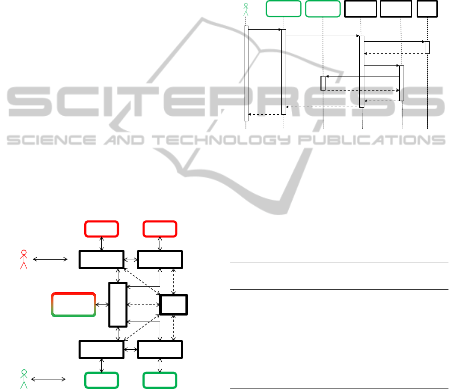
Figure 4 describes the structure of the pattern. For
every component instance there exists a related con-
nector element. The component instances are solely
able to initiate a connection to their connector. This
is geared to the global adapter pattern, where there
also was no platform logic located in the component
instances. In contrast to the global mediator, this ap-
proach is distributing the platform intelligence into
multiple connector elements and not into a single ob-
ject like a mediator. Besides, there is a direct commu-
nication between the connector-elements. This works
just like in the delegator pattern.
ACI 1.1
ACI 2.1
ACI 3.1
ACI 1.2 ACI 3.2
EE
Connector
1.1
Connector
3.1
Connector
2.1
Connector
1.2
Connector
3.2
Ten ant 1
Ten ant 2
Figure 4: Example of the connector pattern.
In Figure 5 it is demonstrated how the communi-
cation works. If a component instance respectively a
user wants to retrieve data from another component,
it is calling the specific function at the related con-
nector. Thus, here is no platform logic necessary. The
component instance treats the function just like a local
one. The connector is now handling the establishment
of the connection. The EE acts just like the delegator
element. The only difference is that the connector is
requesting the address or the reference of the corre-
sponding connector of the target component instance -
not of the component-instance. After the actual func-
tion call took place, the result will be returned to the
initial calling component instance. As illustrated by
Figure 5, a connector encapsulates the needed func-
tions of all other components for the related compo-
nent instance and the provided functions to be called
by the other component instances.
ACI 1.2
ACI 3.2
Connector
1.2
Tenant 2
doSomething()
doSomething()
ac3_doSomething()
return response
return response
return response
Connector
3.2
EE
getInstance(a)
return address
doSomething()
return response
Figure 5: Sequence diagram of the connector pattern.
The pattern fits the requirements. As already ex-
plained in the last section, we have achieved a de-
centralized communication and the separation of plat-
form logic. Because of this, we elect the connector
pattern to the best way for solving the discussed prob-
lem. A summary of the investigated patterns and their
ratings is shown in Table 1.
Table 1: Overview of the results of pattern analysis.
Pattern Decentralized
Communication
Separation of
Platform Logic
Delegator " %
Mediator
(global)
% "
Mediator
(per tenant)
" %
Adapter " %
Connector " "
5 PROTOTYPE REALIZATION
Since we were able to identify a mixed-tenancy archi-
tecture, there is the need to prove its functionality and
practicability. The intent of this section is the descrip-
tion of a case-study which has been realized using the
connector pattern. This provides a base for an eval-
uation of the architecture in the next section. This
ArchitecturalDesignofaDeploymentPlatformtoProvisionMixed-tenancySaaS-Applications
399

section addresses the requirements of the deployment
task which have been defined in Section 3.
The main focus of the project relied on how
to automatically deploy multiple instances of differ-
ent components, which afterwards shall communicate
with each other. In Figure 6 you can see the auto-
matic deployment of an exemplary mixed-tenancy ap-
plication. There is a basic VM that is in charge of the
deployment. At first the deployment of multiple tar-
get VMs starts, which is followed by the deployment
of application component instances (ACI) and the re-
lated connector elements. The locations and number
of deployments executed by the EE are given. They
result from the customers’ requirements.
…
Execution
Engine
VM
VM 1
VM 2
…
VM n
ACI
2.2
ACI
m.1
ACI
2.1
ACI
1.1
…
ACI
1.2
…
…
ACI
2.n
ACI
1.n
ACI
m.2
…
ACI
m.n
Figure 6: Deployment of application components.
The idea was to develop a mixed-tenancy plat-
form. This means, that it is possible to attach existing
multi-tenancy applications to the platform in order to
make it mixed-tenancy capable. Thus, we realized the
deployment task essentially using VMware vSphere
1
technolog and GlassFish
2
application servers. We
used the VMware Virtual Infrastructure Java API
(VI java)
3
, which is an open source project initi-
ated by VMware. The advantages against the official
VMware vSPhere Management SDK are its higher
performance and easier handling (Jin, 2013).
The ACs are encapsulated in web archives (WAR-
files) and located at the same VM as the EE. During
the execution process of a DC, these WAR-files will
be duplicated and modified before they will automati-
cally be uploaded and deployed on the target VM. To
deploy an ACI we used the GlassFish asadmin tool.
To allow or deny the access to an ACI we set the de-
ployment descriptor of the WAR-file according to the
information of the submitted DC. The modification of
each concrete ACI is necessary, because the deploy-
ment constructor consists of many entries that cannot
be identical if two ACIs should be deployed on the
same server. This way each ACI is unique and can be
1
http://www.vmware.com/de/products/vsphere/
2
https://glassfish.java.net/
3
http://vijava.sourceforge.net/
identified.
The restricted access of AC instances gains secu-
rity benefits over a pure multi-tenancy deployment.
This is due to the fact that access restrictions to dif-
ferent instances of the same AC increases tenants’ iso-
lation.
The communication between the connector ele-
ments is realized via REST interfaces. To transmit the
necessary number of VMs and ACIs we have defined
a specific XML schema. A document following this
schema contains a number of servers and instances of
each component of the application. Furthermore, for
each instance it is declared which tenants are allowed
to access it. The implementation of SSL encryption
would be a further step towards increasing tenants’
isolation. This will be tackled in future.
6 EVALUATION
Based on the realized prototype of a platform intro-
duced in the previous section, it is now possible to
evaluate the planned mixed-tenancy architecture. Ob-
viously, the platform is not runnable on its own, as
it is supposed to deploy and run a multi-tenancy ap-
plication. Because of this, we need to develop a
dummy multi-tenancy application and port it onto the
platform. We made sure, that the application com-
prises all possible special cases as well as the regu-
lar cases. This means that it is built op of multiple
components that interact with each other directly or
indirectly. An indirect interaction occurs whenever a
component instance or a tenant advises a second com-
ponent instance to call a function of a third component
instance. When it comes to the properties of mixed-
tenancy, we need to test a row of things.
In order to test the functionality of the developed
platform, we made sure that all possible forms of cus-
tomer constraints will be deployed without malfunc-
tions. At first we have to distinguish between the
server and the component layer. At both layers there
exist multiple isolation levels.
At first we describe the levels at the component
layer. Shared means that there is only one instance
of the component, which is used by multiple tenants
simultaneously. Separate on the contrary represents
single instances of the component owned by each ten-
ant. At last there is a level called mixed which com-
prises all remaining cases. At this level, there is at
least one component instance that is used by more
than one but not all existing tenants.
Regarding the server level, this is quite similar.
Shared means that all tenants share one server where
all component instances are deployed. At the separate
CLOSER2014-4thInternationalConferenceonCloudComputingandServicesScience
400

level each tenant needs a single server where all his
component instances are deployed. Mixed means that
at least two tenants are using component instances on
the same server.
After the identification and the classification of all
realistic cases, we combined the server and compo-
nent layer. Since each of the layers has three levels, it
is resulting in 9 permutations. Three of the 9 permu-
tations are not realistic, e.g. if two tenants share one
component instance, they cannot possess their own
servers. This finally leads to 6 possibilities.
All test cases that belong to the same of the 6 re-
sulting classes are equivalent. This means that we just
need to test one to prove its functionality. For exam-
ple, if we can successfully deploy a shared instance of
component A on a server, then this result represents
the operativeness of the shared deployment of com-
ponent B. Thus, we elected one test case for each of
the 6 classes. For each one we have tested direct and
indirect access of the deployed component instances
and verified the effect was as anticipated.
Due to the fact that all our test cases run through
with success, we can say that our realized mixed-
tenancy architecture which is embodied by the con-
nector pattern is a working solution for the discussed
problem. The evaluation has proven that our de-
fined prerequisites were successfully enforced for the
dummy application.
However, there are throwbacks coming from the
utilized pattern. First of all performance will be de-
creased. This is due to the communication behavior,
where ACs do not communicate directly with each
other anymore. Instead communication is handled by
connectors. This causes overhead. Secondly, if an op-
erator decides to host a multi-tenancy application fol-
lowing the mixed-tenancy approach, it is necessary to
create the connectors for all application components
involved. The effort necessary to do that could only
be minimized if it would be possible to automatically
generate connectors through code inspection.
7 SUMMARY AND CONCLUSION
In the first chapter we introduced this paper with the
characteristics of multi-tenancy as well as the advan-
tages and disadvantages of cloud providers and their
tenants. We explained why there is a demand for
a better solution when it comes to the client’s pri-
vacy needs and the resulting consequences for the
provider. For example, when a client does not want to
share a part of an application with his competitor, the
provider needs to deploy the whole application twice,
which leads to higher costs.
After that we introduced the concepts of mixed-
tenancy as a possible solution. In order to verify these
concepts as a solution we developed a prototypical
platform which is capable of deploying multi-tenancy
applications in the form of mixed-tenancy. The main
goal of this paper was to identify or design an archi-
tecture for this platform. After defining several re-
quirements, we investigated common design patterns
regarding their applicability. This leads to the connec-
tor pattern which is a combination of the previously
analyzed patterns. Since it matched the requirements,
we selected the connector pattern as mixed-tenancy
architecture.
Due to an evaluation of the realized platform, we
were able to make sure that it is possible to port
simple multi-tenancy applications onto the platform.
During the porting process it was obvious that the
connector pattern separates the platform logic from
the application logic as well as it decentralizes the
data communication.
Furthermore, we successfully verified that none of
the tenants can access a component instance that does
not belong to him. Through carefully selected test
cases, we made sure that all kinds of DCs were cov-
ered.
However, these results come with a price. The pat-
tern decreases the performance of an application since
it produces an overhead in the communication among
ACs. Furthermore, it is required that for every AC a
connector is created. That creates an additional effort
for an operator that wants to deploy a multi-tenancy
application following the mixed-tenancy paradigm.
The main goal in the future should be the real-
ization of a stable mixed-tenancy deployment plat-
form. It shall be able to migrate an existing real-world
multi-tenancy application onto this platform. For this
paper we only evaluated an example application that
realizes certain styles of communication. Due to its
logical partition in a few components, it turned out
to be a good test application and it was possible to
gain indications that mixed-tenancy may be realized.
However, in order to gain further conclusions and the
applicability of the mixed-tenancy approach in real-
world scenarios, it will be necessary to evaluate the
migration of a real application.
Although, the focus of this paper was not based
on performance, we aspire to optimize it in future re-
search. Thus, a detailed performance analysis is still
open for future research. So far the only security mea-
sures that have been implemented are basic authenti-
cation and user impersonation. The mixed-tenancy
concept allows to deploy further security measures to
isolate tenants even further (e.g. on a network level).
However, this has not been investigated further yet,
ArchitecturalDesignofaDeploymentPlatformtoProvisionMixed-tenancySaaS-Applications
401

as it was our goal to create a working platform with
initial security.
Finally, one additional point that is still open for
future research is the platform’s lifecycle. In a real-
world environment it is highly desired to have a envi-
ronment that is both scalable and elastically adaptive.
As a first step these characteristics were not addressed
by this paper but bear great opportunities for future
research.
REFERENCES
Bezemer, C.-P. and Zaidman, A. (2010). Multi-tenant
SaaS applications: maintenance dream or nightmare?
In Proceedings of the Joint ERCIM Workshop on
Software Evolution (EVOL) and International Work-
shop on Principles of Software Evolution (IWPSE),
IWPSE-EVOL ’10, page 88–92, New York, NY,
USA. ACM.
Chong, F. and Carraro, G. (2006). Architecture strategies
for catching the long tail. Microsoft MSDN.
Cloud Security Alliance (2013). The notorious nine: Cloud
computing top threats in 2013. Technical report.
Gamma, E., Helm, R., and Johnson, R. E. (1994). Design
Patterns. Elements of Reusable Object-Oriented Soft-
ware. Addison-Wesley Longman, Amsterdam, 1st ed.,
reprint. edition.
Guo, C. J., Sun, W., Huang, Y., Wang, Z. H., and Gao,
B. (2007). A framework for native multi-tenancy ap-
plication development and management. In The 9th
IEEE International Conference on E-Commerce Tech-
nology and The 4th IEEE International Conference on
Enterprise Computing, E-Commerce and E-Services
(CEC-EEE 2007), pages 551–558, Tokyo, Japan.
Jin, S. (2013). VMware infrastructure (vSphere) java API.
http://vijava.sourceforge.net/faq.php.
Lizhen, C., Haiyang, W., Lin, J., and Pu, H. (2010). Cus-
tomization modeling based on metagraph for multi-
tenant applications. In 5th International Confer-
ence on Pervasive Computing and Applications, pages
255–260, Maribor, Slovenia.
Mietzner, R., Metzger, A., Leymann, F., and Pohl, K.
(2009). Variability modeling to support customiza-
tion and deployment of multi-tenant-aware software
as a service applications. In Workshop on Principles
of Engineering Service Oriented Systems, ICSE, vol-
ume 0, pages 18–25, Los Alamitos, CA, USA. IEEE
Computer Society.
Ruehl, S. T., Andelfinger, U., Rausch, A., and Verclas,
S. A. (2012). Toward realization of deployment vari-
ability for software-as-a-service applications. In 2012
IEEE 5th International Conference on Cloud Comput-
ing (CLOUD), pages 622 –629.
Ruehl, S. T., Wache, H., and Verclas, S. A. W. (2013). Cap-
turing customers requirements towards mixed-tenancy
deployments of SaaS-Applications. In 2013 IEEE
6th International Conference on Cloud Computing
(CLOUD), pages 462 –469.
Schmidt, D. C. (1995). Acceptor and connector: A family
of object creational patterns for initializing commu-
nication services. In In Proceedings of the European
Pattern Language of Programs conference, pages 10–
14.
Sun, W., Zhang, X., Guo, C. J., Sun, P., and Su, H. (2008).
Software as a service: Configuration and customiza-
tion perspectives. In Services Part II, IEEE Congress
on, volume 0, pages 18–25, Los Alamitos, CA, USA.
IEEE Computer Society.
CLOSER2014-4thInternationalConferenceonCloudComputingandServicesScience
402
