
An Approach based on SysML and SystemC to Simulate Complex
Systems
Abbas Abdulhameed, Ahmed Hammad, Hassan Mountassir and Bruno Tatibouet
Femto-ST Institute, University of Franche-Comt, Besanon, France
Keywords:
SysML, SystemC, Diagrams, Simulation, TopCased, Acceleo, ATL.
Abstract:
The complexity of heterogeneous systems has been increased during last years. One challenge of designing
these systems is to deal with the application of methodologies based on Model Driven Architecture (MDA).
MDA is a development framework that enables the description of systems by means of different models with
transformations. This is an important area of research and consists on developping methodologies to reduce
cost and time spent during their development. In our case, SysML, targets system descriptions in a high
level of abstraction and provide diagrams for requirements. SystemC language is chosen as an alternative
to the traditional languages and its simulation kernel is an important aspect which allows the designer to
evaluate the system behaviours through simulations. This paper proposes a combined approach based on MDA
concepts and rules to transform SysML semi-formal model to SystemC. The transformations are ensured by
ATL language. A traffic light system is taken as a reference case study and used to illustrate our practical
application. It is implemented on TopCased platform.
1 INTRODUCTION
To specify, design and implement complex systems,
it is necessary to decompose them into subsystems
(hardware and/or software parts). These heterogenous
systems can be modelled by SysML (Systems Mod-
elling Language) (Rao and Padmaja, 2013), which
is based on UML (Unified Modelling Language).
To implement these systems, we use MDA (Model
Driven Architecture) (Garro et al., 2013) techniques
to transform theirs models into the PSM (Platform
Specific Models), like SystemC (Black, 2010), Mod-
elica (Elsheikh et al., 2013), VHDL-AMS (Bouquet
et al., 2012). SysML is a modeling language based
on UML, targets system engineering description in a
high level abstraction and provides several diagrams
for to describe requirements, structure and behaviour
of a system. It can be used to design complex, embed-
ded HW/SW systems and supports some techniques
to face complexity of modern designs such as abstrac-
tion, project and design reuse. SystemC is a language
with C++ - like syntax that enables the description of
concurrent systems in an event-based way. It is able
to describe systems from the executable specification
level (Riccobene et al., 2009).
The aim of this paper is to present a relation map-
ping of two SysML diagrams (the Block Definition
Diagram (BDD) and Internal Block Diagram (IBD)),
to SystemC. Approaches based on modeling bring
real evolution in the design of systems to allow the
understanding and complex systems design by means
of an abstract representation simplified modeling that
call. MDE (Model Driven Engineering)(Gascue
˜
na
et al., 2012), is a domain that focuses on the design
and manipulation of models it is even an area of active
research in expansion which goal is the continuous
and systematic use of models throughout the develop-
ment process by allowing the interpretation and han-
dling model properties by machines. We present the
methodological aspect by making reference to MDE
model concepts, and transformation of metamodels
models in order to implement a model transforma-
tions between SysML and SystemC.
SysML and SystemC are two languages typically
used in the context of complex system development.
This research goal is to study and prototype an au-
tomatic translation of SysML descriptions into Sys-
temC models, and attempt to accelerate the design
process by raising the abstraction level in an auto-
mated environment. The combination of new method-
ologies - such as model driven architecture - and lan-
guages - such as SysML and SystemC - is an approach
to manage the increasing system complexity.
This paper is organized as follows: Section 2 de-
555
Abdulhameed A., Hammad A., Mountassir H. and Tatibouet B..
An Approach based on SysML and SystemC to Simulate Complex Systems.
DOI: 10.5220/0004809205550560
In Proceedings of the 2nd International Conference on Model-Driven Engineering and Software Development (MODELSWARD-2014), pages 555-560
ISBN: 978-989-758-007-9
Copyright
c
2014 SCITEPRESS (Science and Technology Publications, Lda.)

scribes the existing works about combination of ap-
proaches using UML and SysML. Section 3 describes
our motivation to use SysML for modelling. Section 4
describes the SystemC as an alternative language and
its simulation. In section 5 we propose the methodol-
ogy and our approach based on ATL transformations
from SysML specifications to SystemC. In section 6
we refer a traffic light case study to illustrate our work
and the obtained results by simulations. The last sec-
tion summarises our work and gives some perspec-
tives.
2 RELATED WORKS
In this section, we present the employment of com-
bining SysML with SystemC and related works.
In (Black, 2010) and (Vanderperren et al., 2012),
the authors defined a design methodology and a
development flow for the hardware, based on a
UML4SystemC profile and encompassing different
levels of abstraction, both SystemC/C profiles are
consistent groups of modelling constructs designed to
lift the programming features include structural and
behavioral of the two coding languages to the UML
modeling level.
In (Jain et al., 2012), show a SystemC profile,
which is a consistent set of modeling constructs de-
signed to lift both structural and behavioral attributes,
of the SystemC language to SysML level. It pro-
vides means for software and hardware engineers to
improve the current industrial(SoC), design method-
ology joining the capabilities of SysML and SystemC
to operate at system-level by include events and time
attributes.
In (Riccobene and Scandurra, 2012), the integra-
tion is based on a mapping from the SysML to the
SystemC for the structural and behavioral aspects, the
refined co-design flowing starts from a SysML de-
scription at a high abstraction level of design, and pro-
ceed through a series of refined SystemC models, to
lower abstraction levels of design, the more complex
last-level SystemC coding is left to automation.
There are more than software tools are presented
that encapsulate the scope of SysML to SystemC code
generation, such as the Altova UModel (Scholtz et al.,
2013), that designs application models and gener-
ate code and project documentation, then refines de-
signs and completes the round trip by regenerating
code, that makes visual software design practical for
any project. The Enterprise Architect software (Niki-
forova et al., 2012), supports advanced MDA transfor-
mations using easy to edit transform templates, with
generation and reverse engineering of source code for
SystemC language, this can quickly develop detailed
solutions from abstract models.
Artisan Studio (Bombino and Scandurra, 2012). Is
the reliable and robust software for all models-driven
development, whether are using models to communi-
cate design decisions in SysML, with leveraging Au-
tomatic Code Synchronizer (ACS) and the Transfor-
mation Development Kit.
3 SysML
SysML is a language of modelling specified by the
OMG. It is a language of graphic modelling with
semi-formal semantics, availability scopes are to
improve UML-based complex systems development
processes with the successful experiences from the
system engineering discipline.
SysML represents a subset of UML (Hause et al.,
2010), whereas in other cases they are modified so
that are consistent with SysML extension, the block
definition diagram and internal block diagram are
similar to the UML class diagram and composite
structure diagram respectively, therefore SysML does
not use UML diagram types such as the object dia-
gram, timing diagram, and deployment diagram.
3.1 Block Definition Diagram
The BDD is used to define block characteristics in
terms of their structural and behavioral features, such
as properties and operations, to represent the state of
the system and behavior that the system may appears,
which are the basic structural element aiming at spec-
ified hierarchies and interconnections of the system
to be modeled. A block is specified by its parts, flow
ports. The physical components of the block is re-
ferred to Parts and the interfaces of block is referred
to Flow ports (Riccobene and Scandurra, 2012).
3.2 Internal Block Diagram
The IBD is based on UML composite structure dia-
grams and include restrictions and extensions as de-
fined by SysML. An IBD captures the internal struc-
ture of a block in terms of properties and connections
among properties. A block includes properties so that
its values, parts, and references to other blocks can
be specified. However, whereas an Internal Block Di-
agram created for a block (as an inner element) will
only display the inner elements of a classifier (parts,
ports, and connectors). All properties and connectors
that appear inside an Internal Block Diagram belong
to (are owned by) a block whose name is written in the
MODELSWARD2014-InternationalConferenceonModel-DrivenEngineeringandSoftwareDevelopment
556

diagram heading, that particular block is the context
of the diagram, SysML permits any property (part)
shown in an Internal Block Diagram to display com-
partments within the property (or part) symbol.
4 SystemC
SystemC(613, 2012). Is a single, unified design,
and verification language that expresses architectural
and other system-level attributes in the form of open-
source C++ classes.
With SystemC, designers can apply object-
oriented capabilities to hardware design. SystemC
allows to work at a higher level of abstraction, en-
abling extremely faster, more productive architectural
trade-off analysis, design, functional level modeling
describes modeling done at levels above Transaction
Level Modeling (TLM) and encompasses System Ar-
chitectural Models (SAM) and System Performance
Models (SPM)(Boutekkouk, 2010)
Modeling at this level is algorithmic in nature and
may be timed or untimed, models may represent soft-
ware, hardware or both, the typical behavior is de-
scribed as generators and consumers of data. Pro-
cesses may be assigned time for performance anal-
ysis purposes, this timing does not cycle accurate but
rather describes the time to generate or consume data
or to model buffering or data access. The behavior
of the interfaces between modules is described using
communication protocols.
5 MAPPING SysML TO SystemC
In this section, we will focus on how to implement
(and what are the parameters used to affect the im-
plementation), developed to learn the structure and
behaviour modeling and generate a SystemC speci-
fication. The mapping methodology is used to create
SystemC code from SysML diagrams will focus over
the next subsections.
5.1 Desing SysML Diagrams
The SysML diagrams are modeled using the TOP-
CASED tool. Topcased is a graphical tool that capture
SysML diagrams, with our combination the SysML
and SystemC profiles start from a system description
given as the input conditions of
1. structural view by a SysML BDD and a IBD
of the top-level block used to encapsulate the
overall hierarchical design. In addition, the IBDs
for the design of each compound block with the
associated BDDs for the block types definition.
The basic mapping between SysML and SystemC
is
A. SysML Blocks → SystemC Modules
B. SysML Flow Ports → SystemC ports
2. behavioral view by a SysML activity diagram
of the overall system functionality associated
with the top-level block to model input, output,
sequences, and conditions for coordinating the
inner blocks behaviors.
A.SysML Operations → SystemC Procsses
5.2 Metamodels
MDE recommends the use of models at different lev-
els of abstraction. The model is an abstract view of
reality and conforms to a metamodel that precisely
defines the concepts present at this level of abstraction
and the relationships between the concepts, therefore
the metamodel allows of representing complex mech-
anisms involving multiple concepts, a written report
in a given metamodel will be said according to the
metamodel. The metamodeling approach means that
“a metamodel is used to specify the model that com-
prises (SysML,SystemC)”.
5.3 Model Transformation
Model transformation represents the heart which be-
comes an MDE predominant activity in the develop-
ment process. To the principle of model transforma-
tions has attracted much attention by becoming a sub-
ject of research for the academy and industry. The
transformation term models remain quite broad as a
consequence of studies have been done order to define
categories and criteria for model transformation by al-
lowing developers to choose an approach as needed.
Several conditions were adopted order to define
the transformation process that generally describes by
the conversion of a certain level of model abstraction
complies to a meta-model to a target at a certain level
of abstraction compliance with its metamodel whose
passage is described by of the rules of transformation,
these rules are executed on the source model in order
to generate the target model as shown in Figure 1.
5.4 Description of the Implementation
Approach
The general process of our approach consists of sev-
eral stages, in the first place the modeling with SysML
AnApproachbasedonSysMLandSystemCtoSimulateComplexSystems
557
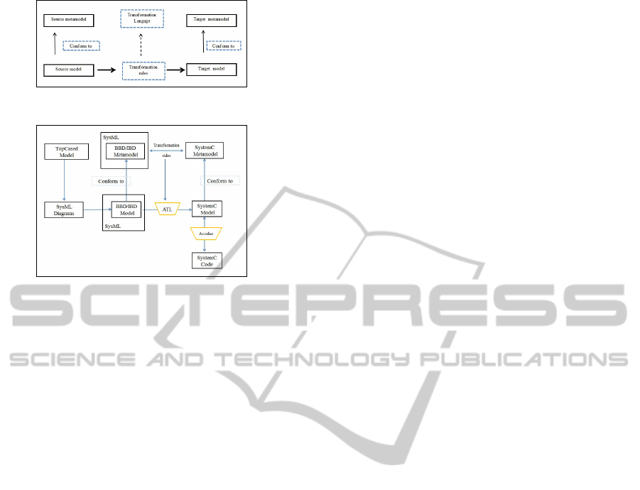
Figure 1: Model Transformation.
Figure 2: Approach Transformations.
diagrams which will be the source models for the
transformation. Our purpose in this work is the
transformation of two diagrams: BDD and IBD di-
agrams. With model transformation “Model2Model”,
was chosen ATL language, such as language and
the transformation method allowing passing a SysML
model to a model SystemC. The application of the
methodology with ATL is based primarily on
1. The definition of the source and target metamodel.
2. The definition of the style of transformation.
3. The definition of the source model that conforms
to source metamodel.
The source metamode represent the SysML meta-
model and the metamodel target will SystemC. Both
are carried out under the metamodel formalizes of
Eclipse EMF Ecore, the different stages of implemen-
tation are shown in Figure 2.
5.5 Transformation with ATL
After the definition the metamodel of SysML, Sys-
temC and models sources of SysML diagrams, we
use ATL as transformation language models. With
the aim of achieving the previously defined rules ATL
declarative “rule” is used. ATL rule is characterized
by two mandatory elements:
1. A pattern on the source model “from” with a pos-
sible constraint.
2. One or more grounds of the target model “to” that
explain how target elements are initialized from
the corresponding source element.
When creating a target item from a source element,
ATL retains a traceability link between the two ele-
ments, this link is used to initialize a target item in the
“to” match as seen in Listing 2.
The ATL following code shows an example of the
rules used in the ATL model transformation
Listing 1: Rule model to model.
rule Mod e l 2S C M o d e l {
from s y s ml : MM U M L ! M odel (
sysml . o cl I s Ty p e Of ( M MUML ! M o d e l )
)
to s c M o del : M M Sy s t em C ! SCM o d e l (
name < - s y s m l . name
)
}
rule Pa c k a g e _ B D D 2 S y s te m C_ M ai n {
from
BDD : M M UML ! P a c kag e (
BDD . o c l Is T y pe O f ( M M U M L ! Pa c k a g e )
)
to
Top : M MS y s t em C ! S C _ o bj e c t (
name < - BDD . n ame ,
ow n e rS c Mo d e l < - B DD . g e tMo d e l ()
)
}
5.6 Code Generation
Acceleo is a language code generator which allows
generating structured file from an Eclipse Modeling
Framework(EMF) (Nicolescu et al., 2011) model, the
output is a text that can be a programming language or
other formalism. Acceleo requires defining an EMF
metamodel and a model conforming to metamodel
that will result into text.
Once this definition is done, then we can execute
the code generator, in our example, we have the meta-
model and model of SystemC for code generation, we
need to create an Acceleo project and configure the
workflow necessary to code generation specifying the
link between the generator, the metamodel and model.
After it is needed to define the Template code us-
ing the keywords of SystemC language and attributing
information from the SystemC model of transforma-
tion. In the first line of Acceleo code we are importing
the metamodel so that the generator knows the struc-
ture of our model. The important concept to define
Acceleo is also called Template, it is the smallest unit
identified in a template file, and allows to define the
main reference for the workflow order to collect infor-
mation from the necessary to model code generation.
Figure 3 illustrates the SysML2SystemC code.
6 CASE STUDY
This section discusses a case study with the aim to
present the general statute-book described to spec-
MODELSWARD2014-InternationalConferenceonModel-DrivenEngineeringandSoftwareDevelopment
558
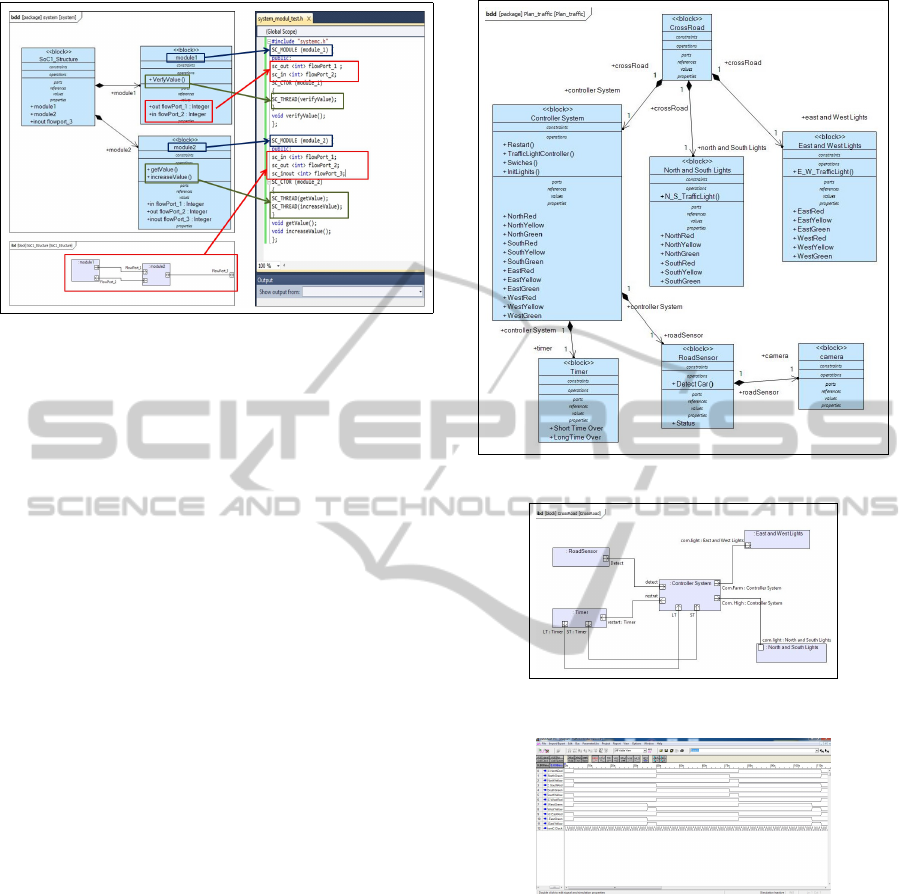
Figure 3: Code generation SysML To SystemC.
ify the behavior of road intersection signals. A road
intersection traffic light system is typically realized.
The state sequence of the car flow in the cross-
road is the base of the traffic behavior, some addi-
tional features have been added to make this work-
bench complex enough to measure meaningful eval-
uations of development system properties. They are
managed by a system that synchronizes the color
changes of the different junction lights. The traffic-
light colors are managed by a controller which de-
pends on the number of cars waiting to cross the
junction. The methodology and code generator pre-
sented were used for example to show it, use BDD
with six blocks. The first block is the most ab-
stract level of the modeling Crossroads block named
CrossRoad represents the system as a whole, it is
composed of three sub-blocks(“Controller System,
NorthandSouthLights, EastandWestLights”)and sub-
sub blocks (“Timer, Road Sensor , Camera”). Figure
4 illustrates the crossroads top level modeling.
To represent the internal structure of the Cross-
roads block by IBD. The diagram shows the flow
ports, the port management allow continuous mov-
ing the direction of Controller System and the port of
other parts (i.e. “NorthandSouthLights, EastandWest-
Lights”). Figure 5 shows the IBD diagram.
6.1 Simulation Results
When SystemC code is successfully generated from a
SysML representation, the subsequent step is to sim-
ulate and eventually synthesize code. The software
“DataSheet Pro”, is a tool selection for simulation.
The code which was generated from the SysML rep-
resentation of the crossroads system in Figure 4 and
5, was used as input for the code simulator and re-
sults in Figure 6. The simulator shows the state of
each light as true and false values through the time.
Figure 4: Top level modeling.
Figure 5: IBD of Crossroads.
Figure 6: Graph from code simulation.
There we can verify that no green light on North and
South lights is turned on when there is also a green
light on the East and West lights. The timer for the
crossfires is managed by a controller system which
at each start up, initializes a clock that measures
the duration for each crossfire color: red (36 Sec.),
yellow (4 Sec.), and green (36 Sec.), then it sends
the value to NorthandSouthLights and EastandWest-
Lights, based on the given entries “NorthRed, North
Yellow,...WestGreen”.
AnApproachbasedonSysMLandSystemCtoSimulateComplexSystems
559

7 CONCLUSIONS AND FUTURE
WORK
Previous researches demonstrated that the passage of
UML to other languages of the co-design is possi-
ble. In our work we have used SysML and Sys-
temC languages as alternatives to specify and simu-
late complex systems. SysML is popular and allows
the modelling of the software and hardware systems
with a high level of abstraction by ignoring the de-
tails of the implementation. In this paper we have
proposed an approach to translate SysML diagrams
to SystemC executable specifcations. The work de-
scribes a transformation from SysML structure dia-
grams to SystemC code, based on XMI files and Text
files. SystemC code is generated as text files automat-
ically and can be used for simulation. The translations
between models are traditionally done manually, with
the risk of human error such as missing and chang-
ing parts of the system and also SystemC syntax er-
ror. We illustrate the practicability of our approach by
case studies implemented on Topcased platform us-
ing ATL and Acceleo tools. Obtained results of ex-
perimentations and simulations are encouraging. In
future, we plan to investigate SystemC code genera-
tion from other SysML diagrams like Activity, State
Machine and Sequence behaviour diagrams allowing
the translation of more aspects of a system.
REFERENCES
(2012). IEEE Standard for Standard SystemC Language
Reference Manual. IEEE Std 1666-2011 (Revision of
IEEE Std 1666-2005), pages 1–638.
Black, D. C. (2010). SystemC: From the ground up, vol-
ume 71. Springer.
Bombino, M. and Scandurra, P. (2012). A model-driven co-
simulation environment for heterogeneous systems.
International Journal on Software Tools for Technol-
ogy Transfer, pages 1–12.
Bouquet, F., Gauthier, J., Hammad, A., and Peureux, F.
(2012). Transformation of SysML structure diagrams
to VHDL-AMS. In Design, Control and Software Im-
plementation for Distributed MEMS (dMEMS), 2012
Second Workshop, pages 74–81. IEEE.
Boutekkouk, F. (2010). Automatic SystemC code genera-
tion from UML models at early stages of systems on
chip design. International Journal of Computer Ap-
plications, 8(6):10–17.
Elsheikh, A., Widl, E., Pensky, P., Dubisch, F., Brychta,
M., Basciotti, D., and M
¨
uller, W. (2013). Modelica-
enabled rapid prototyping via TRNSYS. In BS2013,
The 13th International Conference of the Interna-
tional Building Performance Simulation Association.
Garro, A., Parisi, F., and Russo, W. (2013). A Process Based
on the Model-Driven Architecture to Enable the Defi-
nition of Platform-Independent Simulation Models. In
Simulation and Modeling Methodologies, Technolo-
gies and Applications, pages 113–129. Springer.
Gascue
˜
na, J. M., Navarro, E., and Fern
´
andez-Caballero, A.
(2012). Model-driven engineering techniques for the
development of multi-agent systems. Engineering Ap-
plications of Artificial Intelligence, 25(1):159–173.
Hause, M., Stuart, A., Richards, D., and Holt, J.
(2010). Testing safety critical systems with SysM-
L/UML. In Engineering of Complex Computer Sys-
tems (ICECCS), 2010 15th IEEE International Con-
ference on, pages 325–330. IEEE.
Jain, V., Kumar, A., and Panda, P. (2012). Exploiting UML
based validation for compliance checking of TLM 2
based models. Design Automation for Embedded Sys-
tems, 16(2):93–113.
Nicolescu, G., O’Connor, I., and Piguet, C. (2011). De-
sign technology for heterogeneous embedded systems.
Springer Publishing Company, Incorporated.
Nikiforova, O., Pavlova, N., Gusarovs, K., Gorbiks, O.,
Vorotilovs, J., Zaharovs, A., Umanovskis, D., Se-
jans, J., et al. (2012). Development of the Tool
for Transformation of the Two-Hemisphere Model to
the UML Class Diagram: Technical Solutions and
Lessons Learned. In Proceedings of the 5th Interna-
tional Scientific Conference Applied Information and
Communication Technology, pages 11–19.
Pontisso, N. and Chemouil, D. (2006). Topcased combin-
ing formal methods with model-driven engineering. In
Automated Software Engineering, 2006. ASE’06. 21st
IEEE/ACM International Conference on, pages 359–
360. IEEE.
Rao, B. H. and Padmaja, K. (2013). Study of Modern Mod-
eling Techniques for Model Based Systems Engineer-
ing Methodologies. International Journal of Engi-
neering, 2(8).
Riccobene, E. and Scandurra, P. (2012). Integrating the
SysML and the SystemC-UML profiles in a model-
driven embedded system design flow. Design Automa-
tion for Embedded Systems, pages 1–39.
Riccobene, E., Scandurra, P., Bocchio, S., Rosti, A.,
Lavazza, L., and Mantellini, L. (2009). SystemC/C-
based model-driven design for embedded systems.
ACM Transactions on Embedded Computing Systems
(TECS), 8(4):30.
Scholtz, B., Calitz, A., and Snyman, I. (2013). The usability
of collaborative tools: application to business process
modelling. In Proceedings of the South African Insti-
tute for Computer Scientists and Information Technol-
ogists Conference, pages 347–358. ACM.
Vanderperren, Y., Mueller, W., He, D., Mischkalla, F., and
Dehaene, W. (2012). Extending UML for Electronic
Systems Design: A Code Generation Perspective. In
Design Technology for Heterogeneous Embedded Sys-
tems, pages 13–39. Springer.
MODELSWARD2014-InternationalConferenceonModel-DrivenEngineeringandSoftwareDevelopment
560
