
M5AIE
A Method for Body Part Detection and Tracking using RGB-D Images
Andr
´
e Brand
˜
ao
1,2
, Leandro A. F. Fernandes
1
and Esteban Clua
1
1
MediaLab-UFF, Instituto de Computac¸
˜
ao, Universidade Federal Fluminense, CEP 24210-240 Niter
´
oi, RJ, Brazil
2
German Research Center for Artificial Intelligence (DFKI GmbH), Kaiserslautern, Germany
Keywords:
Body-part Detection, Tracking, Pose Classification, AGEX, ASIFT, Depth Images, Medial Axis.
Abstract:
The automatic detection and tracking of human body parts in color images is highly sensitive to appearance
features such as illumination, skin color and clothes. As a result, the use of depth images has been shown to
be an attractive alternative over color images due to its invariance to lighting conditions. However, body part
detection and tracking is still a challenging problem, mainly because the shape and depth of the imaged body
can change depending on the perspective. We present a hybrid approach, called M5AIE, that uses both color
and depth information to perform body part detection, tracking and pose classification. We have developed
a modified Accumulative Geodesic Extrema (AGEX) approach for detecting body part candidates. We also
have used the Affine-SIFT (ASIFT) algorithm for feature extraction, and we have adapted the conventional
matching method to perform tracking and labeling of body parts in a sequence of images that has color and
depth information. The results produced by our tracking system were used with the C4.5 Gain Ratio Decision
Tree, the Na
¨
ıve Bayes and the KNN classification algorithms for the identification of the users pose.
1 INTRODUCTION
Human body part detection, tracking and pose classi-
fication are challenging tasks because a humans shape
varies from one person to another. Humans have dif-
ferent skin colors; their clothes can also vary in both
color and shape, and movement patterns can differ
from person to person. Reliable results on body part
detection and tracking have been achieved by using
depth images that were captured by specific sensors
for this purpose. Depth images outperform intensity
images in the sense that they intrinsically remove ap-
pearance features such as the color of imaged ob-
jects (Plagemann et al., 2010). Additionally, depth
images provide extra information about the scene,
such as the actual geometry of the objects. RGB infor-
mation is also used for detecting and tracking human
body parts, but the combination of RGB and depth
information can be a powerful tool in this context.
RGB and depth images captured from the real
world contain a large amount of information. Much
of this information is irrelevant to human body part
detection and pose recognition. Therefore, filtering
the data is an important task, to reduce the computa-
tional load of the body part detection. Another issue
in this context is how to track the body parts in a video
sequence. Knowledge about each body part position
yields information on pose recognition.
We present a method for performing data filtering,
body part detection and tracking, and pose recogni-
tion. In our algorithm (see Fig.1), we first take the
independent RGB pixels and depth information of a
frame and produce an RGB-D image. Next, we filter
the information using a background subtraction ap-
proach that is applied to the depth values, which re-
duces the image to foreground information only. In
our case, the foreground is a person. To reduce even
more the amount of data that is used in the pose esti-
mation, we apply a medial axis transformation to the
segmented image. The output of this stage will then
be used to detect and label human body parts. With
the labeled body parts in hand, it is possible to track
each of them in the video sequence and to estimate the
positions of the body parts according to their velocity.
Human pose classification is made for each frame
using two different algorithms: the C4.5 Gain Ratio
Decision Tree (Quinlan, 1993) and the Na
¨
ıve Bayes
Classifier (Domingos and Pazzani, 1997). In our ap-
proach, the input information for the classification
stage is a set of 2D coordinates of the cells that con-
tain the tracked body parts of the subject. The size
and location of the cells is defined by a regular subdi-
vision strategy that is applied on the RGB-D image.
The name M5AIE is an acronym for each of the
367
Brandao A., Fernandes L. and Clua E..
M5AIE - A Method for Body Part Detection and Tracking using RGB-D Images.
DOI: 10.5220/0004738003670377
In Proceedings of the 9th International Conference on Computer Vision Theory and Applications (VISAPP-2014), pages 367-377
ISBN: 978-989-758-003-1
Copyright
c
2014 SCITEPRESS (Science and Technology Publications, Lda.)

used concepts in our approach: Medial Axis trans-
formation, for data filtering; Adapted AGEX, for the
body part detection; ASIFT, for the body parts track-
ing, Aligned Images (RGB-D), and Estimation, also
for tracking.
The main contributions of this paper include the
following:
• The combination of AGEX and ASIFT methods
using aligned RGB and depth images for label-
ing five major defined body parts (hands, feet and
head); and
• Track each of the body parts using an adapted
ASIFT matching algorithm.
This paper is organized as follows: Section 2
presents some of the related studies. Section 3 de-
scribes the M5AIE method. The results are presented
in Section 4. Section 5 concludes the work with a
discussion and future directions for the research.
2 RELATED WORK
Human action recognition is a related area of Com-
puter Vision that addresses motion in videos. Mota
et al. (Mota et al., 2012) introduced a video motion
indexing scheme that was based on modeling optical
flow. In their work, the authors proposed a global mo-
tion tensor descriptor for video sequences, and opti-
cal flow was described with a polynomial representa-
tion. In contrast to Mota et al.’s work, we are con-
cerned with the detection and tracking of body parts
in RGB-D image sequences and with pose identifica-
tion in single frames of the sequence.
Several Computer Vision studies have solved
movement recognition problems using either RGB
or depth images. If we consider both RGB and
depth values captured by a specific sensor and com-
bine them, the possibility of correctly handling pose-
recognition issues increases. In our work, we use
depth information for background subtraction. The
RGB information is used to produce RGB-D im-
ages that are converted to grayscale by the tracking
method.
Regarding human pose recognition, Shotton et
al. (Shotton et al., 2011) have described an approach
that is based on single depth images captured with a
Microsoft Kinect sensor. The main contribution of
Shotton’s work is to treat pose estimation as object
recognition, using an intermediate body parts repre-
sentation to find the joints with high accuracy.
An accurate pose estimator from single-depth im-
ages was described by Ye et al. (Ye et al., 2011).
These authors used a dataset as input to make the pose
estimation and presented a pose refinement scheme
that can handle pose and body size differences. In
their work, they also proposed a pose detection algo-
rithm that is view independent.
A combination of RGB and depth images (RGB-
D) has been used for different purposes. Henry et
al. (Henry et al., 2012) presented how the RGB-D im-
ages can be used to build 3D maps of indoor environ-
ments. Lai et al. (Lai et al., 2011) also used RGB-D
data to recognize instances of a previously trained ob-
ject. Endres et al. (Endres et al., 2012) used feature
descriptors to provide simultaneously the localization
and mapping (SLAM) of RGB-D cameras. Their ap-
proach was evaluated using SIFT, SURF, and ORB
descriptors. We use depth data in background sub-
traction and also in body part detection. The pixel
intensities computed from the RGB values are used
for tracking.
The usage of geodesic distances in human
body part detection was proposed by Plageman et
al. (Plagemann et al., 2010) as part of the Accumu-
lative Geodesic EXtrema points, named the AGEX
points. Ganapathi et al. (Ganapathi et al., 2010)
used AGEX for performing real time motion capture
from depth images. Both studies used depth sensors
based on a time-of-flight camera to capture the depth
data. AGEX was also used by Baak et al. (Baak
et al., 2011) for full body pose reconstruction. Al-
though these studies are very accurate when detecting
major body parts (head, hands and feet), the detection
of joints in (Plagemann et al., 2010), (Ganapathi et al.,
2010), (Baak et al., 2011) is performed as a na
¨
ıve es-
timation of their position with respect to the five main
body regions, i.e., head, hands and feet. Such an ap-
proach might fail when the imaged person is hold-
ing objects such as rackets, balls or other video game
gadgets. To avoid estimation problems, we use only
the positions of each major body part, which are first
mapped exactly where the parts are, without any esti-
mation. Considering games, which are the context of
our technique, we show that the five main body parts
are sufficient for pose classification.
AGEX-points detection is usually performed con-
sidering the whole imaged body. In contrast to the
conventional approach, we estimate the AGEX points
from the pixels of a person’s discrete medial axis. We
also perform tracking by extracting ASIFT features
and matching them between frames. Silberman and
Fergus (Silberman and Fergus, 2011) used the SIFT
algorithm on depth images for indoor scene segmen-
tation. The main goal of Silberman and Fergus was to
label objects (bed, bookshelf, floor, sofa, and table) in
a scene, while combining the depth and color images
and to obtain satisfactory results. Another study that
VISAPP2014-InternationalConferenceonComputerVisionTheoryandApplications
368
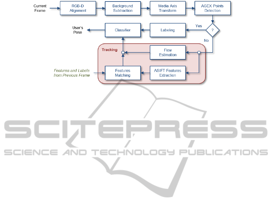
Figure 1: Flowchart of the proposed M5AIE approach applied to RGB-D images to identify the pose of the imaged subject.
See Section III for details. The question mark after the AGEX Points Detection stage verifies whether the Labeling stage of
the algorithm can be performed.
uses SIFT and depth images was presented by May et
al. (May et al., 2008). The main goal in (May et al.,
2008) was to perform environment mapping.
3 THE M5AIE METHOD
The M5AIE method aggregates different concepts;
some of them were not originally developed for de-
tecting, tracking, and pose classification. The compu-
tational flow of the M5AIE algorithm is illustrated in
Fig. 1. After the alignment of the RGB (Figure 2a)
and depth (Figure 2b) images of a given frame, we
use the Minimum Background Subtraction algorithm
(Stone and Skubic, 2011) to address most of the un-
necessary information in the frame (Subsection 3.1).
In turn, the area of the person facing the sensor (Fig-
ure 3a) is replaced by the few pixels that define its
discrete medial axis (Figure 3b) transformation (Sub-
section 3.2). The detection of body part candidates
begins by building a graph in which each pixel of the
medial axis is seen as a vertex that is connected to its
neighbors by weighted edges; each weight is given
by the Euclidean distance between a pair of pixels
(Subsection 3.3). Using this graph, body part candi-
dates are detected through the AGEX points detection
method (red points in Figure 3, Subsection 3.4). A
labeling step is performed to relate AGEX points to
their respective body parts (Subsection 3.5). When
labeling fails, the information computed in the pre-
vious frame is used in combination with the ASIFT
method for tracking the body parts into the current
frame (Subsection 3.6). Pose classification is per-
formed in the last stage of our method (Subsection
3.7).
3.1 Minimum Background Subtraction
Algorithm
The Minimum Background Subtraction algorithm is
composed of training and subtraction stages. Dur-
ing the training stage, the approach limits the back-
ground values regarding the following assumptions:
indoor environment, static background, and static po-
sition and orientation of the sensor. In this stage, a
lookup matrix with the same size as the depth image
is created to store the minimum depth values assumed
by each pixel during a frame sequence that captures
only background elements. The subtraction stage is
applied to every subsequence frame. By comparing
stored minimum values with current depth values, the
approach is capable of distinguishing background and
foreground pixels (Stone and Skubic, 2011).
Noise is typically present when the Kinect or time-
of-flight camera is used. Noise results from errors in
the distance measurements, such as when the sensor
receives multiple pieces of depth information for the
same image coordinates (Schwarz et al., 2012). In
the case of the Kinect sensor, one must also address
“shadowing”. Shadowing occurs when the depth in-
formation of the background cannot be captured by
the sensor because an object or a person blocks the
capturing of this information. Each captured noise
pixel and each pixel of the shadow receive a zero
value. Because the Minimum Background already
provides background values, we apply the same val-
ues to every shadow pixel. In this study, we call the
output of the Minimum Background algorithm a seg-
mented image. Figure 3a shows a segmented image
with the color and depth information aligned.
We chose to use this background subtraction algo-
rithm because it had the best results in previous ex-
periments (Greff et al., 2012).
M5AIE-AMethodforBodyPartDetectionandTrackingusingRGB-DImages
369

(a) RGB image (b) False-color depth information
Figure 2: A pair of images related to the same frame of a
sequence: (a) RGB information is used to color the fore-
ground pixels and in the tracking stages of our algorithm.
(b) Depth information (displayed with false-color) is used
to distinguish background and foreground pixels.
3.2 Discrete Medial Axis Through
Distance Transformation
The 2D medial axis transform constitutes finding the
centers of the maximum disks that can fit inside of an
object (Blum, 1967). A disk is maximal if it is not
contained by any other such disk. The set of all cen-
ters is called the medial axis. When working with
digital images, the discrete medial axis of a shape
can be computed from the ridge of the discrete dis-
tance transformation (Gonzalez and Woods, 2008).
Because the discrete medial axis of a discrete object
is a connected structure that is composed of a small
number of pixels inside that object, we use such a
structure to reduce the number of pixels that are to be
considered as vertices in the graph computation (Sec-
tion 3.3).
We have performed discrete medial axis extraction
by computing the discrete distance transform of the
binary image that results from the Minimum Back-
ground Subtraction (Section 3.1). In turn, we have
applied mean-C adaptive local thresholding (Gonza-
lez and Woods, 2008) to identify a superset of the
pixels that represent the ridge of the distance trans-
form. From the superset, one could extract the ridge
pixels. However, in practice, the exact ridge pixels are
not necessary in subsequent steps of our algorithm be-
cause the cardinality of the superset is already much
smaller than the cardinality of the original set of pix-
els that represent the users body. A segmented image
and the result of the discrete medial axis (superset)
extraction through a distance transformation are pre-
sented by Figure 3.
3.3 Graph Construction based on Depth
Image
We use image pixel coordinates to build a graph in lin-
ear time, as implemented in Schwarz et al. (Schwarz
et al., 2012). In such a case, two vertices are consid-
ered to be neighbors if the corresponding pixels are
separated by a maximum distance threshold δ. The
graph is represented as G
t
= (V
t
, E
t
), where V
t
are the
vertices related to pixels in the image plane, and E
t
are the edges that connect the vertices. We follow
Plagemann et al.’s strategy (Plagemann et al., 2010)
to connect two vertices and Schwarz et al.’s scheme
to weight the edges with the Euclidean distance of
the imaged surface points related to the vertices. For-
mally, Schwarz et al. define the edges as:
E
t
=
(x
i j
, y
kl
) ∈ V
t
×V
t
|
x
i j
− x
kl
2
< δ ∧
(i, j)
T
− (k, l)
T
∞
≤ 1
, (1)
where
k
·
k
2
is the Euclidean distance,
k
·
k
∞
is the max-
imum norm, and (i, j)
T
and (k,l)
T
are the 2D coor-
dinates of the points x
i j
and x
kl
in the depth image.
As a consequence of computing the medial axis, the
original body can be represented by patches of un-
connected pixels. To solve this problem, we used a δ
value that connects the disconnected parts. The value
of δ was obtained from experiments in which the dis-
tance between the unconnected pixels was measured.
3.4 Accumulative Geodesic Extrema
Points
Figure 3 illustrates a segmented RGB-D image (Fig-
ure 3a), which is used as input to a discrete me-
dial axis transform. Figure 3b illustrates the im-
age from the preprocessing stage that is used to gen-
erate the graph. The Accumulative Geodesic Ex-
trema Points (AGEX) are selected while considering
the distances of the points according to the edges
that connect the vertices in the graph G
t
(Plagemann
et al., 2010). This method maximizes the distances
of the points using the Dijkstra algorithm (Dijkstra,
1959). To accomplish this goal, the first AGEX
point (AGEX
1
) is chosen to be the closest point to the
centroid (c
t
) of the human body. The shortest distance
between c
t
and all of the other vertices that belong to
graph G
t
are calculated with Dijkstra’s algorithm, and
the vertex with the longest distance among all of the
shortest distances is selected as AGEX
2
.
Once the second AGEX point is selected, a zero
cost edge between AGEX
1
and AGEX
2
is added to
graph G
t
. The aim of adding this edge is to not al-
low the selection of the same point in a subsequent
call of the Dijkstra algorithm. The steps of finding the
vertex that has the longest distance in all of the short-
est distances that are calculated and adding a zero
edge between the two points are repeated consider-
ing AGEX
2
instead of AGEX
1
, and so on until AGEX
6
VISAPP2014-InternationalConferenceonComputerVisionTheoryandApplications
370

can be found. The red points in Figure 3 correspond
to the AGEX points of the imaged subject.
Schwarz et al. (Schwarz et al., 2012) approximate
the geodesic distances of AGEX
k−1
and AGEX
k
by
d
G
=
∑
e∈SP(x,y)
w(e), (2)
where SP(x, y) contains all of the edges along the
shortest path between the vertices x and y.
3.5 Body Part Labeling
The initialization step for body part labeling com-
prises a person facing the camera for a few seconds
and taking a snapshot on a T-pose (the T-pose can
be seen in Figures 2 and 3). The first six AGEX
points correspond to the centroid, head, hands and
feet, not necessarily selected in that order. They are
labeled according to the relative position to the cen-
troid (AGEX
1
). Until this stage of the process, the
hands, feet and head have not been labeled.
Because AGEX
1
is the centroid (c
t
), we can de-
fine the lower and upper parts of the body and sepa-
rate the other points (from AGEX
2
to AGEX
6
) accord-
ing to their coordinate values. Assuming the T-pose,
the point that has the highest upper value compared
with the centroid is considered to be the head. The
two points below the centroid are the right and left
feet. Finally, the other two points are the right and left
hands. These labeled points are considered in the ini-
tialization step, and they are detected at the beginning
of the image sequence. As long as this configuration
remains unchanged, the AGEX method is used to de-
tect and label each of the body parts. However, when
the described configuration changes, then we start to
use the ASIFT method, using time sequence informa-
tion that is based on point estimations to track labels
from one frame to another, as described in the next
subsection.
(a) Segmented RGB-D image (b) Input image for graph generation
Figure 3: A discrete medial axis transformation (b) is ap-
plied in the segmented RGB-D image (a) to reduce the num-
ber of pixels to be considered during the AGEX-graph con-
struction. The red pixels in (a) and (b) are the AGEX points.
3.6 ASIFT-based Tracking of AGEX
Points
The ASIFT algorithm was proposed by Morel and
Yu (Morel and Yu, 2009) for affine-invariant image-
feature extraction. The ASIFT method expects
grayscale images as input. The technique transforms
the input image by applying tilts and rotations for
a small number of latitude angles. Those transfor-
mations make ASIFT features affine invariant. Each
transformed image is submitted to feature extraction
using the SIFT algorithm. See (Morel and Yu, 2009)
for more details. The extracted features can be used
in image matching applications.
In our tracking strategy, ASIFT is used to identify
the features in the frame t that are related to the AGEX
points identified in frame t − 1. However, ASIFT can-
not be used directly in tracking due to some practical
issues: (i) in the case of background segmented im-
ages, ASIFT detects too many features in the border
of the foreground region; (ii) there is not necessar-
ily a matching feature for every pixel from one im-
age to another; (iii) the time execution increases as
the input images become larger; and (iv) ASIFT can
match two features whose positions are far away from
an expected conservative maximum distance. We ad-
dressed these problems using the following heuristics.
3.6.1 Blurring the Background of Sub-images
With the background pixels colored with black and
the RGB color of the body pixels converted to a
grayscale, the ASIFT method usually detects features
only at the frontier between the foreground and the
background regions. To solve this issue, we fill the
background pixels of the sub-images with blurred
RGB values that are computed according to their col-
ored neighbor pixels. The blurring process makes
the sub-images have smoother transitions in intensi-
ties among foreground and background pixels. As a
result, the contrast inside the portions of the image
that are related to the person’s body become more
significant, which improves the detection of ASIFT
features inside the foreground region. Examples of
background-blurred sub-images are shown in Figure
5. These examples were computed based on the sub-
images in Figure 4. These background-blurred im-
ages are the input for the ASIFT, after they are con-
verted to grayscale. The blurring method is performed
as follows: The blurring method is performed as fol-
lows: The blurring method is performed as follows:
Step 1. Create a list of background pixels and keep it
sorted in descending order with regard to the number
of foreground (black) 8-connected neighbor pixels of
M5AIE-AMethodforBodyPartDetectionandTrackingusingRGB-DImages
371
each entry.
Step 2. Replace the RGB value of the first pixel in
the list by the mean RGB values of its neighboring
foreground pixels. Remove such a pixel from the list,
treat it as a foreground pixel and update the order of
the remaining pixels.
Step 3. Go to the first step or stop when there is no
more background pixel to be processed.
3.6.2 Searching in a Region instead of Searching
for Coordinates Only
This heuristic is related to the problem that there is not
necessarily a matching feature for every pixel from
one image to another. As a consequence of this as-
sumption, a body part position can be lost if we con-
sider only its coordinates. We handle this problem in
the following way: if there is no body part matching
feature from the sub-image at t −1 with the sub-image
at t, then we search for the point P, which is the near-
est body feature in t − 1 that has a match in t. We
filter the matching result, considering P as the body
part and its matching feature in t as the final result.
Considering the person’s movement, the body part
in frame t − 1 can be located anywhere in a region
of the frame t. The region is delimited according to
a distance from the point in t − 1 and the frame at t.
This adaptation is not in ASIFT method but it is in the
matching point output. The reference implementation
provided by Morel and Yu (Morel and Yu, 2009) re-
turns all matching ASIFT features from an image in
t − 1 and t. Our specialized matching scheme, on the
other hand, returns only a single feature in a region in
t − 1 that is related to a feature in t.
3.6.3 Use of Tiny Images instead of Complete
Frames
To avoid the heavy computational load of ASIFT ap-
plied to the whole image, we apply ASIFT on five tiny
images that contain the body parts in frame t −1 and
the sub-images of the regions in which the same body
parts can possibly be found in frame t. It is important
to note that the location and labeling of the body parts
in frame t −1 is always known. In the case of the
first frame, the T-pose will guarantee the success of
the labeling process. In subsequent frames, the body
parts will be found by labeling or tracking processes
that are performed in functions of frame t −2. Figure
4 illustrates the five sub-images at frame t − 1. We
assume that each body part does not move too much
from one frame to the next frame. Each of the tiny im-
ages has a different body part in it, which allows the
matching features provided by ASIFT to be in approx-
imately the same region from one image to another.
(a) head (b) left hand (c) right hand (d) left foot (e) right foot
Figure 4: Sub-images of the detected five main body parts.
(a) head (b) left hand (c) right hand (d) left foot (e) right foot
Figure 5: Background-blurred version of the sub-images
presented in Figure 4.
3.6.4 Body-parts Position Estimation
To assert the consistency of the matching of ASIFT
features in the sub-images of consecutive frames, we
estimate the expected location of the feature in frame t
using the uniform linear motion equation considering
its location in frames t −1 and t −2. The estimation
is made using the following:
s
t
= s
t−1
+ vt, (3)
where s
n−1
is a coordinate value (x or y) of the feature
in the previous frame, v is the velocity value calcu-
lated from (4), and t is a constant related to time. The
velocity value is computed as:
v =
∆S
∆T
, (4)
where ∆T is constant for our case.
The uniform linear motion displacement of each
coordinate is computed using:
∆S = s
t−2
− s
t−1
, (5)
In our framework, the acquisition of the color and
the depth images is performed by the same appara-
tus (a Kinect), and the RGB-D image alignment is
performed by Kinect SDK. However, because of the
asynchronous nature of the image sensors, the final
aligned RGB-D image could be formed. As a result,
background color pixels can be incorrectly mapped to
foreground regions. Figure 6 illustrates an extreme
case in which many depth pixels of the human body
were painted with color information from the back-
ground.
To make the proposed matching procedure suit-
able for tracking, we found four major situations to
be addressed, which can be divided into two groups:
(i) the matched ASIFT feature and the point estimated
with equation (3) correspond to well-mapped back-
ground pixels; (ii) the matched ASIFT feature re-
sides in the well-mapped background while the esti-
mated point is part of the users body; (iii) the matched
VISAPP2014-InternationalConferenceonComputerVisionTheoryandApplications
372

ASIFT feature belongs to the human body, and the es-
timated point is part of the background; and (iv) both
the matched ASIFT feature and the estimated point
correspond to the actual body.
In the first case, our method searches the body part
pixel that is closest to the ASIFT feature found. The
second case is when the resulting ASIFT feature is
part of the background and the estimated point is part
of the body, which generates two sub-cases: (a) if
the distance between the two points is smaller than
a threshold, then the estimated point will be the final
result; and (b) if the distance between the two points is
larger than a threshold, then the nearest point from the
ASIFT feature that belongs to the human body will be
the result.
The third case occurs when the ASIFT feature be-
longs to the human body and the estimated point be-
longs to the background. In this case, there are two
sub-cases, which are similar to the previous case: (i) if
the distance between the two points is smaller than
the threshold, then the ASIFT matching feature will
be the final result; and (ii) if the distance between
the two points is larger than the threshold, then the
nearest point from the ASIFT feature that belongs to
the human body will be the result. Finally, the forth
case is when the ASIFT matching feature and the es-
timated point belong to the human body and, again,
we have two sub-cases: (i) if the distance between
the two points is smaller than the threshold, then the
ASIFT feature is the final result; and (ii) if the dis-
tance between the two points is larger than the thresh-
old, then a point whose coordinates are the average of
the two points is generated, and this middle point will
be the final result.
The four defined heuristics are necessarily be-
cause the alignment of the RGB and the depth infor-
mation could consider images that are acquired at dif-
ferent times. This alignment is provided by the appa-
ratus. If there was no interval for producing RGB-D
images, the presented heuristics would be unneces-
sary.
3.7 Pose Classification
Classification techniques are used in our work to iden-
tify categorical labels such as “Pose A” and “Pose B”
for the current subject, according to the position of
each of the body parts detected or tracked in a given
image of the sequence.
We have performed pose classification using
three different algorithms: C4.5 Gain Ratio Deci-
sion Tree (Quinlan, 1993), the Na
¨
ıve Bayes clas-
sifier (Domingos and Pazzani, 1997) and the KNN
Classifier (Cover and Hart, 1967). These algorithms
Figure 6: Kinect performs asynchronous acquisition of
RGB and depth images. As a result, the quality of the RGB-
D alignment procedure performed by Kinect’s API can be
affected by rapid movements of the user, which leads to in-
consistent RGB-D image formation.
were selected due to their low computational load and
simplicity, making them suitable for real-time appli-
cations. The main difference between the first two
classifiers is that while C4.5 is a decision tree clas-
sifier, the Na
¨
ıve Bayes is based on the Bayes rule
of conditional probabilities. In decision trees, at-
tributes are tested, and the final classifications are at
the leaves. In this approach, the attributes have a high
level of dependency with each other. However, the
Na
¨
ıve Bayes classifier evaluates each attribute indi-
vidually, considering them to be independent.
In 1967, Cover and Hart (Cover and Hart, 1967)
introduced the K-Nearest Neighbor as a pattern clas-
sifier. A training set is built by tuples and a tuple
X, whose class is unknown, is then tested. The tu-
ple X is compared with each of the training tuples.
The K closest tuples to X are considered to predict
its class. “Closeness” is considered a distance metric,
and it can be calculated, for example, with the Man-
hattan, Chebyshev or Euclidean distance. The three
distances were selected because they use the verti-
cal and horizontal coordinates system, which is used
by the M5AIE method to generate tuples. The un-
known class of X is assigned to the most common
class among its K nearest neighbors.
3.7.1 Bounding Box and Grid
In this work, the algorithms receive as input the la-
bels and the locations of the body parts according to
an N × N grid that is defined inside the bounding box
that contains the whole body of the imaged subject.
Figure 7 shows the grid squares with N = 8. A bound-
ing box was used to identify the cell number of the
body parts. The bounding box provides the relative
positions according to the detected human body. This
approach makes it possible to identify the cell num-
ber of the body parts, independently of their occupied
positions in the whole segmented image.
All the classification algorithms require the exe-
M5AIE-AMethodforBodyPartDetectionandTrackingusingRGB-DImages
373
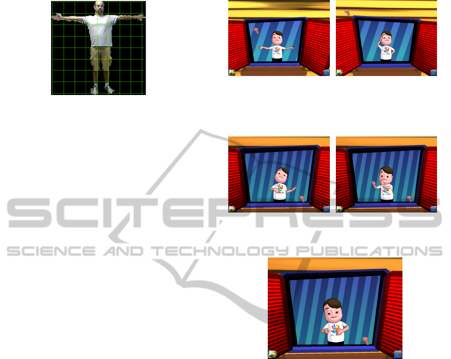
Figure 7: A bounding box limits the human body and it is
divided into N × N cells. In our experiments, N = 8.
cution of a training stage to build a model to be used
during the classification of the poses. In our work, the
dataset used both for training and testing comprises
the grid-coordinates that body parts assume at each
frame of a set of image sequences produced for this
work and the manual classification of the pose in each
frame. In the classification procedure, a tuple consti-
tutes a sequence in which the cell position of every
individual body part is described in the same order
that appears in the attributes definition.
4 EXPERIMENTS AND RESULTS
The described approach was implemented in Python
and was evaluated on real image sequences. The
ASIFT algorithm was implemented in C++. We used
the reference implementation provided by Morel and
Yu (Morel and Yu, 2009). We used OpenCV to per-
form the distance transformation, adaptive threshold-
ing and other basic image processing procedures. The
image sequences were collected using a Kinect sen-
sor, which provides both depth and color images with
a 640 × 480 pixel resolution. The resolution of the
tiny images was set to 80 × 80. The goal of this ex-
perimental evaluation is to demonstrate the following:
• The modified AGEX can be used for body part
detection and labeling in all of the frames of the
sequence that have the expected AGEX point con-
figuration described in Section 3;
• The ASIFT algorithm can be used for tracking ob-
jectives; and
• The output of the combined techniques can be
used for human pose classification.
We previously collected sequences with human
poses that were inspired in a game developed by our
research group (Brand
˜
ao et al., 2010). The poses
are: T-pose, dancing (left hand on hip and right hand
on head), playing guitar, playing flute and playing
drums. Two other movements, which were not re-
lated to the game, were also included: punching and
kicking.
(a) T-pose (b) Dancing
Figure 8: Illustration of T-pose and dancing human poses in
a game developed by our research group that inspired our
experiments.
(a) Play guitar (b) Play flute
Figure 9: Illustration of Play guitar and Play drums human
poses.
Figure 10: Illustration of the Play drums human pose.
We characterize the classes as the following: The
T-pose constitutes a person with both arms and hands
at the same level as the shoulders. In the dancing
class, one of the hands is on the head; the other hand is
on the hip, and one or both feet are on the ground. As
a consequence, we have six combinations of poses for
the class dancing: (i) left hand on the head and feet on
the ground; (ii) left hand on the head and moving left
foot; (iii) left hand on the head and moving right foot;
(iv) right hand on the head and feet on the ground;
(v) right hand on the head and moving right foot; and
(vi) right hand on the head and moving left foot. All
of the six poses have the same class, which is danc-
ing.
In the playing guitar class, the user imitates the
moves of playing an instrument, shaking the right
hand while the left hand stays at the same level as
his/her shoulders. The playing drums class is when
the user shakes his/her hands up and down alternately.
There are two possible poses for the punch class, both
of which have feet on the ground: (I) right hand and
VISAPP2014-InternationalConferenceonComputerVisionTheoryandApplications
374

Table 1: Image sequence evaluation for Volunteer A.
Sequence Movement Number Track
Number of Images to the
end
Seq. A1 dancing (i) 140 yes
Seq. A2 dancing (i) 116 yes
Seq. A3 dancing (ii) 100 yes
Seq. A4 playing guitar 140 yes*
Seq. A5 playing drums 190 yes*
Seq. A6 playing drums 130 yes*
Seq. A7 playing drums 130 yes*
Seq. A8 punch (I) 84 yes
Seq. A9 punch (I) 81 yes**
Seq. A10 kick (a) 66 yes
Seq. A11 dancing (iii) 58 yes
Seq. A12 dancing (ii) 68 yes
Seq. A13 kick + punch (A) 57 yes
Seq. A14 dancing (iv) 104 yes
Seq. A15 dancing (v) 152 yes
Seq. A16 dancing (vi) 98 yes
Seq. A17 kick + punch (D) 55 yes
*Tracked until the end of the sequence, but there
was a problem in the presence of self-occlusion.
**Problem caused by movement velocity.
Table 2: Image sequence evaluation for Volunteer B.
Sequence Movement Number Track
Number of Images to the
end
Seq. B1 dancing (i) 99 yes
Seq. B2 dancing (iv) 84 yes
Seq. B3 dancing (iii) 84 yes
Seq. B4 dancing (ii) 62 yes
Seq. B5 dancing (v) 72 yes
Seq. B6 dancing (vi) 79 yes
Seq. B7 punch (I) 65 yes
Seq. B8 punch (II) 75 yes
Seq. B9 kick (b) 70 yes
Seq. B10 kick (a) 79 yes
Seq. B11 kick + punch (C) 73 yes
Seq. B12 kick + punch (D) 74 yes
Seq. B13 kick + punch (B) 99 yes
Seq. B14 kick + punch (A) 97 yes
(II) left hand. Similar to the punch, the kick class can
be made with: (a) right foot and (b) left foot, with both
hands below the centroid. The kick + punch class can
be made in four different poses: (A) kick with left foot
and punch with left hand; (B) kick with left foot and
punch with right hand; (C) kick with right foot and
punch with right hand; and (D) kick with right foot
and punch with left hand.
We used three different volunteers in our exper-
iments: A, B and C. For each user, we collected a
different number of sequences. Volunteer A is male,
1.76 meters tall, and has dark hair. Table 1 shows the
collected sequences with Volunteer A. We collected
Table 3: Image sequence evaluation for Volunteer C.
Sequence Movement Number Track
Number of Images to the
end
Seq. C1 dancing (i) 48 yes
Seq. C2 dancing (iv) 69 yes
Seq. C3 dancing (iii) 45 yes
Seq. C4 dancing (ii) 54 yes
Seq. C5 dancing (v) 54 yes
Seq. C6 dancing (vi) 45 yes
Seq. C7 punch (I) 90 yes
Seq. C8 punch (II) 88 yes
Seq. C9 kick (b) 49 yes
Seq. C10 kick (a) 54 yes
Seq. C11 kick + punch (C) 90 yes
Seq. C12 kick + punch (D) 100 yes
Seq. C13 kick + punch (B) 85 yes
17 sequences with all of the classes.
Volunteer B is male, 1.90 meters tall and has blond
hair. Volunteer B made 14 different sequences in four
classes, all of them without self-occlusion. All of the
possible poses for each of the four classes were col-
lected. Table 2 details each of the collected poses
from Volunteer B.
Volunteer C is female, 1.66 meters tall and has
dark hair. Similar to Volunteer B, we collected se-
quences of four different classes with Volunteer C.
Additionally, no problem was detected during the col-
lection of the poses, which shows that the M5AIE
method works well in sequences that do not have self-
occlusions. We collected 13 sequences with Volunteer
C because we wanted to test fewer training tuples with
the pose kick + punch (A).
We observed that the M5AIE method had prob-
lems with poses that had self-occlusions. The prob-
lems were detected in the playing guitar and playing
drums poses. This problem detection was crucial for
the collection of the other users sequences; as a result,
we avoided collecting these poses. However, we kept
the results to make the tuples and test the classifica-
tion algorithms. In only one sequence, the tracking
method had problems that were caused by the move-
ment velocity, but the pose classification was not af-
fected.
The dataset that was used for both the training and
testing comprises the grid-coordinates that body parts
assume at each frame of a set of image sequences that
were produced for this work and the manual classifi-
cation of the pose in each frame. In (Brand
˜
ao et al.,
2013), we show how we varied the number of cells of
the grid in each frame.
The resume of the experiments of (Brand
˜
ao et al.,
2013) is described as follows: we used three volun-
teers that had very different biotypes to collect the
M5AIE-AMethodforBodyPartDetectionandTrackingusingRGB-DImages
375

pose sequences with variations in the numbers of im-
ages and poses. In addition to the different classifi-
cation algorithms, we tested three types of distances:
Manhattan, Chebyshev and Euclidean. In all the ex-
periments with the KNN Classifier, as the k value
increased, the percentage of correctly classified in-
stances decreased. This happens because if we con-
sider a high number of nearest points, we start to ob-
serve very different points that could be far away from
the considered point and they affect the final result.
We consider KNN with k = 1 and the Manhattan dis-
tance as the winner because it provided the best re-
sults in all of the experiments. We believe that the
coordinates of the five main body parts can be nor-
malized in the bounding box because, in our exper-
iments, as long as we increased the division of the
used grid (8, 16, 32 and 64), the results became bet-
ter. However, we also believe that there is a limit
when dividing the grid. Further experiments should
be performed to find the value for which the division
does not make sense anymore. Further experiments
should be performed to prove that normalized coordi-
nates could be a good choice in the usage of a bound-
ing box for cell definition.
5 CONCLUSIONS AND FUTURE
WORK
We presented the M5AIE method for detecting and
tracking five main parts of the human body (head,
hands and feet) in sequences of RGB-D images. Our
method generates tuples that were used with three
different classifiers: the C4.5 Gain Ratio Decision
Tree, the Na
¨
ıve Bayes and the KNN Classifier. The
proposed approach combines an effective background
subtraction method, the discrete medial axis transfor-
mation, in the construction of simpler graphs to be
used in the detection of AGEX points, heuristics for
labeling, and ASIFT-based tracking of labeled struc-
tures.
We investigated how to adapt the ASIFT method
for tracking objectives and showed that it is possible
to achieve good results with the tested movements.
The key insights of this investigation are the follow-
ing:
• ASIFT and estimation can be combined and used
for tracking objectives of movements without
self-occlusions;
• It is necessary to make improvements in the track-
ing method to use it with movements where there
is a body part occlusion;
• The RGB-D aligning procedure caused the loss of
one of the body parts during tracking. This type
of problem might not occur in the future through
the synchronous acquisition of color and depth in-
formation; and
• The used classifiers are suitable for pose classifi-
cation purposes.
The three used classifiers worked well. This re-
sult shows that the output of the tracking and labeling
stages produces qualified tuples that can be used with
the adopted classification techniques.
The proposed M5AIE algorithm was implemented
in proof-of-concept programs. At this moment, we
did not consider the computational load of this spe-
cific implementation to be a fundamental requirement
because the main goal of this work is to assert the pos-
sibility of using a hybrid technique for body part de-
tection, tracking and pose classification. We believe
that the M5AIE can be efficiently implemented and
used as part of real-time tracking solutions that are
applied to games.
The M5AIE method is limited to an indoor envi-
ronment, static background, static position and orien-
tation of the sensor and to single-user segmentation.
Experiments showed that, to be correctly tracked, se-
quences must not have body part occlusions. Fu-
ture work will include the application of the M5AIE
method with partial occlusion treatment between two
users, and the use and comparison of more classifiers
for pose recognition with multiple subjects.
REFERENCES
Baak, A., M
¨
uller, M., Bharaj, G., Seidel, H.-P., and
Theobalt, C. (2011). A data-driven approach for real-
time full body pose reconstruction from a depth cam-
era. In IEEE 13th International Conference on Com-
puter Vision, pages 1092–1099, Bacelona, Spain.
Blum, H. (1967). A transformation for extracting new de-
scriptors of shape. Models for the perception of speech
and visual form, 19(5):362–380.
Brand
˜
ao, A., Brand
˜
ao, L., Nascimento, G., Moreira, B.,
Vasconcelos, C. N., and Clua, E. (2010). Jecripe:
stimulating cognitive abilities of children with down
syndrome in pre-scholar age using a game approach.
In Proceedings of the 7th International Conference
on Advances in Computer Entertainment Technology,
ACE ’10, pages 15–18, New York, NY, USA. ACM.
Brand
˜
ao, A., Fernandes, L. A. F., and Clua, E. (2013). A
comparative analysis of classification algorithms ap-
plied to m5aie-extracted human poses. In Proceedings
of the XII Brazilian Symposium on Games and Digital
Entertainment, SBGAMES ’13.
Cover, T. and Hart, P. (1967). Nearest neighbor pattern clas-
sification. Information Theory, IEEE Transactions on,
13(1):21–27.
VISAPP2014-InternationalConferenceonComputerVisionTheoryandApplications
376

Dijkstra, E. (1959). A note on two problems in connexion
with graphs. Numerische Mathematik, 1(1):269–271.
Domingos, P. and Pazzani, M. (1997). On the optimality
of the simple bayesian classifier under zero-one loss.
Machine learning, 29(2):103–130.
Endres, F., Hess, J., Engelhard, N., Sturm, J., Cremers, D.,
and Burgard, W. (2012). An evaluation of the rgb-
d slam system. In Robotics and Automation (ICRA),
2012 IEEE International Conference on, pages 1691–
1696.
Ganapathi, V., Plagemann, C., Thrun, S., and Koller, D.
(2010). Real time motion capture using a single time-
of-flight camera. In Proceedings of the IEEE Con-
ference on Computer Vision and Pattern Recognition
(CVPR), pages 755–762, San Francisco, CA, USA.
Gonzalez, R. C. and Woods, R. E. (2008). Digital Image
Processing. Prentice Hall, 3rd edition.
Greff, K., Brand
˜
ao, A., Krauß, S., Stricker, D., and Clua,
E. (2012). A comparison between background sub-
traction algorithms using a consumer depth camera.
In Proceedings of International Conference on Com-
puter Vision Theory and Applications - VISAPP, vol-
ume 1, pages 431–436, Rome, Italy. SciTePress.
Henry, P., Krainin, M., Herbst, E., Ren, X., and Fox, D.
(2012). Rgb-d mapping: Using kinect-style depth
cameras for dense 3d modeling of indoor environ-
ments. The International Journal of Robotics Re-
search, 31(5):647–663.
Lai, K., Bo, L., Ren, X., and Fox, D. (2011). Sparse dis-
tance learning for object recognition combining rgb
and depth information. In IEEE International Confer-
ence on on Robotics and Automation.
May, S., Droeschel, D., Holz, D., Wiesen, C., and Fuchs, S.
(2008). 3d pose estimation and mapping with time-of-
flight cameras. In IEEE/RSJ International Conference
on Intelligent Robots and Systems (IROS), Workshop
on 3D Mapping, pages 1–6, Nice, France.
Morel, J.-M. and Yu, G. (2009). Asift: A new framework
for fully affine invariant image comparison. SIAM J.
Img. Sci., 2(2):438–469.
Mota, V., Perez, E., Vieira, M., Maciel, L., Precioso, F., and
Gosselin, P. (2012). A tensor based on optical flow
for global description of motion in videos. In Graph-
ics, Patterns and Images (SIBGRAPI), 2012 25th SIB-
GRAPI Conference on, pages 298–301.
Plagemann, C., Ganapathi, V., Koller, D., and Thrun, S.
(2010). Real-time identification and localization of
body parts from depth images. In Proceedings of
the IEEE International Conference on Robotics &
Automation (ICRA), pages 3108–3113, Anchorage,
Alaska, USA.
Quinlan, J. R. (1993). C4.5: programs for machine learn-
ing. Morgan Kaufmann Publishers Inc., San Fran-
cisco, CA, USA.
Schwarz, L. A., Mkhitaryan, A., Mateus, D., and Navab, N.
(2012). Human skeleton tracking from depth data us-
ing geodesic distances and optical flow. Image Vision
Comput., 30(3):217–226.
Shotton, J., Fitzgibbon, A., Cook, M., Sharp, T., Finocchio,
M., Moore, R., Kipman, A., and Blake, A. (2011).
Real-time human pose recognition in parts from single
depth images. In Proceedings of the IEEE Conference
on Computer Vision and Pattern Recognition (CVPR),
pages 1297–1304, Colorado Springs, CO, USA.
Silberman, N. and Fergus, R. (2011). Indoor scene segmen-
tation using a structured light sensor. In Proceedings
of the International Conference on Computer Vision
- Workshop on 3D Representation and Recognition,
pages 601–608.
Stone, E. and Skubic, M. (2011). Evaluation of an inex-
pensive depth camera for passive in-home fall risk as-
sessment. In 5th International Conference on Perva-
sive Computing Technologies for Healthcare (Perva-
siveHealth), 2011, pages 71 –77.
Ye, M., Wang, X., Yang, R., Ren, L., and Pollefeys, M.
(2011). Accurate 3d pose estimation from a single
depth image. In Proceedings of International Confer-
ence on Computer Vision, pages 731–738. IEEE.
M5AIE-AMethodforBodyPartDetectionandTrackingusingRGB-DImages
377
