
A Pen and Paper Interface for Animation Creation
P. Figueroa
1
, J. Arcos
1
, D. Rodriguez
1
, J. Moreno
1
and F. Samavati
2
1
Department of Computer and Systems Engineering, University of los Andes, Bogota, Colombia
2
Department of Computer Science, University of Calgary, Calgary, Canada
Keywords:
Sketch-based Interfaces (SBI), Pen and Paper, Animation Systems.
Abstract:
We present a Sketch Based Interface that allows non-expert users to create an animation with sound from a
drawing on paper. Current animation programs may be daunting for novice users due to the complexity of
their interfaces. In our work, users first draw a sketch on paper. Such a sketch is then processed by our tool
and converted to an animation that includes sound. We do this process by means of a predefined set of 2D
symbols and words that represent 3D characters, animations, and associated sounds. We present three studies
of the proposed system, one related to the accuracy of the recognition process, another on the convenience of
our system, and a third on the effect of sound on the final animation.
1 INTRODUCTION
Computer generated 3D animations are usually cre-
ated by experts because current animation tools re-
quire a lengthy training process. Although some
approaches show promising results for novice users
(Jeon et al., 2010), they still require access to a com-
puter or a tablet, or expert assistance. Moreover, the
scene composition and animation processes are time
consuming tasks that require artistic skills in order to
produce a visually appealing result. The main objec-
tive of this work is to enable a larger group of people
to enjoy the excitement and fun of creating anima-
tions, even without proper access to a computer dur-
ing animation editing. This is particularly suitable for
classrooms where not all students have a computer, or
moments when the use of a computer may be incon-
venient.
This paper presents a technique to ease the cre-
ation of 3D animations. Users create a sketch with a
pencil and paper that follows some basic rules. Such
a composition is scanned and processed in order to
identify characters, animations, and sounds. Once
these elements are identified, a movie with such an
animation is produced and sent by email to users.
Due to the minimalistic nature of this interface, sim-
ple drawings can be converted into simple anima-
tions without passing through the complex and te-
dious learning process required for specialized soft-
ware such as Blender (Blender Foundation, 2011) or
Maya (Autodesk, 2011). An example of this approach
is shown in Figure 1. A simple drawing (Figure
1a) can be processed to produce a 3D scene (Figure
1b). Users need only draw predefined symbols, action
words (e.g. WALK, RUN, JUMP), and animation tra-
jectories in order to create appealing animations. Ex-
pert animators are required only for the initial creation
of the models and their animations, while non-expert
users can compose these models and mini-animations
into animated 3D scenes.
Previously, in (Wilches et al., 2012), we presented
an initial prototype of this approach with a small set
of symbols and a different system for animation gen-
eration. In this work, we have included sound in the
final animation and have greatly improved the sym-
bol recognition rate (from about 40% to 84%). We
have also included animated characters from the open
movie Big Buck Bunny (Blender Foundation, 2008),
so the resulting animations are more interesting. We
have improved our user interface, and we have done
more tests and user studies on our approach.
Sound is an important element in animations. We
take into account three main elements for sound treat-
ment (Ulano, 2012): classification, authenticity, and
synchronization. In terms of classification, we follow
the most simple system that classifies sounds in an
animation into three categories: environment sound,
voices, and sound effects (commonly known as Fo-
ley effects). As we will describe in Section 4.3, our
system incorporates these three types of sound into
a generated animation. In terms of authenticity, we
reuse algorithms for sound generation from Blender
364
Figueroa P., Arcos J., Rodriguez D., Moreno J. and Samavati F..
A Pen and Paper Interface for Animation Creation.
DOI: 10.5220/0004719003640371
In Proceedings of the 9th International Conference on Computer Graphics Theory and Applications (GRAPP-2014), pages 364-371
ISBN: 978-989-758-002-4
Copyright
c
2014 SCITEPRESS (Science and Technology Publications, Lda.)
(Blender Foundation, 2011) that localize a particular
sound in a 3D scene and modify its characteristics ac-
cording to its distance to the camera. We also describe
in Section 4.3 how we add information to a final com-
position in order to synchronize special sound effects
with animations.
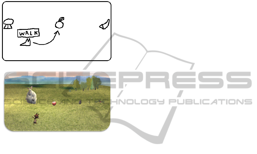
(a)
(b)
Figure 1: (a) Sample of a 2D sketch that represents our pro-
posed interface. The arrow extending from the squirrel rep-
resents movement towards the apple. The word enclosed
in the box indicates the action that the squirrel performs
while moving. (b) Initial frame of the 3D-animation result-
ing from processing the image shown in (a).
This paper is divided as follows: In Section 2 we
present present the works most related to our own ap-
proach. In Section 3 we describe the components and
intended uses of our interface, and provide examples
of its use. In Section 4 we describe the pipeline de-
veloped to implement this interface. In Section 5 we
present the results of both a performance test and a
user study of our tool. Finally, in Section 6 we present
conclusions and areas for future improvements.
2 RELATED WORK
Our work is related to previous results in the areas of
sketch-based interfaces for modeling (SBIM), sketch-
based interfaces for animation (SBIA), and sound for
animation and interaction. Results in field of SBIM
include techniques to capture sketches and recognize
a user’s intent in his or her drawings. SBIA has found
ways to describe movement by means of a sketch of
still images. Sound is an important element in any
animated film or interactive application, but is some-
times forgotten or ignored. We discuss here a classifi-
cation of sound in film and animation, ways to catego-
rize sound, and some previous results that incorporate
sound for animation or interaction.
2.1 Sketch Based Animation
There are many offline systems that can turn a sketch
into an animation. Davis et. al. (Davis et al.,
2003) developed a system where a 3D animation of
an articulated human is generated from a sequence
of sketches representing different keyframes in the
animation. Although this represents a powerful sys-
tem for the creation of animations, we decided to use
an even simpler approach for novice users, in which
symbols in a drawing depict characters and words de-
pict prerecorded animations/actions. This saves users
from the burden of describing an animation in detail.
The system in Jaewoong Jeon et. al. (Jeon et al.,
2010) allows novice users to specify the camera posi-
tion and orientation, a character’s path, and a charac-
ter’s posture by means of an input sketch that identi-
fies possible 3D poses from a database.
Masaki Oshita et. al. (Oshita and Ogiwara, 2009)
propose an interface for controlling crowds. The sys-
tem estimates a crowd’s path from a user defined
sketch. In this way, users can control a crowd’s path,
moving speed, and distance between characters. Our
approach does not consider crowds yet: every single
character and its trajectory is individually defined.
Other important approaches can be found in real
time animation systems. In Motion Doodles (Thorne
et al., 2007), users define a route for a character by
drawing a continuous sequence of lines. Arcs and
loops represent the location, timing, and types of
movement that such a character can perform.
Igarashi et. al. (Igarashi et al., 2005) show how
users can deform a 2D shape represented as a triangle
mesh. Inside such a mesh, users define and transform
control points, while the system repositions the other
vertices and minimizes distortion. All these systems
focus on manipulation of a character.
We want to allow users to create an entire scene.
Due to the focus of our research - in which we empha-
size ease of use in the creation of an animated scene
over the expressiveness of individuals characters - the
control given over a particular animation is more lim-
ited in our system than in these works.
APenandPaperInterfaceforAnimationCreation
365
2.2 Sketch Based Modeling
A variety of real time constructive systems have been
developed that enable the creation of 3D models given
2D sketches. Igarashi et. al. (Igarashi et al., 2007)
describe a system to create 3D models from 2D con-
tours. Since a 2D sketch is naturally ambiguous in
3D, such systems have complex heuristics for trans-
forming 2D into 3D.
Karpenko et. al. (Karpenko and Hughes, 2006)
propose a system that is able to reconstruct a 3D
model from 2D drawings. In their method, a user
draws some lines that correspond to a model’s out-
line and their system infers hidden contours and cre-
ates a smooth, solid 3D shape from them. In (Nealen
et al., 2007; Rivers et al., 2010; Lipson and Shpi-
talni, 1995; Lipson and Shpitalni, 2007), user-drawn
strokes are applied to a 3D model surface and serve as
handles for controlling geometry deformations. Users
can easily add, remove or deform these control curves
as if working with a 2D drawing directly. While those
systems reconstruct 3D models from detailed strokes,
our system uses shapes to retrieve 3D models from a
database; i.e. 3D models and 2D strokes do not need
to have similar shapes.
In methods proposed by Lee and Funkhouser (Lee
and Funkhouser, 2008) and Yoon and Kuijper (Yoon
and Kuijper, 2011) users draw sketches to retrieve 3D
models from a database. Our work uses a similar con-
cept to retrieve objects from a database, although we
retrieve complete models and animations, instead of
just model parts. In addition, the symbols in our sys-
tem are very simple and abstract representations of
the 3D characters and their actions.
2.3 Sound for Animation and
Interaction
There have been several works that incorporate sound
into sketch based interfaces. Chiang et. al. (Chiang
et al., 2012) create an interface that reproduces musi-
cal notes from user defined strokes. Lee et. al. (Lee
et al., 2008) present a pen that recognizes strokes and
reproduces prerecorded sounds. Although the ques-
tion of how users can control sound in an animation is
an interesting one, we decided to implicitly incorpo-
rate sound into the animations and the overall gener-
ated scene, with no particular control from the user’s
point of view. This approach keeps our interface as
simple as possible, while at the same time enabling
the creation of interesting animations complete with
sound. Future work will study ways to explicitly de-
scribe sound elements in a scene.
3 INTERFACE DESCRIPTION
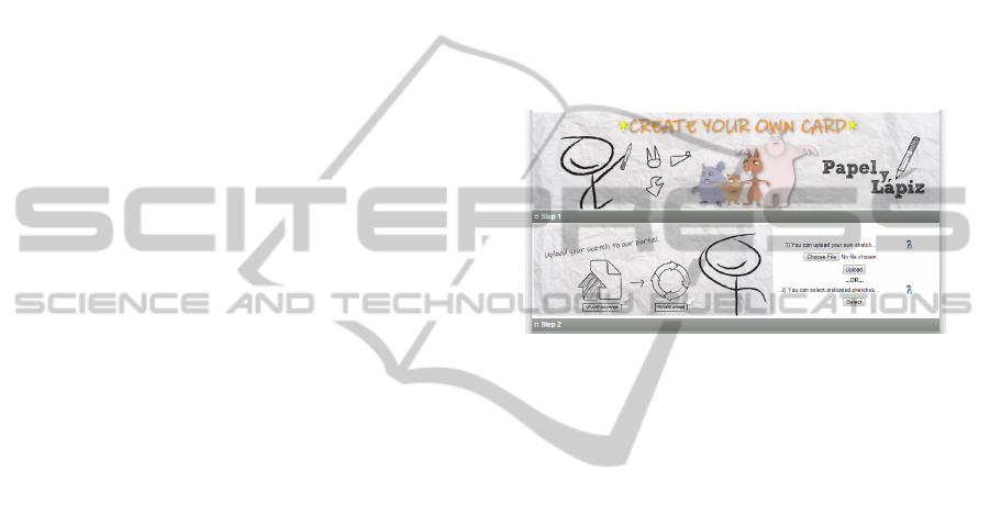
Figure 2 shows the interface of our system (Rodriguez
et al., 2013). First, we ask users to either upload a new
scanned sketch into our system or select a previously
uploaded sketch. Our system then shows a still pre-
view in which a user can see the overall composition
from the position of the camera, complete with pre-
defined scenery and the characters identified by the
system. If a user is satisfied with such a composition,
he or she can ask our system to generate the entire
animation. In that case our system asks for an email
address in order to send a link to the final animation
file.
Figure 2: Web Interface of our Tool for Animation.
Three types of elements can be drawn in a sketch:
object symbols, actions, and arrows. Object symbols
represent 3D characters in a scene, actions are words
that identify a particular animation for a 3D charac-
ter, and arrows describe paths that characters should
follow in the animation. Predefined sounds are as-
sociated with the scene, 3D characters, and their an-
imations - as we will describe in Section 4.3 - and
are automatically added to the animation without any
particular input at the sketch level.
Some restrictions should be taken into account
while drawing:
1. None of the symbols may overlap with others.
2. An object symbol must have at most one arrow.
3. An object symbol must have at most one hand-
written word.
4. Handwritten words must be spelled in uppercase,
and surrounded by a rectangle.
5. The composition must be drawn on plain white
paper without grid lines or other designs.
3.1 Object Symbols
Object symbols are abstract representations of 3D
characters in the scene. They are simple shapes that
convey some resemblance to the 3D character they
represent. Their main purpose is to identify a par-
ticular 3D character in a scene in a desired position.
GRAPP2014-InternationalConferenceonComputerGraphicsTheoryandApplications
366
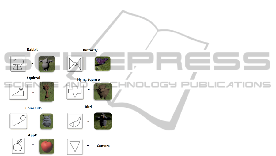
Current object symbols and their corresponding 3D
objects can be seen in Figure 3. These symbols were
chosen with the following guidelines in mind:
• Symbols should be as simple as possible for ease
of drawing;
• Symbols should be meaningful for users to reduce
the time spent looking up symbol associations;
• Symbols must be sufficiently different from one
another to facilitate the symbol recognition pro-
cess, and
• We consider a box to be a reserved symbol for the
purpose of enclosing text for actions (see WALK
in Figure 1a). Such a symbol can not be used for
other purposes.
Figure 3: Object Symbols and their corresponding 3D ob-
jects.
Object symbols can be drawn anywhere in a
sketch, and they can be used as frequently as de-
sired. Consequently, the amount of object symbols
in a sketch is only limited by practical considerations
such as the size of the paper and computer memory.
3.2 Actions
Describing an action in a simple sketch can be a chal-
lenging task (e.g. drawing a sketch for jumping). In
order to support novice users we decided to prerecord
several animations for each 3D character, and use
simple words such as ”RUN”, ”JUMP”, or ”WALK”
to execute such animations. In order to associate an
action with an object within a scene, the name of the
action must be enclosed within a box next to the ob-
ject (see Figure 1(a)). Proximity is used to associate
action with object symbols in the scene.
There is also a default action defined for each ob-
ject symbol. In this way, if there are no specific ac-
tions in a scene, a default animation will be selected
for each 3D character.
3.3 Arrows
An arrow represents a movement path for a 3D char-
acter. The 3D character closest to an arrow’s tail is
associated with the described movement, and it will
follow such a path in an orientation tangent to the ar-
row. Since sketches are drawn from above, an arrow
specifies the XZ movement of a 3D character, while
the Y component is determined by the ground, cur-
rently a plane.
4 SYSTEM IMPLEMENTATION
DETAILS
Our system performs the following four tasks in order
to generate a new animation from an input sketch: in-
put denoising, segmentation and interpretation, sound
generation, and animation generation. Input denois-
ing cleans as many artifacts from the scanned sketch
as possible. Those artifacts come from the scanning
process or from the original sketch. In the segmenta-
tion and interpretation task, our system separates ele-
ments in a sketch so they can be matched against pre-
defined symbols. Once elements are separated, our
system identifies them as object symbols, actions, or
arrows. Sound generation enriches the interpretation
of a scene with all the sound elements that such a
scene might have. Finally, animation generation deals
with the creation of both an initial screenshot and the
entire final animation.
The details of each task are described in the fol-
lowing subsections.
4.1 Input Denoising
Once a drawing is made on paper, it must be trans-
formed into a digital image and passed into our sys-
tem. This transformation can be made, for instance,
by scanning the paper sheet or capturing it through
a camera. However, these capturing processes could
create noise that could affect the segmentation of el-
ements in a sketch, such as paper imperfections or
problems with color balance. To deal with common
noise issues our system applies a filter to remove
small objects (15x15 pixels or less). Our system then
scales the image’s histogram, in order to better handle
too dark or too light images. Then it applies a mean
filter on the processed image, thus removing some of
the noise. Finally it applies a threshold filter using
APenandPaperInterfaceforAnimationCreation
367

Otsu’s method (Otsu, 1979). We have found that al-
though there are still some noise artifacts in the im-
ages after applying these filters, the remaining noise
artifacts are filtered out as unrecognized objects by
the pattern recognition algorithm thus the generated
animation is not affected.
4.2 Segmentation and Interpretation
After constructing a gray-scale, nearly noise-free im-
age, our system proceeds to extract connected com-
ponents and assign a unique label to each one. We
first separate all boxes and the components we find
inside them, which we assume to be words. Our sys-
tem then attempts to match each component against
the predefined symbols in Figure 3 using the Angle
Quantization Algorithm (Olsen et al., 2007). If a com-
ponent does not match any object symbol, our system
determines whether or not it is an arrow. These tech-
niques are described in further detail within the fol-
lowing subsections.
4.2.1 Box and Object Recognition
In order to recognize object symbols from the set of
all components, the angle quantization technique pro-
posed by Olsen et. al. (Olsen et al., 2007) was imple-
mented using k = 16 bins. As per the work’s sugges-
tion, one-pixel thinning and point tracker filters are
applied before using Angle Quantization. Boxes are
treated similarly to any other symbol, but they are
recognized first so that the text inside them may be
filtered from the composition. Such text is handled
differently from other symbols.
The segmentation of a drawing into different ele-
ments makes the angle quantization algorithm more
accurate. As a result, the comparison metric (Eu-
clidean distance) between two features becomes more
precise, allowing the use of an experimental metric as
low as 0.02 in order to identify two features as similar.
We compute such a comparison metric between a fea-
ture in a drawing against all symbols in our system.
The symbol with the smallest metric value is chosen
as the feature’s corresponding symbol. Elements that
do not fit this criteria fall in the set of possible arrows.
4.2.2 Words Recognition
We apply a standard OCR system to all words en-
closed in boxes, identified in the previous step. In
this implementation, Tesseract OCR (Tesseract OCR,
2011) was used. Having recognized an action’s name,
the system checks if the 3D character closest to the
surrounding rectangle has an action with that name
and then executes it in the final composition.
4.2.3 Arrows Recognition
Every object recognized as neither a word nor a 3D
character is considered a possible arrow. To deter-
mine if the object is indeed an arrow, our system
applies a thinning filter and then determines if the
thinned-object is composed of three segments, three
end-points and one intersection point as seen in Fig-
ure 1(a). Any thinned-object meeting these criteria is
recognized as an arrow and the longest segment is fol-
lowed to determine the trajectory such an arrow rep-
resents.
4.2.4 Scene Composition
Once all the symbols in an image have been identified,
all that remains is to generate an animation from those
symbols. For this, our system places the 3D charac-
ters in their initial position according to the objects’
position in the sketch. Information regarding the path
(arrow) and animation (action) the 3D character must
perform are now processed.
If the camera symbol is present in the composi-
tion, our system determines the initial camera’s posi-
tion and orientation from the one present in the sketch.
If the camera symbol is not present in the sketch, we
compute the bounding box of all 3D characters in the
scene and then we position the camera according to
the following heuristics:
• The camera’s X coordinate position is located in
the middle of the bounding box.
• The camera’s Y coordinate position is located at
4 units, which corresponds to the tallest character
in our scene, and with an inclination of 15 degrees
below horizontal.
• The camera’s Z coordinate position is located in
the middle of the bounding box, minus a fixed and
experimental offset value (12.0) to move the cam-
era away from the actors. In this way, the camera
captures a good portion of the scene.
It has to be noted that the coordinate system in
considers the Y axis to point up and the Z axis to point
towards the screen, in a left handed system. We also
define the entire scene to be 16 units wide (in X) and 8
units deep (in Z). Our system generates an XML file
describing the identified elements within the scene,
for readability and loose coupling to our animation
system. This file contains all the symbols that were
recognized by the system, the paths they follow and
the actions they should perform. This constructed file
acts as the input for subsequent phases in the system’s
pipeline.
GRAPP2014-InternationalConferenceonComputerGraphicsTheoryandApplications
368

4.3 Sound Generation
Sound generation in our system is achieved by a com-
bination of predefined elements, algorithms that en-
rich a scene, and the use of existing tools. Besides
a basic scene, 3D characters, and their animations,
our system takes as input a set of prerecorded sounds
classified as one of the following three types: environ-
ment sounds, voices, and Foley effects. We associate
these elements to other elements in our system: the
environment sounds to our scene, voices to particular
animations of our 3D characters, and Foley effects to
the scene and particular animations. Particular care
is taken in the timing for voices and Foley effects so
they emphasize the action in their corresponding ani-
mations.
After all 3D characters and their animations are
identified in the scene interpretation and composi-
tion stage, we execute a basic algorithm that creates
a score of all corresponding sounds in the scene by
traversing the scene elements and identifying sounds
and timing constraints. We use FFMpeg (Bellard,
2012) and Sound Exchange (SoX) (Bagwell and
Klauer, 2013) in order to prepare sounds for the fi-
nal composition, i.e. creating a long version from a
loop sound in the background. The result is an en-
riched XML file that instantiates sounds for particular
animations, including play times for such sounds.
4.4 Animation Generation
We developed a Python script in Blender (Blender
Foundation, 2011; Python Software Foundation,
2013) that reads an XML script file and generates a
3D animation. Blender uses information contained
in the XML file to appropriately configure the cam-
era, load the characters’ 3D models in their speci-
fied positions, and associate animations and sounds.
Since a composition is drawn from a top-down per-
spective and our scene’s ground is currently flat, all
the elements are placed in the XZ plane, leaving the
Y component at 0 (Y representing the height). All
3D characters are initially oriented towards the cam-
era, except for those characters that have trajectories,
which are oriented towards their direction of move-
ment. This is accomplished by calculating the angle
between the current position and the next point in a
path, and updating a character’s direction. This cal-
culation is performed along the trajectory of move-
ment, and is embedded within the XML file. Finally,
a Python script in Blender reads the score produced in
the previous stage and incorporates sound effects into
the final animation.
5 RESULTS
We performed a performance test and two user stud-
ies on our system. Our performance test measures
the rate of errors in our pattern recognition system.
Our first user study compares the ease of use between
our system and traditional methods for animation cre-
ation. Our second user study examines the effect of
sound on the users’ acceptance of the animation.
5.1 Pattern Recognition Accuracy
To test the accuracy of our current implementation,
we recruited 15 students in our University to perform
a stress test. The average age of these users was 29.6,
ranging from 18 to 37 (three undergraduate students
and twelve graduate students). They were asked to
draw three of the nine symbols, five times each, with
differences in size but not in orientation. Examples of
such drawings are shown in Figure 4. We balanced the
number of sample sheets drawn for each symbol such
that we received 5 different sample sheets per sym-
bol. We then proceeded to scan the papers in order
to test our recognition software with a consolidated
database of 225 repetitions in total. None of the stu-
dents claimed to have difficulties while drawing these
symbols. To assess the accuracy of our system we
took each one of the 225 symbols and asked our sys-
tem to identify it. The average image size used as
input was 2700 x 2200 pixels. Figure 5 shows the
number of successfully and unsuccessfully identified
symbols, categorized by symbol. 50% of the unsuc-
cessfully identified symbols were recognized as an-
other symbol whereas the other 50% went totally un-
recognized. The main sources of errors in this process
were gaps between lines in a symbol, but further stud-
ies have to be developed in order to fully characterize
these errors. We can observe that the most problem-
atic symbol is the bird, but with a success rate of 76%
we consider it good enough. Overall, we have a suc-
cess rate of 84% in the identification of symbols.
(a) (b)
Figure 4: Test drawings made by a graduate student on
(Only two sheets are shown) different sheets of paper. Our
proposed symbol of a Chinchilla (a) and Butterfly (b) was
drawn 5 times at different scales of size throughout the
whole space using only a pen.
APenandPaperInterfaceforAnimationCreation
369
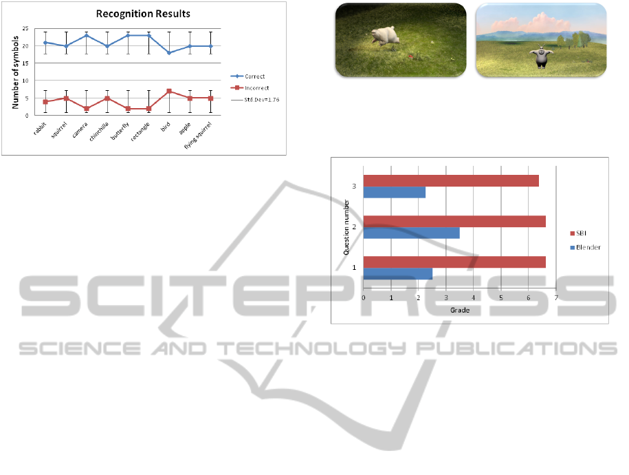
Figure 5: Recognition results for all symbols. Approxi-
mately 21 out of 25 symbols are recognized correctly with
our system.
5.2 User Study: Blender vs
Sketch-based Interfaces (SBI)
In order to test how convenient and straightforward
our system is, we performed a user study that com-
pares it versus a guided creation process in a conven-
tional animation tool. We recruited 8 students from
our University, seven undergraduate and one gradu-
ate student. The average age of these users was 21.1,
ranging from 18 to 32. Six out eight had never heard
of our SBI system. Subjects were asked if they hap-
pen to know Blender, and only one of them answered
affirmatively. Only three people had made an anima-
tion using a computer with Flash, and they claimed to
have spent at least 4 months in order to learn how to
use it. We asked our participants to create a 3D anima-
tion, both with our system and with Blender. Before
each trial subjects received a short tutorial on how to
use the tool. In the particular case of Blender, we de-
veloped a step by step video that showed subjects how
to perform the task. The Blender test consisted of ex-
ploring the files in the Big Buck Bunny movie, then
creating a snapshot of the Bunny on top of a ground
as seen in Figure 6 (a). In the SBI test we encouraged
the students to draw our Bunny symbol and upload
it to our web-based tool, in order to create a similar
snapshot (Figure 6(b)). After each trial we asked sub-
jects to answer some questions regarding the creation
process in that tool. We counter balanced the use of
our system and Blender in order to minimize possible
bias due to order of exposition.
We asked subjects to evaluate the difficulty (on a
scale from 1 to 7: 1 being difficult, 7 being easy) in
producing an animation (question 1), using the soft-
ware as a whole (q.2), and loading characters (q.3).
Figure 7 shows the results for both our tool (SBI) and
Blender. In general our system was considered easier
than the Blender based process.
At the end we asked subjects what was the most
difficult part of creating an animation with Blender.
(a) (b)
Figure 6: (a) Snapshot of an image produced following the
tutorial for Blender. (b) Snapshot of an image produced
following the tutorial for our SBI system.
Figure 7: Results from questionnaires.
Most of them said that there were too many steps and
they were not easy to follow. Finally, all eight subjects
agreed that the rabbit symbol was quite easy to draw.
5.3 User Study: Sound
The sound generation evaluation was performed by
presenting two different videos to a group of 18 peo-
ple that were asked to answer 3 questions related to
the characteristics of sound. The first video was gen-
erated with the SBI tool without any sound and the
second one was composed with the sound genera-
tion system. We asked participants if (1) the sounds
matched the scene, if (2) sound helped them better
understand the scene, and if (3) they prefer the scene
with or without sound. After results were gathered,
there was some evidence that people prefer to watch
these animations with sound, because it helps them
focus on the story and the scene.
6 CONCLUSIONS AND FUTURE
WORK
We have presented a tool that allows non expert users
to create animations by drawing a simple scene on
a sheet of paper. Users create a composition on pa-
per, scan the composition, and our system creates
a corresponding animation with basic sound effects.
We leverage 3D characters from the Big Buck Bunny
open movie in Blender, so our compositions look pro-
GRAPP2014-InternationalConferenceonComputerGraphicsTheoryandApplications
370

fessional despite the basic information given by users.
Tests we have performed in our system evidence an
84% success rate in symbol recognition, and a good
level of acceptance from our users.
Future work will focus on enriching the input vo-
cabulary in order to express timing constraints, differ-
ent background scenarios, and special sound effects.
We would also like to facilitate the creation of more
complex stories, and integrate this tool into the pro-
duction lines of other types of digital media.
ACKNOWLEDGEMENTS
This project was funded by COLCIENCIAS of
Colombia and supported in part by GRAND Network
of Centre of Excellence of Canada. We thank Troy
Alderson for editorial comments.
REFERENCES
Autodesk (2011). Maya. http://usa.autodesk.com/
maya/.
Bagwell, C. and Klauer, U. (2013). Sox - sound exchange.
http://sox.sourceforge.net/.
Bellard, F. (2012). Ffmpeg. http://ffmpeg.org/.
Blender Foundation (2008). BigBuckBunny’s Production
Files. http://graphicall.org/bbb/index.php.
Blender Foundation (2011). Blender. http://www.
blender.org/.
Chiang, C.-W., Chiu, S.-C., Dharma, A. A. G., and Tomi-
matsu, K. (2012). Birds on paper: an alternative in-
terface to compose music by utilizing sketch drawing
and mobile device. pages 201–204.
Davis, J., Agrawala, M., Chuang, E., Popovi
´
c, Z., and
Salesin, D. (2003). A sketching interface for artic-
ulated figure animation. In Proceedings of the 2003
ACM SIGGRAPH/Eurographics symposium on Com-
puter animation, SCA ’03, pages 320–328, Aire-la-
Ville, Switzerland, Switzerland. Eurographics Asso-
ciation.
Igarashi, T., Matsuoka, S., and Tanaka, H. (2007). Teddy: a
sketching interface for 3d freeform design. In ACM
SIGGRAPH 2007 courses, SIGGRAPH ’07, New
York, NY, USA. ACM.
Igarashi, T., Moscovich, T., and Hughes, J. (2005). As-
rigid-as-possible shape manipulation. In ACM SIG-
GRAPH 2005 Papers, SIGGRAPH ’05, pages 1134–
1141, New York, NY, USA. ACM.
Jeon, J., Jang, H., Lim, S.-B., and Choy, Y.-C. (2010). A
sketch interface to empower novices to create 3d an-
imations. Comput. Animat. Virtual Worlds, 21:423–
432.
Karpenko, O. A. and Hughes, J. F. (2006). Smooths-
ketch: 3d free-form shapes from complex sketches.
In ACM SIGGRAPH 2006 Papers, SIGGRAPH ’06,
pages 589–598, New York, NY, USA. ACM.
Lee, J. and Funkhouser, T. (2008). Sketch-based search and
composition of 3d models. In Proceedings of the Fifth
Eurographics conference on Sketch-Based Interfaces
and Modeling, SBM’08, pages 97–104, Aire-la-Ville,
Switzerland, Switzerland. Eurographics Association.
Lee, W., de Silva, R., Peterson, E. J., Calfee, R. C., and Sta-
hovich, T. F. (2008). Newton’s pen: A pen-based tu-
toring system for statics. Comput. Graph., 32(5):511–
524.
Lipson, H. and Shpitalni, M. (1995). A new interface of
conceptual design based on object reconstruction from
a single freehand sketch. In Annals of the CIRP Vol.
44/1, Annals of the CIRP Vol. 44/1, pages 133–136,
New York, NY, USA. ACM.
Lipson, H. and Shpitalni, M. (2007). Optimization-based
reconstruction of a 3d object from a single freehand
line drawing. In ACM SIGGRAPH 2007 courses, SIG-
GRAPH ’07, New York, NY, USA. ACM.
Nealen, A., Igarashi, T., Sorkine, O., and Alexa, M.
(2007). Fibermesh: designing freeform surfaces with
3d curves. In ACM SIGGRAPH 2007 papers, SIG-
GRAPH ’07, New York, NY, USA. ACM.
Olsen, L., Samavati, F. F., and Sousa, M. C. (2007). Fast
stroke matching by angle quantization. In Proceedings
of the First International Conference on Immersive
Telecommunications, ImmersCom ’07, pages 6:1–6:6,
ICST, Brussels, Belgium, Belgium. ICST (Institute for
Computer Sciences, Social-Informatics and Telecom-
munications Engineering).
Oshita, M. and Ogiwara, Y. (2009). Sketch-based interface
for crowd animation. pages 253–262.
Otsu, N. (1979). A Threshold Selection Method from Gray-
level Histograms. IEEE Transactions on Systems,
Man and Cybernetics, 9(1):62–66.
Python Software Foundation (2013). Python. http://www.
python.org/.
Rivers, A., Durand, F., and Igarashi, T. (2010). 3d modeling
with silhouettes. In ACM SIGGRAPH 2010 papers,
SIGGRAPH ’10, pages 109:1–109:8, New York, NY,
USA. ACM.
Rodriguez, D., Figueroa, P., and Arcos, J. (2013).
SBI for Animation for Non-Experts. http:
//papelylapiz.virtual.uniandes.edu.co/
pyl5/www/cgi-bin/inicio.pl.
Tesseract OCR (2011). Tesseract OCR. http://code.
google.com/p/tesseract-ocr/.
Thorne, M., Burke, D., and van de Panne, M. (2007). Mo-
tion doodles: an interface for sketching character mo-
tion. In ACM SIGGRAPH 2007 courses, SIGGRAPH
’07, New York, NY, USA. ACM.
Ulano, M. (2012). The movies are born a child of the
phonograph. http://www.filmsound.org/ulano/
talkies2.htm/.
Wilches, D., Figueroa, P., Conde, A., and Samavati, F.
(2012). Sketch-based interface for animation for non-
experts. In Informatica (CLEI), 2012 XXXVIII Con-
ferencia Latinoamericana En, pages 1–8.
Yoon, S. and Kuijper, A. (2011). Sketch-based 3d model re-
trieval using compressive sensing classification. Elec-
tronics Letters, 47(21):1181–1183.
APenandPaperInterfaceforAnimationCreation
371
