
Automated Composition of Sequence Diagrams via Alloy
Mohammed Alwanain
1
, Behzad Bordbar
1
and Juliana K. F. Bowles
2
1
School of Computer Science, University of Birmingham, Birmingham, U.K.
2
School of Computer Science, University of St Andrews, St Andrews, Scotland
Keywords:
UML Sequence Diagrams, Model Transformation, Composition, Alloy.
Abstract:
Design of large systems often involves the creation of models that describe partial specifications. Model com-
position is the process of combining partial models to create a single coherent model. This paper presents an
automatic composition technique for creating a sequence diagram from partial specifications captured in mul-
tiple sequence diagrams with the help of Alloy. Our contribution is twofold: a novel true-concurrent semantics
for sequence diagram composition, and a model-driven transformation of sequence diagrams onto Alloy that
preserves the semantics of composition defined. We have created a tool called SD2Alloy that implements the
automated technique and works as follows: two given sequence diagrams are transformed in two Alloy mod-
els, and then combined according to a set of logical constraints, determined by our compositional semantics,
into a final composed Alloy model. The technique can also be used to detect problems and inconsistencies in
the composition of diagrams.
1 INTRODUCTION
The process of developing modern systems is grad-
ually becoming more and more complex. Due to
the increase in the complexity of software develop-
ment processes, we often make use of multiple mod-
els for expressing various scenarios and viewpoints.
To reduce the complexity of the design, models of the
system are usually broken into partial specifications.
For example, behaviour related to the interaction be-
tween parts can be captured by different sequence di-
agrams. However, integrating these diagrams into one
to describe the whole behaviour requires model com-
position techniques. Manual model composition is
error-prone, time-consuming and tedious (Rosa et al.,
2010). In recent years, automated model composi-
tion has received considerable attention (Rubin et al.,
2008; Widl et al., 2013). For example (Rubin et al.,
2008) make use of Alloy for automated composition.
Nonetheless, most automated merging methods only
focus on static representation.
In this paper we deal with automated integra-
tion of sequence diagrams, one of UML’s behavioural
models. In particular, we focus on the composition of
sequence diagrams with the help of Alloy. Our con-
tribution is twofold: a novel true-concurrent seman-
tics for sequence diagram composition, and a model-
driven transformation of sequence diagrams onto Al-
loy that preserves the semantics of composition.
Our automated technique follows three main
steps. In the first step, multiple sequence diagrams
are automatically transformed into Alloy models. For
each sequence diagram a unique Alloy model is pro-
duced which if solved has as many solutions as pos-
sible execution traces in the original sequence dia-
gram. The execution traces are the ones obtained in
the underlying semantics of sequence diagrams used
(K
¨
uster-Filipe, 2006). The semantics is defined over
the true-concurrent model of labelled event structures
(LES) (Winskel and Nielsen, 1995).
In the second step, the Alloy models are merged
to produce a single Alloy model, which contains ele-
ments from the Alloy model of the sequence diagrams
in addition to logical constraints specifying how the
sequence diagrams should be composed. Here the
logical constraints are derived in accordance to our
defined true-concurrent semantics of composition. In
the third step, we use the single model to formally
check if sequence diagrams can be composed and
to work out the composition of the sequence dia-
grams automatically. These steps are fully automated
with our tool SD2Alloy which was implemented us-
ing Model Driven Architecture (MDA) techniques
(Kleppe et al., 2003). Later in the paper, we justify
further our choice of Alloy is a target language.
The remainder of the paper is structured as fol-
384
Alwanain M., Bordbar B. and K. F. Bowles J..
Automated Composition of Sequence Diagrams via Alloy.
DOI: 10.5220/0004715003840391
In Proceedings of the 2nd International Conference on Model-Driven Engineering and Software Development (MODELSWARD-2014), pages 384-391
ISBN: 978-989-758-007-9
Copyright
c
2014 SCITEPRESS (Science and Technology Publications, Lda.)

lows: Section 2 gives a general background of se-
quence diagrams, their formalisation with event struc-
tures and Alloy. Section 3 addresses model compo-
sition syntactically (at the UML level) and semanti-
cally (over labelled event structures) which guides the
model transformation from sequence diagrams onto
Alloy as discussed in Section 4. Section 5 describes
model composition via Alloy, whereas Section 6 out-
lines our tool. Finally, Section 7 describes related
work and Section 8 concludes the paper.
2 BACKGROUND
2.1 Sequence Diagrams
UML sequence diagrams capture scenarios of execu-
tion as object (or in some cases component) interac-
tions. Each object has a vertical dashed line called
lifeline showing the existence of the object at a par-
ticular time. Points along the lifeline are called loca-
tions (a terminology borrowed from LSCs (Harel and
Marelly, 2003)) and denote the occurrence of events.
The order of locations along a lifeline is significant
denoting, in general, the order in which the corre-
sponding events occur.
A message is a synchronous or asynchronous
communication between two objects shown as an ar-
row connecting the respective lifelines, that is, the
underlying send and receive events of the message.
We only cover synchronous communication in this
paper. An interaction between several objects con-
sists of one or more messages, but may be given fur-
ther structure through so-called interaction fragments.
There are several kinds of interaction fragments in-
cluding seq (sequential behaviour), alt (alternative
behaviour), par (parallel behaviour), neg (forbidden
behaviour), assert (mandatory behaviour), loop (iter-
ative behaviour), and so on (OMG, 2011). Depending
on the operator used, an interaction fragment consists
of one or more operands. In the case of the alt frag-
ment, each operand describes a choice of behaviour.
Only one of the alternative operands is executed if
the guard expression (if present) evaluates to true. If
more than one operand has a guard that evaluates to
true, one of the operands is selected nondeterministi-
cally for execution. In the case of the par fragment,
there is a parallel merge between the behaviours of
the operands. The event occurrences of the differ-
ent operands can be interleaved in any way as long
as the ordering imposed by each operand as such is
preserved.
Finally, interaction fragments can be nested pro-
ducing expressive and complex scenarios of execu-
tion. One simple example illustrating the concepts
above and with a parallel nested within an alterna-
tive fragment is given in Figure 1. In this case, all
l4
sd 3
a:A
b:B
m3
m4
m1
l0
l1
l2
l5
l6
l7
l8
l9
alt
m2
par
l3
Figure 1: A sequence diagram with nested fragments.
messages (from m
1
to m
4
) are sent synchronously be-
tween objects a and b. The locations along the life-
line of object a are shown explicitly. The importance
of locations as well as the effect produced through the
nesting of fragments (i.e., the possible traces of exe-
cution) are described in the next subsection. In par-
ticular, the distinction between the syntactic notion of
a location on a sequence diagram from its semantic
counterpart of an event will be clarified.
2.2 Formal Model
Several possible semantics for sequence diagrams
have been defined (see (Micskei and Waeselynck,
2011) for an overview). In this paper we use the se-
mantics defined in (K
¨
uster-Filipe, 2006) which intro-
duces a very simple and intuitive behavioural model
to capture interactions, and is the only true-concurrent
semantics available for sequence diagrams.
Prime event structures (Winskel and Nielsen,
1995), or event structures for short, describe dis-
tributed computations as event occurrences together
with binary relations for expressing causal depen-
dency (called causality) and nondeterminism (called
conflict). The causality relation implies a (partial) or-
der among event occurrences, while the conflict rela-
tion expresses how the occurrence of certain events
excludes the occurrence of others. From the two re-
lations defined on the set of events, a further relation
is derived, namely the concurrency relation co. Two
events are concurrent if and only if they are com-
pletely unrelated, i.e., neither related by causality nor
by conflict.
Formally, an event structure is a triple E =
(Ev, →
∗
, #) where Ev is a set of events and →
∗
, # ⊆
Ev ×Ev are binary relations called causality and con-
flict, respectively. Causality →
∗
is a partial order.
AutomatedCompositionofSequenceDiagramsviaAlloy
385

Conflict # is symmetric and irreflexive, and propa-
gates over causality, i.e., e#e
0
→
∗
e
00
⇒ e#e
00
for all
e, e
0
, e
00
∈ Ev. Two events e, e
0
∈ Ev are concurrent,
e co e
0
iff ¬(e →
∗
e
0
∨ e
0
→
∗
e ∨ e#e
0
).
We omit further technical details on the model, but
note that for the application of event structures as a
semantic model for sequence diagrams we use dis-
crete event structures. Discreteness imposes a finite-
ness constraint on the model, i.e., there are always
only a finite number of causally related predecessors
to an event, known as the local configuration of the
event. A further motivation for this constraint is given
by the fact that every execution has a starting point or
configuration.
Event structures are enriched with a labelling
function (usually a total function µ : Ev → L that maps
each event onto an element of the set L). This la-
belling function is necessary to establish a connection
between the semantic model (event structure) and the
syntactic model (here a sequence diagram).
Intuitively, each location marked along a lifeline
of an object in a sequence diagram corresponds to one
(possibly more) event(s) in the labelled event struc-
ture. The set of labels used could be the set of loca-
tions in a sequence diagram but is usually more con-
crete information on what the location represents: the
initialisation of an object, sending/receiving a mes-
sage, beginning/ending an interaction fragment, etc.
Consider the locations marked on Figure 1 for ob-
ject a. The events in the model shown in Figure 2 have
a direct correspondence to the locations of object a.
(m4,r)
e0
e1
e3
e2
(m1,s)
(m2,s)
e4
e5
e6
e7
e82
e81
(m3,r)
#
Figure 2: Event structure for object a of Figure 1.
The graphical representation of the event structure
E
a
shows immediate causality between events (e.g.,
e
0
→ e
1
) and direct conflict (e.g., e
2
#e
3
). By conflict
propagation we also have e
2
#e
4
, etc. Unrelated events
are concurrent (e.g., e
5
co e
6
). Intuitively, events e
1
and e
4
denote the beginning of the alternative and par-
allel fragments respectively. Consequently events e
5
(denoting the receipt of message m
3
) and e
6
(denoting
the receipt of message m
4
) are concurrent. Events e
81
and e
82
both correspond to location l
8
denoting the
end of the alternative fragment. These events must
be in conflict because they represent different ways
to reach the location. Note that there cannot be one
end event in this case, because conflict propagates
over causality and it would lead to an event in conflict
with itself and hence an invalid event structure (con-
flict is irreflexive). Some event labels are given where
(m
1
, s) denotes sending message m
1
, and (m
3
, r) de-
notes receiving message m
3
.
Let I denote the set of objects involved in the inter-
action described by sequence diagram SD. A model
M
SD
= (E, µ) for a sequence diagram SD is obtained
by composition of the models M
i
= (E
i
, µ
i
) of each
object instance i ∈ I. In the composed model, the set
of events Ev is such that e ∈ Ev iff there is an ob-
ject i ∈ I such that e ∈ Ev
i
, or (e
1
, e
2
) ∈ Ev iff there
are two objects i 6= j ∈ I with e
1
∈ Ev
i
, e
2
∈ Ev
j
,
µ
i
(e
1
) = (m, s) and µ
j
(e
2
) = (m, r). In other words,
shared events (e
1
, e
2
) correspond to message synchro-
nisation. To keep it simple, we assume that µ : Ev →
Mes is a partial function defined over shared events
only and indicating the message exchanged. I.e.,
µ(e
1
, e
2
) = m iff µ
i
(e
1
) = (m, s) and µ
j
(e
2
) = (m, r)
for some i, j ∈ I. More details on the semantics of se-
quence diagrams using event structures can be found
in (K
¨
uster-Filipe, 2006).
2.3 Alloy
Alloy (Jackson, 2006) is a declarative textual mod-
eling language based on first-order relational logic.
An Alloy model consists of a number of signature
declarations, fields, facts and predicates. Further-
more, each signature denotes a set of atoms, which
are the basic entities of Alloy. Alloy is supported by
a fully automated constraint solver called Alloy Ana-
lyzer, which permits the analysis of system properties
by searching for instances of the model. It is possi-
ble to check whether certain properties of the system
are present. This is achieved via an automated trans-
lation of the model into a Boolean expression, which
is then analysed by SAT solvers such as SAT4 (Berre
and Parrain, 2010) embedded within the Alloy Ana-
lyzer. The Alloy Analyzer has been used in various
applications including the composition of static mod-
els (Rubin et al., 2008).
In this paper, Alloy is used as part of an automated
tool to compose sequence diagrams. The composition
is based on a set of logical constraints which we desig-
nate merging glue. Alloy is a language for describing
the structural information underlying a design model
whereas labelled event structures are needed to make
sure the semantics of the behavioural model and the
MODELSWARD2014-InternationalConferenceonModel-DrivenEngineeringandSoftwareDevelopment
386

composition are as expected.
The choice of Alloy as a target framework is a
natural one. Alloy makes it straightforward to find a
model (if available) for the composition of sequence
diagrams. The approach converts each sequence di-
agram into a set of logical constraints to which it
is simple to add additional constraints capturing the
merging glue. Alloy solves these constraints to find a
model that complies to both sequence diagrams and
the glue.
3 MODEL COMPOSITION
For the integration of two or more scenarios we define
syntactic composition of sequence diagrams and its
underlying semantics.
Our mechanism for composition of sequence dia-
grams considers interleaving of diagrams and shared
behaviour. In the first case, diagrams evolve com-
pletely autonomously whereas in the latter case di-
agrams have shared behaviour (shared objects and
messages). We treat the cases separately and consider
only the composition of two diagrams. The case for
an arbitrary number of diagrams is easily generalised
from here. In the sequel, let SD
1
and SD
2
be two se-
quence diagrams, with sets of instances and messages
given by I
1
, I
2
, Mes
1
and Mes
2
respectively.
The interleaving of diagrams SD
1
and SD
2
with
Mes
1
∩ Mes
2
=
/
0 is written SD
1
k SD
2
and is defined
syntactically as par(SD
1
, SD
2
). In other words, it
consists of a diagram with a par fragment and two
operands where each operand contains the behaviour
described in SD
1
and SD
2
respectively.
Semantically, the model for SD
1
k SD
2
is an event
structure M
SD
1
kSD
2
= (E, µ) where Ev = Ev
1
∪ Ev
2
,
all relations are preserved, and µ(e) is defined for all
e iff µ
i
(e) is defined for some i ∈ {1, 2} in which case
µ(e) = µ
i
(e). For shared instances o ∈ I
1
∩ I
2
we fur-
ther match the initial and maximal events in Ev
1
and
Ev
2
. We illustrate this with an example (see Figure 3)
showing shared objects but different messages.
m2
a:A
l2
l1
l0
sd 1
b:B
m1
a:A
p2
p1
p0
sd 2
b:B
Figure 3: Two simple sequence diagrams.
The models associated to SD
1
and SD
2
are given
in Figure 4.
As described above, if we compose both models
we can merge initial and maximal events for shared
objects which in this case corresponds to events e
a0
m1
ea0’
ea2’
eb2’
eb0’
(ea1’,eb1’)
m2
ea0
ea2
eb2
eb0
(ea1,eb1)
Figure 4: Model for SD
1
(left) and SD
2
(right).
and e
a0
0
, e
b0
and e
b0
0
, e
a2
and e
a2
0
, and e
b2
and e
b2
0
.
The final composition SD
1
k SD
2
is shown in Figure 5.
eb0
ea0
ea2
(ea1,eb1)
m1
(ea1’,eb1’)
m2
eb2
Figure 5: Model for SD
1
k SD
2
.
This is the exact model obtained for a sequence
diagram which consists of a parallel fragment with
two operands where the first operand is taken from
SD1 and the second operand is taken from SD
2
.
The composition of diagrams SD
1
and SD
2
with
shared behaviour is written SD
1
k
G
SD
2
where G =
Mes
1
∩ Mes
2
indicates the shared behaviour.
If G = Mes
1
, in other words, all the behaviour in
SD
1
is shared, then we say that SD
1
is syntactically
contained in SD
2
, and the composition SD
1
k
G
SD
2
can be reduced to SD
2
.
We now consider the case that G = {m}. This case
can be generalised to a finite number of messages, but
we omit it here for simplicity.
Consider SD
1
= seq(ϕ
0
, m, ϕ
1
) and SD
2
=
seq(ϕ
0
0
, m, ϕ
1
0
) where seq denotes a sequential
fragment, ϕ
0
, ϕ
1
, ϕ
0
0
and ϕ
1
0
are interactions
which on their own would define a valid se-
quence diagram and may be empty. The com-
position SD
1
k
G
SD
2
is defined syntactically by
seq(par(ϕ
0
, ϕ
0
0
), m, par(ϕ
1
, ϕ
1
0
)).
Note that the seq fragment describes the default
(sequential) behaviour of a sequence diagram and can
be omitted in a diagram, but is useful here to describe
composition in general. For example, SD
1
from Fig-
ure 3 can be seen as seq(ϕ
0
, m
1
, ϕ
1
) with ϕ
0
and ϕ
1
both empty.
Consider a more complex case where SD
1
=
f (seq(ϕ
0
, m, ϕ
1
), ϕ
2
) and SD
2
= seq(ϕ
0
0
, m, ϕ
1
0
)
where f denotes an arbitrary fragment (e.g., par, alt,
etc). The composition SD
1
k
G
SD
2
is defined syntacti-
cally by f (seq(par(ϕ
0
, ϕ
0
0
), m, par(ϕ
1
, ϕ
1
0
)), ϕ
2
). In
other words, if the shared behaviour is contained in an
arbitrary fragment, then this fragment is preserved in
the composed behaviour.
Consider the sequence diagrams SD
1
and SD
2
AutomatedCompositionofSequenceDiagramsviaAlloy
387
given in Figure 6 which share message m
2
.
m4
b:B
alt
m1
m2
m3
sd 1
a:A
a:A
sd 2
b:B
m2
Figure 6: Two sequence diagrams with shared message m
2
.
The sequence diagrams can be seen as SD
1
=
alt(ϕ
0
, seq(
/
0, m2, ϕ
1
)) and SD
2
= seq(
/
0, m2, ϕ
1
0
)),
with ϕ
0
corresponding to a simple interaction
with m
1
, and similarly for ϕ
1
and message
m
3
, and ϕ
1
0
and message m
4
. The composi-
tion SD
1
k
G
SD
2
as outlined above is given by
alt(ϕ
0
, seq(
/
0, m
2
, par(ϕ
1
, ϕ
1
0
))). The composed dia-
gram is our first sequence diagram from Figure 1.
Given the syntactic composition of two sequence
diagrams we derive the model (a labelled event struc-
ture) as described before.
4 MODEL TRANSFORMATION
TO ALLOY
We implement our composition method with the help
of MDA techniques (Kleppe et al., 2003). Due to
space restrictions, we only discuss the transformation
rules in this paper. These rules can be implemented
via any MDA transformation engine. We now give an
overview of the transformation rules from sequence
diagrams to Alloy. Our approach is such that if an Al-
loy model can be solved, it generates all possible solu-
tions each of which corresponds to a run of the orig-
inal sequence diagram and in accordance to the for-
mal semantics defined in the previous sections. Three
transformation rules are defined and described below.
4.1 Lifeline and Message
Each lifeline in a sequence diagram, which corre-
sponds to an object with a name and type (class), must
be transformed into Alloy code.
1 abstract sig Lifeline {}
2 one sig A{} //lifeline Class
3 one sig a {} //Lifeline name
4 one sig Lifeline_1 extends Lifeline {
5 name: a,
6 type: A }
The code above shows an example of a lifeline
declaration in Alloy. In line 1, abstract sig rep-
resents the definition of an abstract signature for
Lifeline which can then be extended later by con-
crete lifelines from a sequence diagram. Line 4 gives
a concrete lifeline declaration Lifeline 1. The key-
word one in the declaration indicates that there is ex-
actly one instance of the signature. Furthermore, a
lifeline signature has two fields: name to specify the
object name, and type to specify its class.
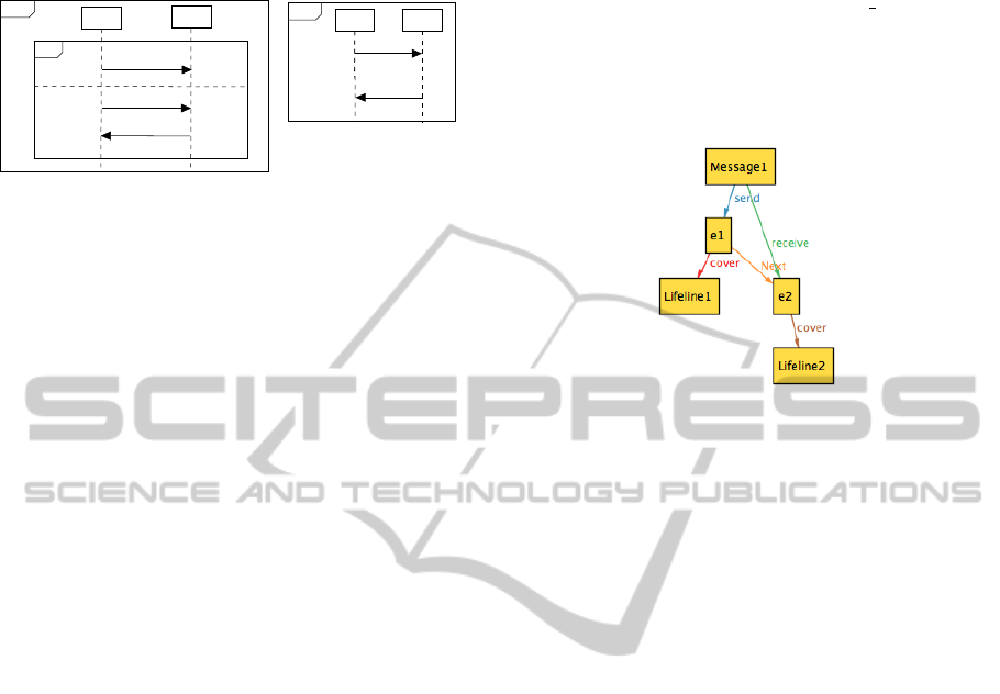
Figure 7: Message representation in an Alloy instance.
The transformation of a message into Alloy code
maps the message components (message name and
corresponding send and receive events) to corre-
sponding signatures in Alloy also making appropriate
connections to the lifelines of the sender and receiver
objects (see Figure 7).
In the code, the transformation creates an abstract
signature Message which consists of a send and re-
ceive Event, also a defined abstract signature. In our
example, events e1 and e2 are declared in lines 7-
10. Additionally, for each message we need to de-
fine the order of occurrence of its respective send
and receive events. In Alloy, this is given by a logi-
cal constraint fact messageEventsOrder, which in
this case specifies that for all messages, the send event
always happens before the receive event.
1 abstract sig Event {NEXT :set Event}
2 abstract sig Message{send: Event,
3 receive: Event}
4 one sig M1{} //Message name
5 one sig message extends Message{
6 NAME: M1,} //Message declaration
7 one sig e1 extends Event{
8 COVER: Lifeline_1} //Event declaration
9 one sig e2 extends Event{
10 COVER: Lifeline_2}
//assigning events to their message
11 fact {
12 e1 in message.send
13 e2 in message.receive
//message send before receive
14 fact messageEventOrder{
15 all M: Message| M.receive in M. send.NEXT}
In general, a sequence diagram contains several
messages. In case of a basic sequence diagram with-
out interaction fragments, this implies a total order
MODELSWARD2014-InternationalConferenceonModel-DrivenEngineeringandSoftwareDevelopment
388

along the events of the lifeline of an object. This
is specified in Alloy by another logical constraint
called fact generalOrder which specifies the or-
der in which all messages and their underlying events
occur along the lifelines of the corresponding object
instances.
//general order
fact generalOrder {
e2 in e1.NEXT
e4 in e3.NEXT}
In the example above, the fact specifies that e2
occurs after e1 (it is in a relation NEXT with e1), and
e4 occurs after e3. Nothing is said about the relation
between e2 and e4.
4.2 Parallel Combined Fragment
For the parallel interaction fragment (also called com-
bined fragment in accordance to the UML metamodel
(OMG, 2011)), the transformation generates a set of
abstract signatures as can be seen in lines 1-3 of the
code fragment below.
1 abstract sig Combinedfragment {
2 cover:set Operand}
3 abstract sig Operand{cover:set Event}
4 one sig CF_TYPE_PAR{}//Combinedfragment Type
5 one sig CF extends Combinedfragment{
6 TYPE = CF_TYPE_PAR}
7 one sig Operand_1 extends Operand{}
8 one sig Operand_2 extends Operand{}
// Covering: Combined Fragment->Operands
9 fact{
10 Operand_1 in CF.cover
11 Operand_2 in CF.cover}
.............
12 fact{all CF: Combinedfragment,
13 OP1: CF.cover, OP2: CF.cover,
14 E1: OP1.cover,E2: OP2.cover,
15 E3: OP1.cover |
16 no E4: OP2.cover | OP1 != OP2
17 and E2 in E1.NEXT
18 and E3 in E4.NEXT }
Each of these abstract signatures represents the
main elements in the metamodel of the combined
fragment. sig CF TYPE PAR in line 4 declares the
type of the combined fragment, in this case a PAR. Fol-
lowing this, in lines 7 and 8, two signatures define the
number of operands used, in this case Operand 1 and
Operand 2. The fact in line 9 connects the parallel
fragment with its operands. Each operand covers the
send and receive events of the messages defined inside
it. Finally, the Alloy model that contains a parallel
combined fragment must show a parallel execution of
operand 1 and operand 2, in other words, the events
covered by each operand are not related by NEXT and
can thus occur in an arbitrary order. This is given in
the fact of line 12, and is in accordance to the labelled
event structure semantics given earlier. It implies a
relation of concurrency between events in different
operands whilst the events within an operand remain
ordered in the usual way. Therefore, this fact guaran-
tees the preservation of the correct and intended order
of events in a parallel fragment.
4.3 Alternative Combined Fragment
In Alloy code, the representation of an alternative
combined fragment is similar to that of a parallel com-
bined fragment with an additional constraint to pre-
serve the semantics as can be seen below.
// alt: exact one operand will be executed
fact{all CF: Combinedfragment |
( CF.TYPE = CF_TYPE_ALT) => # CF.cover = 1}
The fact above defines that at most one operand
is executed. This implies that a different set of events
occurs for each possible run of the code.
5 COMPOSITION VIA ALLOY
In order to compose Alloy models that have been
obtained by transformation from sequence diagrams,
two fundamental conditions must be satisfied:
• Matching elements must indicate correspondence
between equivalent elements of the source. The
purpose of matching is to uncover how two mod-
els correspond to each other.
• Merging of equivalent elements identified earlier
producing a composed version of the models.
In Alloy, these conditions can be encoded by
adding facts that must be satisfied to match and merge
equivalent elements. For example, consider two Al-
loy models A1 and A2 each with two lifelines, where
these lifelines have the same name and type. In or-
der to compose the lifelines with the same name from
each one of the models we have to specify the fact
below.
fact lifelineEquality {
all L1: A1_Lifeline_1 , L2: A2_lifeline_1 |
(L1.type=L2.type && L1.name=L2.name) =># L2=0}
The Alloy code above shows that if the matching
condition is satisfied, then lifelines will be merged
into one which is L1 (andL2 will be hidden). The
same is true of messages. For example, if the two Al-
loy models A1 and A2 have two messages, and these
messages have the same name, send and receive from
the same lifelines, then Alloy will compose these
messages into one.
AutomatedCompositionofSequenceDiagramsviaAlloy
389
The idea of the procedure of merging entered
models in Alloy is as follows. First we generate a new
Alloy model A3 representing the result of merging the
original models. Second, we copy all the elements of
A1 to A3. Third, we copy all elements of A2 except
the duplication elements such as abstract signatures
that are shared in the two models. Fourth, for any pair
of equal elements, one of the signatures keyword has
to be changed from one to lone to be able to merge it
and then add the merging facts mentioned above. Fi-
nally, in terms of merging messages, the merged mes-
sage events (send and receive) are replaced with their
equivalent message events to apply the behaviour en-
vironment of both models into this message.
To validate our approach, we implemented the ex-
ample of Figure 6 in Alloy. After solving the merged
model, we obtained three Alloy solutions (also re-
ferred to as instances). These instances show ex-
actly the expected behaviour underlying Figure 1 with
possible traces of execution: only m1 occurs, or
m2 · (m3 co m4) occur.
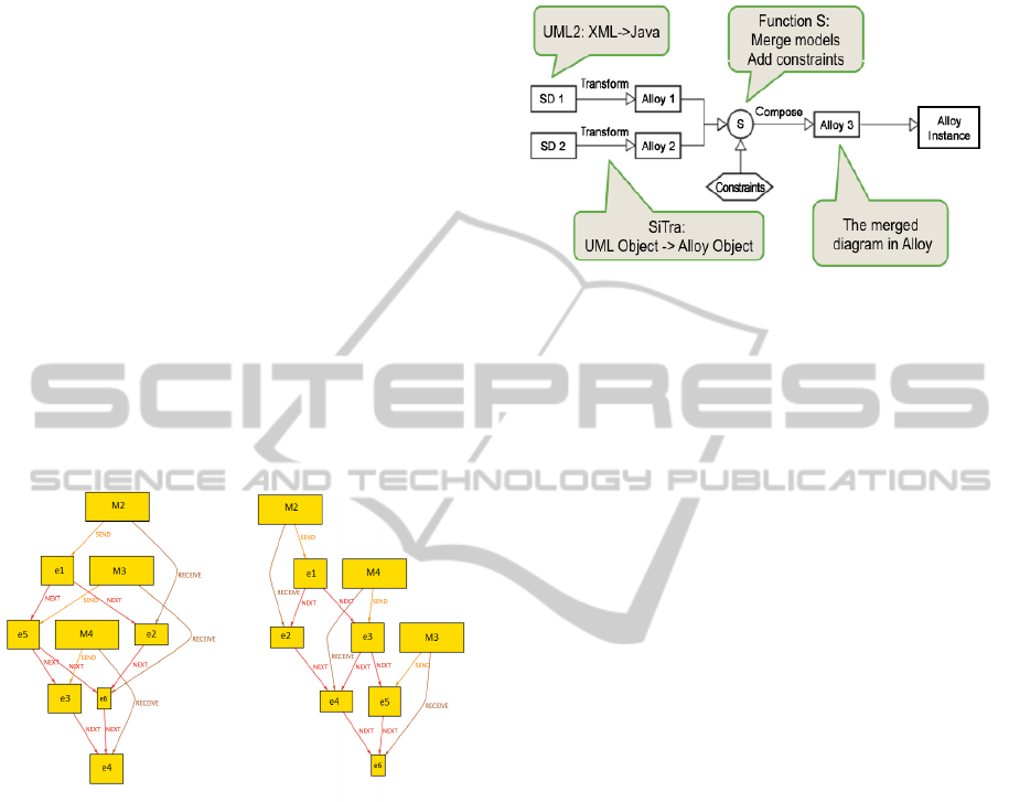
Figure 8: Alloy instance of merging the diagrams from Fig-
ure 6.
Figure 8 shows two Alloy instances, one for each
of the possible executions of the second operand of
the alternative fragment. These instances show in par-
ticular that m
2
is always before m3 and m4, and m3
and m4 are in parallel.
We have recently developed an Eclipse plugin
called SD2Alloy which implements the above ap-
proach. The tool uses MDA (Kleppe et al., 2003)
to transform two sequence diagrams and combine
them as depicted in Figure 9. The figure outlines
the SD2Alloy architecture. The tool parses XMI files
exported from the UML tool Papyrus(Lanusse et al.,
2009) into sequence diagram Java objects using the
UML2 library. SiTra (Akehurst et al., 2006) is used
to transform the Java objects of sequence diagrams
and create the Alloy Java object that produces the Al-
loy code. Moreover, this tool allows the user to spec-
ify composition constraints (merging glue) required
in Alloy to merge the entered models.
Figure 9: The SD2Alloy architecture.
6 RELATED WORK
Over the last decade, a number of software tools and
algorithms have been designed and implemented to
compose behavioural models. (Liang et al., 2008),
have presented a method of integrating sequence di-
agrams based on the formalisation of sequence di-
agrams as typed graphs. (Rubin et al., 2008), il-
lustrate the use of the Alloy Analyzer to compose
class diagrams based on syntactic properties of meta-
models and the primary model. This approach uses
UML2Alloy (Anastasakis, K et al., 2007) to trans-
form UML class diagrams into Alloy and Alloy An-
alyzer to compose these classes. However, their
method only composes static models and the compo-
sitional code produced is generated manually.
In addition, (Widl et al., 2013) present an ap-
proach for composing concurrently evolved sequence
diagrams in accordance to the behaviour given in state
machine models. They describe the problem of merg-
ing sequence diagrams formally using SAT solvers.
However, similarly to (Liang et al., 2008), the ap-
proach does not merge complex sequence diagrams.
When looking at the integration of several model
views or diagrams, (K
¨
uster-Filipe and Bordbar, 2007)
present a method of mapping a design consisting of
class diagrams, OCL constraints and sequence dia-
grams into a mathematical model for detecting and
analysing inconsistencies. Finally, (Ara
´
ujo et al.,
2004) propose a further approach to composition of
sequence diagrams by composing sequence diagram
operators directly. This approach is very different
from ours and can be seen as a high-level composi-
tion strategy at the UML level.
MODELSWARD2014-InternationalConferenceonModel-DrivenEngineeringandSoftwareDevelopment
390

7 CONCLUSIONS
In this paper, we have defined a new compositional
semantics of sequence diagrams based on the true-
concurrent model of labelled event structures, and
presented an automated technique based on Alloy that
relies on the true-concurrent semantics.
The underlying developed tool takes as an input
one or more sequence diagrams, and automatically
constructs Alloy solutions for the composition. Each
of the solutions corresponds to a run that can be
derived from the underlying labelled event structure
of the composed sequence diagram. Our approach
has been evaluated through a series of examples and
larger case studies.
The composition as defined in this paper assumes
a diagram as representing possible but not mandatory
behaviour. It is our intention to extend this view to
a more flexible approach which enables designers to
choose between must and may interactions. An exten-
sion of our formal framework and consequent trans-
lation to Alloy to cover both options is subject to fur-
ther work, as is an extension to more complex features
from sequence diagrams in Alloy.
REFERENCES
Akehurst, D., Bordbar, B., Evans, M., Howells, W., and
McDonald-Maier, K. (2006). SiTra: Simple transfor-
mations in Java. In MoDELS’06, LNCS 4199, pages
351–364. Springer.
Ara
´
ujo, J., Whittle, J., and Kim, D. (2004). Modeling and
composing scenario-based requirements with aspects.
In RE 2004, pages 58–67. IEEE.
Berre, D. L. and Parrain, A. (2010). The SAT4j library,
release 2.2 - system description. Journal on Satisfia-
bility, Boolean Modeling and Computation, 7:59–64.
Anastasakis, K., Bordbar, B., Georg, G., and Ray, I. (2007).
UML2Alloy: A challenging model transformation. In
Model Driven Engineering Languages and Systems,
pages 436–450. Springer.
Harel, D. and Marelly, R. (2003). Come, Let’s Play:
Scenario-based Programming Using LSCs and the
Play-Engine. Springer.
Jackson, D. (2006). Software Abstractions: logic, language
and analysis. MIT Press.
Kleppe, A., Warmer, J., and Bast, W. (2003). MDA Ex-
plained: The model driven architecture: practice and
promise. Addison-Wesley.
K
¨
uster-Filipe, J. (2006). Modelling concurrent interactions.
Theoretical Computer Science, 351:203–220.
K
¨
uster-Filipe, J. and Bordbar, B. (2007). A formal model
for integrating multiple views. In ACSD 2007, pages
71–79. IEEE.
Lanusse, A., Tanguy, Y., Espinoza, H., Mraidha, C., Ger-
ard, S., Tessier, P., Schnekenburger, R., Dubois, H.,
and Terrier, F. (2009). Papyrus UML: an open source
toolset for MDA. In ECMDA-FA 2009, pages 1–4.
Liang, H., Diskin, Z., Dingel, J., and Posse, E. (2008). A
general approach for scenario integration. In MoD-
ELS’08, LNCS 5301, pages 204–218. Springer.
Micskei, Z. and Waeselynck, H. (2011). The many mean-
ings of UML 2 sequence diagrams: a survey. Software
and Systems Modeling, 10:489–514.
OMG (2011). UML: Superstructure. Version 2.4.1. OMG,
http://www.omg.org. Document id: formal/2011-08-
06. [accessed 1-6-2012].
Rosa, M. L., Dumas, M., Uba, R., and Dijkman, R. (2010).
Merging business process models. On the Move to
Meaningful Internet Systems: OTM 2010, pages 96–
113.
Rubin, J., Chechik, M., and Easterbrook, S. (2008). Declar-
ative approach for model composition. In MiSE’08,
pages 7–14. ACM.
Widl, M., Biere, A., Brosch, P., Egly, U., Heule, M., Kap-
pel, G., Seidl, M., and Tompits, H. (2013). Guided
merging of sequence diagrams. In SLE 2012, LNCS
7745, pages 164–183. Springer.
Winskel, G. and Nielsen, M. (1995). Models for Concur-
rency. In Abramsky, S., Gabbay, D., and Maibaum,
T., editors, Handbook of Logic in Computer Science,
Vol. 4, Semantic Modelling, pages 1–148. Oxford Sci-
ence Publications.
AutomatedCompositionofSequenceDiagramsviaAlloy
391
