
Performance Analysis of Random Relaying of Partitioned MDS
Codeword Block Applied to Persistent Relay CSMA
over Random Error Channels
Katsumi Sakakibara and Jumpei Taketsugu
Department of Information and Communication Engineering, Okayama Prefectural University, 719-1197, Soja, Japan
Keywords:
Cooperative Multi-hop Networks, Markov Model, MDS Codes, Performance Analysis, Persistent Relay
CSMA.
Abstract:
We propose incorporation of Random relaying of Partitioned Maximum Distance Separable codeword blocks
(RP-MDS), which has been proposed for multi-hop cooperative relay networks, to Persistent Relay Carrier
Sense Multiple Access (PRCSMA) over noisy channels. The proposed protocol elaborately employs the pow-
erful error-correcting capability of MDS codes into cooperative communication systems and introduces the
incremental redundancy concept to PRCSMA. A destination node can reinforce an error-correcting capability
when it receives a new frame. The performance of the proposed protocol is analyzed with a Markov model in
terms of the average duration of a cooperation phase and the energy efficiency. Numerical results indicate that
the proposed protocol can significantly improve the performance, compared to the original PRCSMA.
1 INTRODUCTION
Cooperative communications with relay nodes have
been recognized as one of effective and promising
techniques in wireless/mobile communication sys-
tems. Relay standards are on the way to suc-
cessful implementation in Long Term Evolution
(LTE)-Advanced by the Third Generation Partner-
ship Project (3GPP) and 802.16m by IEEE (Loa
et al., 2010; Bhamri et al., 2011). Relay tech-
niques have been enthusiastically investigated from
the viewpointof the physical (PHY) and data-link lay-
ers (Bhamri et al., 2011; G´omez-Cuba et al., 2012). In
PHY layer perspective, Multiple-Input and Multiple-
Output (MIMO) and diversity techniques are attrac-
tive. In the data-link layer perspective, a number
of Cooperative Automatic Repeat reQuest (C-ARQ)
protocols have been proposed and analyzed. Partic-
ularly, the design of Medium Access Control (MAC)
protocols employed between relay nodes and the des-
tination node influences the performance, when two
or more relay nodes collaborate on an identical chan-
nel.
MAC protocols for C-ARQ systems have been
proposed recently. Dianati et al. (Dianati et al.,
2006) proposed a Node-Cooperation Stop-and-Wait
(NCSW) ARQ protocol. The performance of NCSW
with a single relay node was analyzed over two-
state Markovian channels. Morillo and Garcia-Vidal
(Morillo and Garcia-Vidal, 2011) proposed a C-ARQ
scheme with an integrated frame combiner. They
analyzed the performance with round-robin cooper-
ation among relay nodes and with Carrier Sense Mul-
tiple Access with Collision Avoidance (CSMA/CA).
Alonso-Zarate et al. (Alonso-Zarate et al., 2009;
Predojev et al., 2012) proposed Persistent Relay
CSMA (PRCSMA), which elaborately incorporates
well-known IEEE 802.11 Distributed Coordination
Function (DCF) (IEEE Standard 802.11, 1999). In
(Alonso-Zarateet al., 2009), the performance of PRC-
SMA was analyzed based on a steady-state two-
dimensional Markovian model proposed by Bianchi
(Bianchi, 2000). In the above literature (Dianati et al.,
2006; Morillo and Garcia-Vidal, 2011; Alonso-Zarate
et al., 2009; Predojev et al., 2012), it is basically as-
sumed that a node can correctly receive a transmitted
frame if no frame collisions occur. Thus, when we
consider a scenario where a channel adds errors to
a non-colliding frame, it is expected that the use of
error-correcting codes can improve the performance.
In this paper, we propose incorporation of Ran-
dom relaying of Partitioned Maximum Distance Sep-
arable codeword block (RP-MDS) (Sakakibara et al.,
2011) to PRCSMA over noisy channels. The pro-
155
Sakakibara K. and Taketsugu J..
Performance Analysis of Random Relaying of Partitioned MDS Codeword Block Applied to Persistent Relay CSMA over Random Error Channels.
DOI: 10.5220/0004708501550164
In Proceedings of the 3rd International Conference on Sensor Networks (SENSORNETS-2014), pages 155-164
ISBN: 978-989-758-001-7
Copyright
c
2014 SCITEPRESS (Science and Technology Publications, Lda.)

S D
Source node Destination node
SER =
1
R
2
R
N
R
ε
SD
Relay nodes
:
:
ε
SR
1
ε
SR
2
ε
SR
n
ε
R D
2
ε
R D
n
ε
R D
1
Figure 1: System model with N relay nodes.
posed protocol elaborately takes advantage of the
powerful error-correcting capability of MDS codes.
Incorporating RP-MDS into PRCSMA may intro-
duce effective performance improvement in accor-
dance with the concept of incremental redundancy
(Pursley and Sandberg, 1989). A destination node
can reinforce an error-correcting capability when it
receives a new frame, even if it includes channel er-
rors. The performance of the proposed protocol is an-
alyzed with the aid of a Markov model. The accuracy
of the model is verified by means of computer simu-
lation.
The rest of the present paper is organized as fol-
lows: Section 2 presents a system model with relay
nodes. PRCSMA is briefly reviewed in Section 3.
In Section 4, after a short reminder of useful prop-
erties of MDS codes, the proposed protocol is de-
scribed. Performance of the proposed protocol is an-
alyzed in Section 5, based on the analysis in (Alonso-
Zarate et al., 2009). Numerical results are presented
in Section 6 in comparison with results obtained from
computer simulation. Finally, Section 7 concludes the
present paper.
2 SYSTEM MODEL
Consider a wireless network consisting of a pair of
source node S and destination node D with N relay
nodes; R
1
, R
2
,. .. , R
N
, as shown in Fig. 1. All chan-
nels are half-duplex, so that a node can not transmit
and receive simultaneously. All nodes are located
within their transmission range. Hence, each node can
overhear ongoing transmission originating from other
nodes. Let ε
SD
, ε
SR
n
, and ε
R
n
D
be the symbol error
probabilities on channels between source node S and
destination node D, between source node S and relay
node R
n
, and between relay node R
n
and destination
node D, respectively, for n = 1,2,...,N.
1
If frame
1
Using the symbol error rate ε, we can evaluate the bit
error rate as 1−
m
√
1−ε when a symbol consists of m bits.
transmission from source node S resulted in erroneous
reception at destination node D and if one or more
relay nodes succeeded in error-free reception of the
frame, then such relay nodes can collaborativelyserve
as supporters for frame retransmission. For effective
use of cooperative communications, we generally as-
sume that ε
SD
> ε
R
n
D
. The duration in which relay
nodes collaborate frame retransmissions is referred to
as a cooperation phase (Alonso-Zarate et al., 2009).
Note that every frame is assumed to include an ap-
propriate header and an ideal Frame Check Sequence
(FCS) for error/collision detection,
2
in addition to the
payload.
3 PERSISTENT RELAY CSMA
(PRCSMA)
PRCSMA (Alonso-Zarate et al., 2009; Predojevet al.,
2012) is a MAC protocol which elaborately re-
solves frame collisions among transmission from re-
lay nodes, based on IEEE 802.11 DCF (IEEE Stan-
dard 802.11, 1999). Similarly to IEEE 802.11 DCF,
each relay node in PRCSMA inserts random back-
off delay before every frame transmission in a dis-
tributed manner according to its own contention win-
dow (CW). Let m denote a message block of k-
symbol length, which is generated at source node S.
A DATA frame consists of a header, payload m, and
FCS. Note that the terms “message block m” and
“DATA frame” are used interchangeably hereafter,
unless ambiguity arises.
The operation in PRCSMA is summarized as fol-
lows. The detailed description can be found in
(Alonso-Zarate et al., 2009). After erroneous recep-
tion of a DATA frame, destination node D broadcasts
a Call For Cooperation (CFC) frame. If one or more
relay nodes receive both the DATA frame and the CFC
frame, then the cooperation phase is invoked. Relay
nodes which join in the cooperation phase is referred
to as active relay nodes. Active relay nodes simulta-
neously start the DCF operation, after the reception of
the CFC frame followed by DIFS (Distributed Inter-
Frame Space). When destination node D correctly
receives a frame, it broadcasts an ACK frame to an-
nounce not only correct reception of the DATA frame
to source node S but also completion of the coopera-
tion phase to all the nodes.
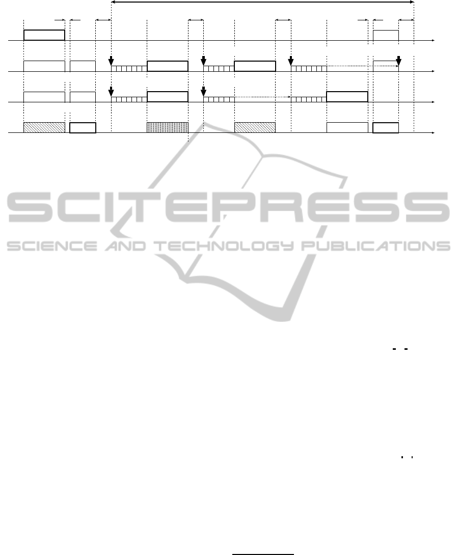
An illustrative operational example with two ac-
tive relay nodes, R
1
and R
2
, is shown in Fig. 2.
Both active relay nodes independently set their back-
2
The term “ideal” implies that the probability of unde-
tected errors can be neglected.
SENSORNETS2014-InternationalConferenceonSensorNetworks
156
S
D
R
R
1
2
start of backoff
SIFS DIFS ACKtimeout ACKtimeout SIFS DIFS
erroneous reception frame collision error-free reception
cooperation phase
CFC ACK
erroneous reception
error-free reception
error-free reception
time
time
time
time
discard of DATA
freeze
freeze
start of backoff
start of backoff
start of backoff
start of backoff
m
m
m
m
m
Figure 2: Illustrative example of PRCSMA.
off counter to seven and a cooperation phase is in-
voked. The first DATA frame transmission from these
relay nodes results in collision. The second transmis-
sion from relay node R
1
suffers from channel errors.
Finally, an ACK frame is returned by destination node
D corresponding to error-free reception of the second
transmission from R
2
. It completes the cooperation
phase. Notice that source node S does not participate
in a cooperation phase (Alonso-Zarate et al., 2009).
4 PRCSMA WITH RANDOM
RELAYING OF PARTITIONED
MDS CODEWORD BLOCK
In a cooperation phase in PRCSMA over noisy chan-
nels, destination node D may successively receive er-
roneous frames one by one in between backoff in-
tervals. It suggests possibility to effectively utilize
the concept of incremental redundancy (Pursley and
Sandberg, 1989), where the error-correcting capabil-
ity at a receiving node is reinforced upon frame re-
ception. In this context, we propose incorporating
RP-MDS into PRCSMA. RP-MDS has been proposed
for multi-hop cooperative relay networks over noisy
channels (Sakakibara et al., 2011). The proposed
protocol, designated as PRCSMA+RP-MDS, is de-
scribed after some properties of MDS codes are re-
viewed.
4.1 MDS Codes
Denote a linear block code of length n and dimension
k over a certain finite field by an [n,k] code. An [n,k]
code is MDS if its minimum distance is n −k + 1. A
class of MDS codes, including Reed-Solomon codes,
is known to be fruitful in advantageous properties
(Wicker, 1995). Among them, the following two the-
orems; Theorems 8-4 and 8-6 in (Wicker, 1995), re-
spectively, are used afterward:
Theorem 1. For an [n,k] MDS code, a receiver can
recover the encoded message of length k, if it receives
at least k code symbols with no errors.
Theorem 2. Punctured MDS codes are also MDS,
that is, the minimum distance of an [n − p,k] punc-
tured MDS code is n− p−k + 1, if n− p ≥ k.
Suppose a systematic [Lk,k] MDS code C .
3
Let
G be a generator matrix of C . It is clear that G is a
k×Lk matrix. Let
G =
I
|{z}
k
G
1
|{z}
k
G
2
|{z}
k
···
G
L−1
|
{z}
k
(1)
be a partition of G into L blocks of identical size,
where I and G
ℓ
are an identity matrix and a square
matrix of order k for ℓ = 1,2,. .. ,L −1, respectively.
Then, for a message block m of length k to be en-
coded, a codeword of C can be also partitioned into L
codeword blocks c
ℓ
of length k;
c = mG =
c
0
|{z}
k
c
1
|{z}
k
c
2
|{z}
k
···
c
L−1
|
{z}
k
, (2)
where c
0
= m and c
ℓ
= mG
ℓ
for ℓ = 1,2,...,L−1.
From Theorem 1 and Theorem 2, the following corol-
lary holds at a receiver when one or more codeword
blocks c
ℓ
are received:
Corollary 1. Assume that u distinct codeword blocks,
c
ℓ
1
, c
ℓ
2
,. .. , c
ℓ
u
, are received and that a receiver
3
Using a systematic code, an encoded message appears
explicitly in the corresponding codeword vector. It implies
that its generator matrix includes an identity matrix, as its
submatrix. In the case that a given generator matrix is non-
systematic, we can convert it into a systematic form with
the aid of appropriate elementary row operations (Peterson
and Weldon, 1972).
PerformanceAnalysisofRandomRelayingofPartitionedMDSCodewordBlockAppliedtoPersistentRelayCSMAover
RandomErrorChannels
157
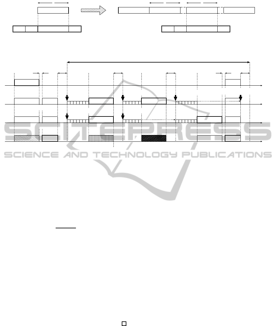
systematic MDS coding
header
DATA frame (source node S) Relayed frame (relay node R )
c
1 l -1L
c c
l
c
message m message m
k kk
n
PHY MAC message m FCS
header
PHY MAC FCS
Figure 3: Frame format.
S
D
R
R
1
2
start of backoff
SIFS DIFS ACKtimeout ACKtimeout SIFS DIFS
erroneous reception frame collision successful decoding
cooperation phase
CFC ACK
decoding failure
error-free reception
error-free reception
time
time
time
time
discard of DATA
freeze
freeze
start of backoff
start of backoff
start of backoff
start of backoff
c
1
c
2
c
1
c
3
m
Figure 4: Illustrative example of proposed protocol (PRCSMA+RP-MDS).
can identify the received codeword block number,
ℓ
1
,ℓ
2
,. .. ,ℓ
u
, for u ≤ L and 0 ≤ ℓ
1
< ℓ
2
< ··· < ℓ
u
≤
L −1. Then, a k-symbol message m can be recov-
ered, if either of the following conditions is satisfied:
(i) at least one codeword block c
ℓ
is error-free; and
(ii) the total number of errors occurred in the u code-
word blocks is less than or equal to
t
u
=
(u−1)k
2
, (3)
where ⌊x⌋ is the maximum integer not greater than x.
Proof. Since every codeword block c
ℓ
consists of k
symbols, it is straightforward from Theorem 1 that
a receiver can recover the message m from one or
more error-free codeword blocks. This leads to the
first condition.
Next, aggregation of the u distinct received code-
word blocks results in a codeword of a [uk,k] punc-
tured MDS code. Thus, t
u
or less errors can be cor-
rected according to Theorem 2, which provides the
second condition.
4.2 Proposed Protocol
(PRCSMA+RP-MDS)
In PRCSMA, as described in Section 3, what a re-
lay node transmits is a replica of the message block
m. Therefore, it is required for destination node D
to receive a frame with no errors in order to complete
the cooperation phase. By contrast, in the proposed
protocol, an active relay node randomly transmits
one out of L −1 redundant MDS codeword blocks;
c
1
,c
2
,. .. ,c
L−1
, after encoding the received message
block m by C , as in (2). Furthermore, destina-
tion node D stores erroneously received frames in the
buffer rather than discard.
A frame format used in the proposed protocol is
depicted in Fig. 3. The codeword block number ℓ
should be appropriately embedded in a header part,
which can be digitized by ⌈log
2
L⌉ bits, where ⌈x⌉ is
the minimum integer not less than x. For small L, it
can be negligible.
We describe the proposed protocol with the aid of
an illustrative operational example with the same sce-
nario as shown in Fig. 4. Destination node D stores an
erroneous message block m into its buffer. Two ac-
tive relay nodes R
1
and R
2
independently encode m
and randomly select one codeword block. In Fig. 4,
R
1
selects c
1
and R
2
selects c
2
. After frame colli-
sion occurs, each relay node re-selects one codeword
block; R
1
does c
1
again and R
2
, c
3
. Upon a recep-
tion of c
1
from relay node R
1
, destination node D
aggregates the received c
1
and the m in the buffer,
and then, decodes [ m
c
1
] by a [2k,k] punctured
MDS code of C . According to Corollary 1, the mes-
sage block m can be retrieved if c
1
is received with
no errors or if the total number of symbol errors in
[ m
c
1
] is not greater than ⌊k/2⌋ . However,it fails in
Fig. 4. At this time, destination node D stores two er-
SENSORNETS2014-InternationalConferenceonSensorNetworks
158

roneous blocks, m and c
1
. Subsequently to reception
of c
3
from R
2
, the message block m is successfully
recovered by decoding [ m
c
1
c
3
] with a [3k,k]
MDS code, which can correct up to k errors. Finally,
an ACK frame is returned from destination node D. It
completes the cooperation phase.
Notice that source node S does not take part in
a cooperation phase similarly to PRCSMA (Alonso-
Zarate et al., 2009). Furthermore, for L = 1 the pro-
posed protocol is reduced to the original PRCSMA,
since no error-correctingcapability is available at des-
tination node D.
5 PERFORMANCE ANALYSIS
5.1 Assumptions and Markov Model
In this section, we analyze the performance in the
cooperation phase, based on the Markov model in
(Alonso-Zarate et al., 2009). We impose identical as-
sumptions with (Alonso-Zarate et al., 2009). Since
we focus on the cooperation phase, it is presumed
that destination node D has stored an erroneous mes-
sage block m. We assume that a cooperation phase
start with N active relay nodes. We ignore erroneous
reception of control frames; ACK frames, and of a
header part in each frame. The CW value at each re-
lay node remains constant W all the time, that is, no
doubling procedure is carried out even if frame trans-
mission failure occurs, as opposed to the legacy DCF
(IEEE Standard 802.11, 1999). All frames involved
in collision are to be retransmitted, until the coopera-
tion phase is completed. We assume symmetric chan-
nels between relay node R
n
and destination node D,
that is, the symbol error rates between each relay node
and destination node D are identical and independent;
ε
R
1
D
= ε
R
2
D
= ··· = ε
R
N
D
= ε
RD
.
Then, a Markov model with respect to the value
of backoff counter at a relay node is quoted in Fig. 5
from (Alonso-Zarate et al., 2009). In Fig. 5, P
ec
repre-
sents the probability that the cooperation phase ends
in a slot. Note that a slot duration varies depending
on frame transmissions in the slot.
5.2 Equations in Equilibrium
In equilibrium, an in-flow and an out-flow are bal-
anced for every state in Fig. 5. Letting π
w
be
the steady-state probability of state w for w =
0,1,2, .. .,W −1, we obtain
π
w
=
π
w+1
+
1
W
π
0
+
W−1
∑
i=0
P
ec
π
i
!
for w = 0,1,2,...,W −2,
1
W
π
0
+
W−1
∑
i=0
P
ec
π
i
!
for w = W −1.
(4)
Solving the recursive expression and the boundary
condition in (4) under the normalizing condition π
0
+
π
1
+ ···+ π
W−1
= 1, we have
π
w
=
P
ec
{1−(1−P
ec
)
W−w
}
WP
ec
−(1−P
ec
){1−(1−P
ec
)
W−w
}
(5)
for w = 0,1,...,W −1. Since frame transmission oc-
curs only when the backoff counter reaches to zero,
the probability of i-frame collision can be given by
q
i
= Pr[i-frame collision] =
N
i
π
i
0
(1−π
0
)
N−i
(6)
for i = 0,1,...,N. Then, a slot is idle with probability
q
0
, one frame is transmitted in a slot with probability
q
1
, and frame collision takes place with probability
1−q
0
−q
1
.
Next, we evaluate the probability P
ec
of complet-
ing the cooperation phase. Destination node D stores
an erroneous DATA frame c
0
= m, when the coop-
eration phase starts. The initial probability that the
stored message includes e symbol errors is
α(e) =
1
1−(1−ε
SD
)
k
k
e
ε
e
SD
(1−ε
SD
)
k−e
(7)
for e = 1,2,...,k. Then, when destination node D re-
ceives a non-collided frame; say c
ℓ
, ℓ > 0 if L > 1,
aggregating two blocks results in [c
0
c
ℓ
]. The co-
operation phase ends, if either of two conditions in
Corollary 1 is satisfied. The probability of error-free
reception of a block of length k is (1−ε
RD
)
k
. Taking
into account the fact that up to ⌊k/2⌋ errors in [c
0
c
ℓ
]
can be corrected, we have the probability of success-
ful decoding at destination node D as
P
succ
=
(1−ε
RD
)
k
for L = 1,
(1−ε
RD
)
k
+
⌊k/2⌋−1
∑
j=1
⌊k/2⌋−j
∑
e=1
k
j
ε
j
RD
(1−ε
RD
)
k−j
α(e)
for L ≥ 2.
(8)
In the case of L > 2, further gain on P
succ
can be avail-
able when other code word blocks are received. How-
ever, we omit it in (8). Finally, we obtain
P
ec
= q
1
P
succ
= nπ
0
(1−π
0
)
n−1
P
succ
. (9)
PerformanceAnalysisofRandomRelayingofPartitionedMDSCodewordBlockAppliedtoPersistentRelayCSMAover
RandomErrorChannels
159

210
P
ec
P
ec
P
ec
P
ec
P
ec
1-
W-1W-2
P
ec
1-P
ec
1-P
ec
1-
W1/ W1/ W1/ W1/ W1/
+ + +
+
Figure 5: Markov model (Alonso-Zarate et al., 2009).
5.3 Average Duration of Cooperation
Phase
Once P
ec
is provided, it implies that a cooperation
phase consists of 1/P
ec
slots in average, in which the
last slot is the only successful one. Hence, the average
numbers of idle slots, of slots with 1-frame transmis-
sion, and of slots with frame collision can be evalu-
ated by
#[idle] =
1
P
ec
−1
q
0
1−q
1
P
succ
, (10)
#[1-frame transmission]
= 1 +
1
P
ec
−1
q
1
(1−P
succ
)
1−q
1
P
succ
, (11)
#[frame collision] =
1
P
ec
−1
1−q
0
−q
1
1−q
1
P
succ
, (12)
respectively. Then, the average duration of a cooper-
ation phase, given that N active relay nodes collabo-
rate, is given by
E[duration
N]
= T
succ
+ T
slot
#[idle]
+ T
fail
(#[1 frame transmission] −1
+ #[frame collision])
= T
succ
+
1
P
ec
−1
×
T
slot
q
0
+ T
fail
(1−q
0
−q
1
P
succ
)
1−q
1
P
succ
, (13)
where T
slot
, T
succ
, and T
fail
are the idle slot dura-
tion, the duration of successful message transmission
consisting of the DATA and the ACK frames, SIFS
and DIFT, and the duration of erroneous reception
or frame collision consisting of the DATA frame and
ACKtimiout, respectively. They are given as
T
succ
= T
DATA
+ T
SIFS
+ T
ACK
+ T
DIFS
, (14)
T
fail
= T
DATA
+ T
ACKtimeout
, (15)
where T
DATA
and T
ACK
are DATA frame duration and
ACK frame duration, respectively, and other T
x
’s are
the duration of element x.
5.4 Energy Efficiency in Cooperation
Phase
Similarly to (13), the average of total energy con-
sumed in a cooperation phase starting with N active
relay nodes can be evaluated;
E[energy consumption
N]
= E
succ
+ E
idle
#[idle]
+ E
fail
(1)(#[1-frame transmission] −1)
+
N
∑
i=2
E
fail
(i)#[i-frame collision]
= E
succ
+
1
P
ec
−1
1
1−q
1
P
succ
×
(
E
idle
q
0
+ E
fail
(1)q
1
(1−P
succ
)
+
N
∑
i=2
E
fail
(i)q
i
)
, (16)
where E
succ
is the total energy consumed by N active
relay nodes, source node S and destination node D in a
successful slot, E
idle
is that in an idle slot, and E
fail
(i)
is that in an unsuccessful slot, given that i-frame col-
lision occurs for i = 1,2,... ,N, respectively. Let P
T
,
P
R
, and P
S
be consumed power at a node when trans-
mitting, receiving, and sensing the channel, respec-
tively. Then, three states in (16) of the energy con-
sumption in a slot are given by
E
succ
= P
T
T
DATA
+ P
S
T
SIFS
+ P
R
T
ACK
+ P
S
T
DIFS
+ P
R
T
DATA
+ P
S
T
SIFS
+ P
T
T
ACK
+ P
S
T
DIFS
+ N(P
R
T
DATA
+ P
S
T
SIFS
+ P
R
T
ACK
+ P
S
T
DIFS
), (17)
E
idle
= (N + 2)P
S
T
slot
, (18)
E
fail
(i) = i(P
T
T
DATA
+ P
S
T
ACKtimeout
)
+ (N + 2−i)(P
R
T
DATA
+ P
S
T
ACKtimeout
)
(19)
for i = 1,2, .. .,N, respectively. Finally, we define the
energy efficiency η as
η =
E[message length in bits]
E[energy consumption
N]
(20)
for a cooperation phase starting with N active relay
nodes.
SENSORNETS2014-InternationalConferenceonSensorNetworks
160

Table 1: Parameters for numerical results.
(a) Frame format
PHY preamble 96 [µsec]
MAC header (incl. FCS)
34 [byte]
message length 512 [byte]
ACK length
14 [byte]
CFC length
14 [byte]
Block length: k 64 [symbol]
(b) DCF parameters
slot duration: T
slot
10 [µsec]
DIFS: T
DIFS
50 [µsec]
SIFS: T
SIFS
10 [µsec]
ACKtimeout: T
ACKtimeout
50 [µsec]
CW: W 16
(c) Power
Transmission P
T
1900 [mW]
Reception P
R
1340 [mW]
Channel sensing P
S
1340 [mW]
(d) Channel
channel rate (DATA) 54 [Mbps]
channel rate (control)
6 [Mbps]
symbol error rate:
(10
−1
,10
−2
)
(ε
SD
,ε
RD
)
(10
−2
,10
−3
)
6 NUMERICAL RESULTS
We examine the derived expressions with exhaustive
computer simulation and compare the performance of
the proposed protocol to that of PRCSMA. The val-
ues of parameters employed are shown in Table 1.
The frame format and the DCF parameters are basi-
cally extracted from (Alonso-Zarate et al., 2009; Pre-
dojev et al., 2012) and IEEE 802.11 standard (IEEE
Standard 802.11, 1999). The power consumption is
identical with (Predojev et al., 2012). Two pairs of
the symbol error rates are considered; (ε
SD
,ε
RD
) =
(10
−1
,10
−2
) and (10
−2
,10
−3
). A block length in
frame is k = 64 symbols and two types of MDS codes
C are considered; a half-rate [128,64] MDS code for
L = 2, a quarter-rate [256,64] MDS code for L = 4.
Note that for L = 2, a relay node always transmits c
1
,
since a codeword consists of two blocks; c = [c
0
=
m
c
1
]. The theoretical results for L = 4 are omitted
in order to avoid the complexity to derive the prob-
ability of successful decoding at destination node D,
(8). The simulation program is written in C language
and the results are obtained by averaging 10
5
trials of
cooperation phases. Recall that a cooperation phase
starts with destination node D which has already held
m including e errors with probability α(e), (7), for
e = 1,2,...,k.
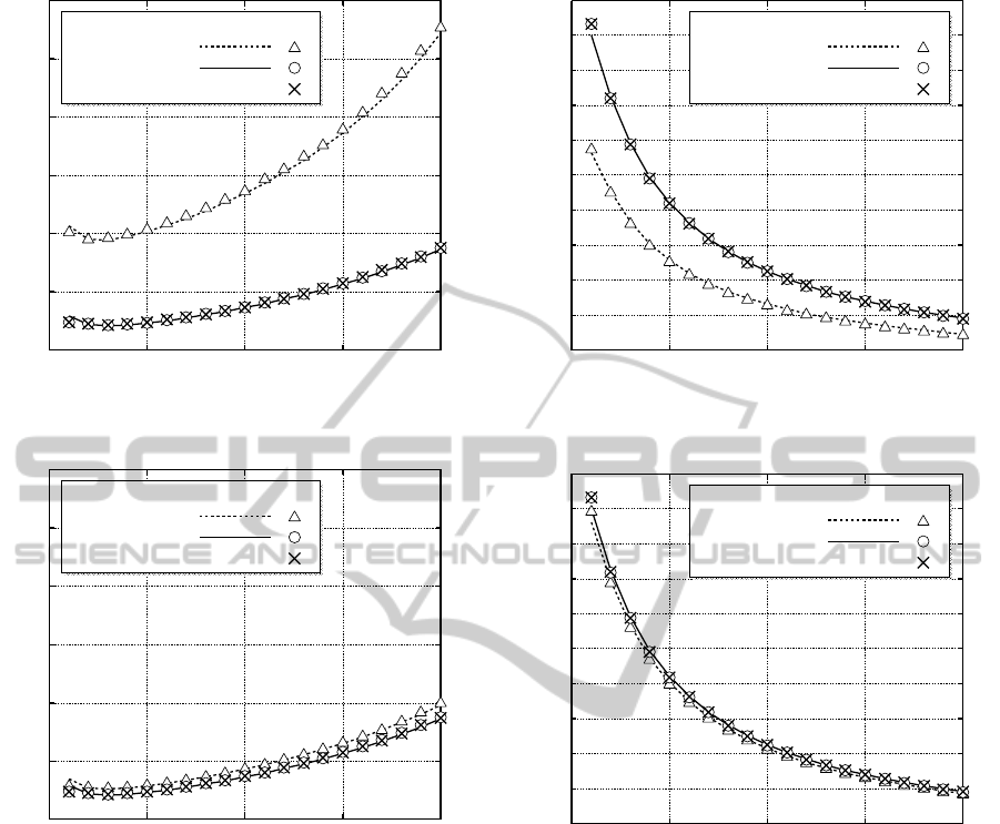
The average duration of a cooperation phase
and the energy efficiency in a cooperation phase
are presented in Fig. 6 and in Fig. 7, respectively,
as a function of the number of active relay nodes
N. The agreement between the theoretical and
simulation results validates the accuracy of the de-
rived expressions. Evidently, the proposed protocol,
PRCSMA+RP-MDS, outperforms the original PRC-
SMA. In addition, it is revealed from computer sim-
ulation that the performance of PRCSMA+RP-MDS
for L = 4 coincides with that for L = 2, so that a half-
rate MDS code suffices for PRCSMA+RP-MDS.
From Fig. 6(a) the proposed protocol can achieve
approximately 40% reduction in the average duration
of a cooperation phase for (ε
SD
,ε
RD
) = (10
−1
,10
−2
).
The Energy efficiency is also improved by the pro-
posed protocol, as shown in Fig. 7(a). However, it
is clear from Fig. 6(b) and Fig. 7(b) that the degree
of performance improvement by the proposed pro-
tocol decreases, as the channel quality is enhanced,
since the opportunity to take advantage of the error-
correcting capability of the MDS code decreases at
destination node D. For the values of parameters
given in Table 1, the probability of error-free recep-
tion of a frame is
(1−ε
RD
)
k
≈
(
0.526 for ε
RD
= 10
−2
,
0.938 for ε
RD
= 10
−3
.
(21)
It implies that destination node D requires to re-
ceive a frame approximately 1/0.526 ≈ 1.90 times
and 1/0.938 ≈ 1.07 times in average before the mes-
sage m be successfully recovered for ε
RD
= 10
−2
and
ε
RD
= 10
−3
, respectively. On the other hand, since
destination node D can receive a frame other than m
in the cooperation phase in the proposed protocol, the
error-correcting decoding for a half-rate [2k,k] MDS
code can be carried out. In this case, at most ⌊k/2⌋
symbol errors can be corrected. Then, the probability
of decoding failure is given as
2k
∑
i=⌊k/2⌋+1
2k
i
ε
i
RD
(1−ε
RD
)
2k−i
≈
(
1.70×10
−36
for ε
RD
= 10
−2
,
3.92×10
−96
for ε
RD
= 10
−3
,
(22)
PerformanceAnalysisofRandomRelayingofPartitionedMDSCodewordBlockAppliedtoPersistentRelayCSMAover
RandomErrorChannels
161
0.4
0.6
0.8
1.0
1.2
1.4
1.6
0 5 10 15 20
Averege Duration of Cooperative Phase [msec]
Number of Active Relay Nodes:
Sim.Theory
PRCSMA
L =2)
=4)L
Proposed (
Proposed ( (omitted)
N
PRCSMA
Proposed
(PRCSMA + RP-MDS)
(a) For (ε
SD
,ε
RD
) = (10
−1
,10
−2
)
0.4
0.6
0.8
1.0
1.2
1.4
1.6
0 5 10 15 20
Averege Duration of Cooperative Phase [msec]
Number of Active Relay Nodes: N
Sim.Theory
PRCSMA
L =2)
=4)L
Proposed (
Proposed ( (omitted)
PRCSMA
Proposed
(PRCSMA + RP-MDS)
(b) For (ε
SD
,ε
RD
) = (10
−2
,10
−3
)
Figure 6: Average duration of cooperation phase.
which is negligibly small, so that one frame reception
other than m suffices for destination node D to re-
cover the message block m in most cases. Therefore,
the performance of the proposed protocol is indepen-
dent of the value of L ≥ 2.
Another observation from Fig. 6 is that the aver-
age duration slightly decreases for N ≤ 3 and then it
turns to increase. For N ≤ 3, frame collisions are rare
events. In addition, the more active relay nodes exist,
the sooner the first transmission at a relay node takes
place in a cooperation phase. These observations de-
crease the average duration with or without the use
of RP-MDS. However, for N ≥ 4, the probability of
frame collisions can not be negligible and frame col-
lisions add another backoffinterval and frame retrans-
mission. Hence, the average duration of a cooperation
0.0
0.2
0.4
0.6
0.8
1.0
1.2
1.4
1.6
1.8
2.0
0 5 10 15 20
Energy Efficiency in Cooperative Phase [Mbps/J]
Number of Active Relay Nodes: N
Sim.Theory
PRCSMA
L =2)
=4)L
Proposed (
Proposed ( (omitted)
PRCSMA
Proposed
(PRCSMA + RP-MDS)
(a) For (ε
SD
,ε
RD
) = (10
−1
,10
−2
)
0.0
0.2
0.4
0.6
0.8
1.0
1.2
1.4
1.6
1.8
2.0
0 5 10 15 20
Energy Efficiency in Cooperative Phase [Mbps/J]
Number of Active Relay Nodes: N
Sim.Theory
PRCSMA
L =2)
=4)L
Proposed (
Proposed ( (omitted)
Proposed
(PRCSMA + RP-MDS)
PRCSMA
(b) For (ε
SD
,ε
RD
) = (10
−2
,10
−3
)
Figure 7: Energy efficiency in cooperation phase.
phase increases.
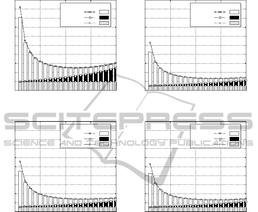
Next, as shown in Fig. 2 and Fig. 4, a cooperation
phase consists of consecutive and synchronized slots.
These slots are classified into three categories; idle
slots of duration T
slot
, slots with 1-frame transmission
of duration of T
succ
or T
fail
, and slots with frame colli-
sions of duration of T
fail
. Clearly, one slot in slots with
1-frame transmission is a successful slot of duration
of T
succ
which is the last slot in a cooperation phase.
Fig. 8 shows the average number of slots in a cooper-
ation phase, classified into the three categories. The
average number of these slots are theoretically eval-
uated as (10)–(12). Predictably, the average number
of slots with frame collision monotonously increases
in proportion to increment of the number of active re-
lay nodes. The average number of idle sots decreases
SENSORNETS2014-InternationalConferenceonSensorNetworks
162
0
2
4
6
8
10
12
14
16
18
20
0 5 10 15 20
Average Number of Slots
Number of Active Relay Nodes: N
Sim.Theory
Idle
Collision
1-Frame
(a) For L = 1 and (ε
SD
,ε
RD
) = (10
−1
,10
−2
)
0
2
4
6
8
10
12
14
16
18
20
0 5 10 15 20
Averege Number of Slots
Number of Active Relay Nodes: N
Sim.Theory
Idle
Collision
1-Frame
(b) For L = 2 and (ε
SD
,ε
RD
) = (10
−1
,10
−2
)
0
2
4
6
8
10
12
14
16
18
20
0 5 10 15 20
Averege Number of Slots
Number of Active Relay Nodes: N
Sim.Theory
Idle
Collision
1-Frame
(c) For L = 1 and (ε
SD
,ε
RD
) = (10
−2
,10
−3
)
0
2
4
6
8
10
12
14
16
18
20
0 5 10 15 20
Averege Number of Slots
Number of Active Relay Nodes: N
Sim.Theory
Idle
Collision
1-Frame
(d) For L = 2 and (ε
SD
,ε
RD
) = (10
−2
,10
−3
)
Figure 8: Slot distribution in cooperation phase.
on the contrary. The incorporation of RP-MDS suc-
cessfully facilitates the completion of a cooperation
phase. Therefore, the average number of slots with
1-frame transmission can be reduced by the use of the
proposed protocol. Particularly, the use of RP-MDS
can approximately halve the average number of slots
for (ε
SD
,ε
RD
) = (10
−1
,10
−2
), comparing Fig. 8(a) to
Fig. 8(b).
7 CONCLUSIONS
We have proposed incorporation of RP-MDS, which
has been proposed for multi-hop cooperative relay
networks (Sakakibara et al., 2011), to PRCSMA over
noisy channels. The proposed protocol elaborately
takes advantage of the powerfulerror-correctingcapa-
bility of MDS codes into cooperative communication
systems and introduces the incremental redundancy
concept to PRCSMA. A destination node can rein-
force the error-correcting capability when it receives
a new frame. Assuming symmetric relay channels,
we have analyzed the performance of the proposed
protocol in terms of the average duration of a cooper-
ation phase and the energy efficiency in a cooperation
phase. The accuracy of theoretical results has been
validated by means of computer simulation. Numer-
ical results have indicated that the proposed protocol
can improve the performance, compared to the orig-
inal PRCSMA, particularly over severe noisy chan-
nels. It is also revealed that the use of a half-rate MDS
PerformanceAnalysisofRandomRelayingofPartitionedMDSCodewordBlockAppliedtoPersistentRelayCSMAover
RandomErrorChannels
163

code suffices in the proposed protocol.
Further study includes, for example, the consider-
ation of header errors and feedback errors, and the ex-
tension to bidirectional communication systems and
to the use of network coding.
ACKNOWLEDGEMENTS
This work was partly supported by Japan Society for
the Promotion of Science under Grant-in-Aid for Sci-
entific Research (C) (KAKENHI no. 25420379).
REFERENCES
Alonso-Zarate, J., Alonso, L., and Verikoukis, C. (2009).
Performance analysis of a persistent relay carrier sens-
ing multiple access protocol. IEEE Trans. Wireless
Commun., 8(12):5827–5831.
Bhamri, A., Kaltenberger, F., Knopp, R., and Hamalainen,
R. (2011). Smart hybrid-ARQ (SHARQ) for coop-
erative communication via distributed relays in LTE-
advanced. In Proc. IEEE SPAWC 2011, pages 41–45.
San Francisco, CA.
Bianchi, G. (2000). Performance analysis of the IEEE
802.11 distribution coordination function. IEEE J. Se-
lect. Areas Commun., 18(3):535–547.
Dianati, M., Ling, X., Naik, K., and Shen, X. (2006). A
node-cooperative ARQ scheme for wireless ad hoc
networks. IEEE Trans. Veh. Tech., 55(3):1032–1044.
G´omez-Cuba, F., Asorey-Cacheda, R., and Gonz´alez-
Casta˜no, F. J. (2012). A survey on cooperative diver-
sity for wireless networks. IEEE Commun. Surveys &
Tutorials, 14(3):822–835.
IEEE Standard 802.11 (1999). Part 11: Wireless LAN
medium access control (MAC) and physical layer
(PHY) specification. Piscataway, NJ.
Loa, K., Wu, C.-C., Sheu, S.-T., Yuan, Y., Chion, M., Huo,
D., and Xu, L. (2010). IMT-advanced relay standards.
IEEE Commun. Mag, 48(8):40–48.
Morillo, J. and Garcia-Vidal, J. (2011). A cooperative-ARQ
protocol with frame combining. Wireless Networks,
17(4):937–953.
Peterson, W. W. and Weldon, Jr., E. J. (1972). Error-
Correcting Codes. MIT Press, second edition. Cam-
bridge, MA.
Predojev, T., Alonso-Zarate, J., Alonso, L., and Verikoukis,
C. (2012). Energy efficiency analysis of a coopera-
tive scheme for wireless local area networks. In Proc.
IEEE GLOBECOM 2012, pages 3183–3186. Ana-
heim, CA.
Pursley, M. B. and Sandberg, S. D. (1989). Delay and
throughput for three transmission schemes in packet
radio networks. IEEE Trans. Commun., 37(12):1264–
1274.
Sakakibara, K., Kobayashi, S., and Taketsugu, J. (2011).
Outage probability of random relying of MDS code-
word blocks in cooperative multi-hop networks. In
Proc. Intl. Congr. Ultra Modern Telecommun. Control
Sys. (ICUMT 2011). Budapest, Hungary.
Wicker, S. B. (1995). Error Control Systems for Digital
Communication and Storage. Prentice-Hall. Engle-
wood Cliffs, NJ.
SENSORNETS2014-InternationalConferenceonSensorNetworks
164
