
A Proposal for an Internet of Things-based Monitoring System
Composed by Low Capability, Open Source and Open Hardware
Devices
Jesús Rodríguez-Molina, José-Fernán Martínez, Gregorio Rubio and Vicente Hernández
CITSEM - Centro de Investigación en Tecnologías Software y Sistemas Multimedia para la Sostenibilidad
Technical University of Madrid, La Arboleda Campus Sur UPM. Ctra. Valencia, Km 7, 28031, Madrid, Spain
Keywords: Internet of Things, Monitoring, Application, Middleware, Architecture.
Abstract: The Internet of Things makes use of a huge disparity of technologies at very different levels that help one to
the other to accomplish goals that were previously regarded as unthinkable in terms of ubiquity or
scalability. If the Internet of Things is expected to interconnect every day devices or appliances and enable
communications between them, a broad range of new services, applications and products can be foreseen.
For example, monitoring is a process where sensors have widespread use for measuring environmental
parameters (temperature, light, chemical agents, etc.) but obtaining readings at the exact physical point they
want to be obtained from, or about the exact wanted parameter can be a clumsy, time-consuming task that is
not easily adaptable to new requirements. In order to tackle this challenge, a proposal on a system used to
monitor any conceivable environment, which additionally is able to monitor the status of its own
components and heal some of the most usual issues of a Wireless Sensor Network, is presented here in
detail, covering all the layers that give it shape in terms of devices, communications or services.
1 INTRODUCTION
The Internet of Things (or the IoT) offers an plethora
of possibilities unlike any other previously existing
system. The number of electronic devices that are
present in the world are but ever-increasing at a fast
pace, along with the willingness to interconnect
them, thus establishing communications where data
is shared in an efficient and seamless manner. The
number of applications or projects related with the
IoT has boomed, going from Near Field
Communications in Peer-to-Peer transactions (Urien,
2013) to applications related with cloud computing
(Pereira et al., 2013), to name but a few. A
significant amount of proposals revolve around the
concepts of either providing services for human
users or supplying a sort of machine-to-machine
communication (M2M) within a system.
Incidentally, it is only natural that the state of things
turns out like this, as Mark Weiser, the forerunner of
ubiquitous computing, claimed that machines would
end up being so integrated within an environment
that they would just recede to the background
(Weiser, 1991). Therefore, electronic appliances
must communicate one to the other requiring as little
user intervention as possible. To accomplish this
duty, many systems have been conceived and
designed that are implementing features from the
vision of the IoT (context awareness, ubiquitous
computing, always-on connectivity, environment
integration, etc.) to become an actual characteristic
of a deployment.
Among the most usual IoT-related applications,
the ones involving e-Health (Zhan et al., 2012) and
surveillance are rather common; unfortunately, they
often share several flaws: these applications are
restricted to a specific area of usability, and if
yanked out of it they do not seem to adapt with
easiness to other surroundings. What is more, even if
their natural environment remains the same, should
any other new service be included as part of a
system update, they do not offer enough flexibility
to make that service usable from the very first
moment. Finally, despite many solutions offer an
impressive performance, they tend to fare poorly
whenever there is any kind of defect in the deployed
system (faulty network nodes, damaged sensors). In
this paper, we are presenting a proposal able to
87
Rodriguez-Molina J., Martínez J., Rubio G. and Hernández V..
A Proposal for an Internet of Things-based Monitoring System Composed by Low Capability, Open Source and Open Hardware Devices.
DOI: 10.5220/0004697900870094
In Proceedings of the 3rd International Conference on Sensor Networks (SENSORNETS-2014), pages 87-94
ISBN: 978-989-758-001-7
Copyright
c
2014 SCITEPRESS (Science and Technology Publications, Lda.)
diagnose and self-heal most common issues that
spring up in domains typical of an IoT system –as
Wireless Sensor Networks, distributed middleware
or embedded systems-. Plus, not only is our proposal
able to provide services to human users, but also
provides information of the most prominent
characteristics to be taken into account from the
system elements (battery level, transmission power,
etc.). Additionally, rather than having a system
tailored to work in only a specific area, one able to
be adapted for different purposes has been designed,
with very little effort required to do any adaptation
to new circumstances.
2 AN OVERVIEW OF THE
DESIGNED SYSTEM
The major components that are present and their
tasks are as follows:
Device layer. This layer is comprising all the
hardware and all the appliances required. It will be
responsible for gathering all the required context
data whenever a request is taking place. In our
suggested proposal, the system will be using Sun
SPOT motes (Oracle, 2010), MEMSIC Iris motes
(MEMSIC, 2013) and Arduino Uno boards
(Arduino, 2013) conveniently equipped with extra
sensors, which may be equipped by the motes as
well.
Communications layer. This layer is in charge of
the communications that may take place. There are
two domains where communication operations
happen; initially, there is a regular domain, with
connections based on Internet Protocol at the
network layer and Transmission Control Protocol or
User Datagram Protocol at a higher level. On the
other hand, there will be another domain where
802.15.4, an IEEE standard designed for low
capability devices, will be used as the wireless
protocol of choice. IEEE 802.15.4 is considered here
to be used for the monitoring system domain, as well
as for internode communications, while the usual
network architecture works on the application layer.
Middleware layer. Up until this point the
presented layered model is a unity, despite having
different objectives. However, since the applications
that are going to be run are implying different areas
of usefulness, it is advisory to split the higher levels
of the architecture in order to better deal with
challenges related with lower level communications.
While information transfer will be made in usual
terms, management will take a very different
approach. In the latter environment, requests and
responses are done with a middleware layer that has
been named Request and Response Adapter Protocol
(RRAP). This middleware level will establish a
protocol –effectively standardizing communications
under the scope of the management part of the
system- used for data traffic aimed to get
information related with the status of the system.
Plus, messages will be sent to the upper layer if any
important event comes up, so that the human user
will be aware of relevant changes in the system.
Application layer. This level is split in two parts
of equal level but fulfilling different functionalities:
a web browser that, regardless of the different ones
available (Mozilla, Chrome, Opera, IE, Safari, etc.),
will process the requests done, and a Graphical User
Interface especially made for the management part
of the system. This GUI will come in handy both for
status requests and notifications.
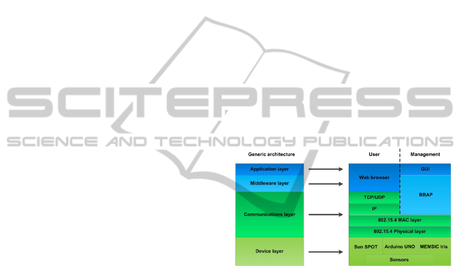
The system has been portrayed as a layered
architecture in Figure 1. User part is made for user
requests and responses, while management part is
bent on monitoring the system itself.
Figure 1: A holistic view of the whole architecture.
After introducing the most important features of
the proposal, each of the designed layers will be
described in detail in the following sections.
2.1 Device Layer
Whenever a data request has to be fulfilled, device
layer is the one with the suitable components to
obtain the requested information. Being at the
bottommost part of our proposal, this layer will deal
with hardware, sensors and actuators more profusely
than any other. There are three kinds of devices that
are regarded as best-fitting for our proposal: two of
them are motes –which are low capability devices
frequently used as nodes in Wireless Sensor
Networks - of different vendors –Oracle Sun SPOT
and MEMSIC Iris- and the third one is the Arduino
Uno board, a device for open hardware and software
SENSORNETS2014-InternationalConferenceonSensorNetworks
88

developments. The main features of these devices
are displayed in Chart 1.
Device
Clock
speed
RAM-Flash Features
Oracle
Sun SPOT
400
MHz
1Mbytes-
8Mbytes
Capable of
running
HTTP
MEMS
IC Iris
8
MHz
8Kbytes-
128Kbytes
Java or
nesC
lan
g
ua
g
es
Arduin
o Uno
16
MHz
2Kbytes-
32Kb
y
tes
Sensor
flexibilit
y
Chart 1: Device layer components relevant data.
The device layer is conceived as a Wireless
Sensor Network with the following components:
a) Base station/Sink, which is directly connected
to the device that has the web browser and the GUI
installed and running. Base station/Sink must be
capable of managing information at the application
layer, as HTTP requests will have to be attended by
it and sent to the devices that cannot handle
information at layers as high as this. Since this node
will behave as a bridge between the HTTP and the
IEEE 802.15.4 domain, most of the petitions can
involve obtaining data of different nature. Among
the already mentioned devices, Sun SPOT Base
station/Sink usage is mandatory here, for it is the
only device present in our proposal with a HTTP
client. Besides, as it must be always attached to a
computer to be powered, it remains unaffected by
energy issues typical of Wireless Sensor Networks.
b) Slave nodes, which are connected to the Base
station/Sink wirelessly by using standard IEEE
802.15.4. These nodes receive the requests that are
meant to be answered by them; the requests will be
sent by the Base station/Sink as soon as there is a
petition at the web browser-enabled device. One
very important feature of Slave nodes is that they
can notify several issues that they may be suffering
from; RRAP has a specific PDU that will be sent
from a Slave mote to the most powerful-emitting
node if it detects any performance strangling issue
(for example, the battery is almost completely
depleted). It must be noted that although nodes are
physical devices, roles are purely made up by
software, and their functionalities can be transferred
from one node to another. According to the
capabilities of the used devices, roles can be either
activated if they are dormant (a more efficient option
if energy consumption is taken into account) or
being programmed Over-The-Air (OTA
programming). In this case, either Sun SPOT motes
or MEMSIC Iris ones can be used, as application
layer features are not required at this part of the
topology. Having equipment from different vendors
communicating to each other at the same level can
be a feature especially prone to interoperability
issues: as it is known (Akribopoulos et al., 2011)
there may be incompatibilities due to payload sizes
or addresses lengths, regardless of claiming that they
are all using the same standard, as IEEE 802.15.4.
Fortunately, any trouble that may be encountered
should have been solved before by the RRAP
implementation, and the work done at that point will
be interesting to be considered for future
interoperability challenges.
c) Auxiliary sensing devices. Nodes are made by
actual devices that have several built-in sensors and
actuators used for information provisioning;
nevertheless, if they can be expanded so as to supply
some information of different nature, then the end
users will have more information at their disposal.
The system capacities can be improved by using
electronic devices with low capabilities, as the only
requirement for them will be measuring data and
delivering it to its requester, without any other need
of routing it anywhere. Consequently, available
interfaces of the nodes can behave as ports for
external data coming from other sensors and/or
actuators alien to the node. More specifically,
Arduino Uno boards are a very suitable option for
this challenge; their capabilities are low enough to
guarantee that they will not require a huge amount of
power but, at the same time, will be able to store any
small program –or sketch, as they are referred to-
able to retrieve data. Provided that the needed
elements –photoresistors, thermoresistors, etc- are
available, obtaining readings from them can be done
by plugging any element to a breadboard, mapping
power references (power supply and ground) to the
breadboard and getting the element reading as an
analog or digital input for the Arduino Uno,
provided that the pin mapping has been previously
programmed. As displayed in Figure 2, an Arduino
board can be turned into a sensing/actuating device;
in the shown case, a switch is used to change from
one sensor to another and to the actuator, thus
having a LED, a photoresistor and a thermistor
taking turns to execute their actions whenever the
switch is pressed. In the proposed system, either
cabling to a port available at a node or, as shown in
Figure 2, adding a 802.15.4 XBee communication
module can be used if a mote is wanted to be
augmented with an Arduino board -as it may come
in handy to test a service of similar nature in devices
placed differently, and soldering may not be
AProposalforanInternetofThings-basedMonitoringSystemComposedbyLowCapability,OpenSourceandOpen
HardwareDevices
89
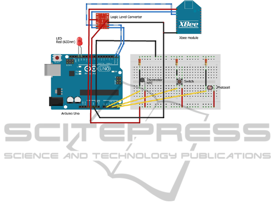
Figure 2: An Arduino-built, 802.15.4-enabled sensing/actuating.
required- or the Arduino-built sensing/actuating
device is preferred to run separately, as it will
effectively turn into a low-cost mote.
2.2 Communications Layer
In contrast with the particularity of the physical one,
communications layer uses several standard
technologies. As far as networking is concerned,
there are two kinds of domains in the proposal to be
taken care of: internode communications and web
communications. As already mentioned, the first
domain is interconnected by using IEEE 802.15.4
standard, for it consumes a low amount of energy
and the available bandwidth, although scarce (only
up to 250 KBps), is more than enough for what is
expected to be done by nodes in Wireless Sensor
Networks. Plus, many of these devices are already
equipped with antennas enabled with the standard,
and almost any Arduino board can be equipped with
a shield using a XBee module. IEEE 802.15.4
standard is divided in two different layers: a physical
one and a Medium Access Control (MAC) one. The
former deals mostly with the channels available for
transmission (usually, there are sixteen channels
available in the 2450 MHz band, ten at the 915 MHz
and one at the 868 MHz band) and their frequencies,
while the latter is involved in tasks typical of a MAC
layer, as implementing a mechanism based on ARQ
(Automatic Repeat Request) so as to guarantee error
correction (Singh and Pesch, 2011). It must be
mentioned at this point that ZigBee is not IEEE
802.15.4; rather than that, ZigBee is a consortium
devoted to the application layer services that may be
able to be built upon the physical and MAC layers of
IEEE 802.15.4.
The second domain that is present in our
proposed system is a regular TCP/IP architecture.
This domain has been placed higher in the layered
architectural model as communications from the
application layer will be transferred through an
implementation supported on TCP/IP, while IEEE
802.15.4 communications are not expected to be
routed as the TCP/IP-based ones are. Data transfer is
done as usual: information regarding requests and
responses is routed through a packet switched
network and, depending on whether TCP or UDP
has been chosen as the transport layer protocol, data
transport will be done either at a slightly slower but
more reliable way, enabling error correction and
data retransmission (TCP) or at a more real time-like
pace, risking the loss of information in the process
(UDP). Judging from the data requirements of our
system, it is considered that UDP is good enough, as
it is important to get information quickly and
chances of having data segments dropped should be
fairly low. Considering how communications will be
tackled, as well as which areas are using one
architecture or another, network topology can be
separated now in different areas involving different
communication domains, as it has been portrayed in
Figure 3.
2.3 Middleware Layer
Middleware is envisioned as fulfilling an extremely
important task as far as the IoT or Wireless Sensor
Networks are concerned, for it will adapt all the
SENSORNETS2014-InternationalConferenceonSensorNetworks
90
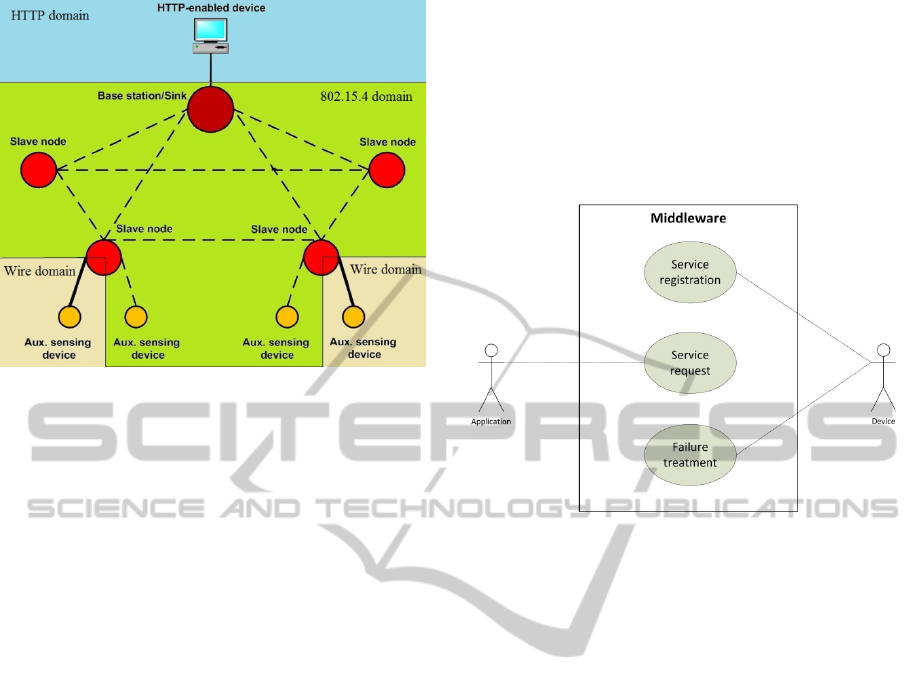
Figure 3: Network topology separated by communication
domains.
heterogeneity of the device layer components, and
all the hardware disparity, into a homogeneous-
looking collection of operations and interfaces.
Noha Ibrahim, which provides a taxonomy on
middleware architectures, claims that “They have
evolved from simple beginnings - hiding network
details from applications – into sophisticated
systems that handle many important functionalities
for distributed applications - providing support for
distribution, heterogeneity and mobility” (Ibrahim,
2009). In this case, middleware will provide the GUI
at the application layer with several operations in
terms of management and status report. The
middleware layer has been deliberately left outside
the user architecture part because the services and
functionalities present at this side of the architecture
stack are considered to be tackled by regular layered
components, and it is in our interest designing a
model where Web Services and Wireless Sensor
Network-oriented ones can coexist under the same
system. Nevertheless, since the management part is
accessing to the Wireless Sensor Network nodes, it
would be possible to obtain data from the network
regarding sensor readings.
The middleware layer that has been designed is
named Request Response Adapter Protocol (RRAP).
It is an accurate name because it is going to adapt all
the requests that are made from the GUI to a specific
Processing Data Unit (hereinafter, PDU) format
flowing through the Wireless Sensor Network, and
responses will be treated the same way, albeit on the
opposite direction (from the Wireless Sensor
Network to the GUI). While there are several
different types of PDUs, they are managed in a way
that human operators do not perceive the disparities;
their variety is due to the fact that the top design
criterion was using as few data in radio transmission
as possible for service provisioning, as radio
messages are the most energy-demanding operation
in a Wireless Sensor Network (Bachir et al., 2010).
RRAP is responsible for tackling several actions that
must be performed; they have been depicted in the
use case diagram presented in Figure 4.
Figure 4: Use case diagram for the proposal.
Service registration. In order to have retrievable
services, the Base station/Sink must be aware of
them, so whenever a node is turned on, it will
broadcast a PDU with all the available services that
can be obtained either by its built-in sensors or from
any Arduino Uno board. This is the only PDU that
must be transmitted in broadcast mode rather than
unicast, as the node is unaware of where the Base
station/Sink is. Its fields will consist of a node
identifier (that may be varying from one tailored for
the system to a MAC address, as available in Sun
SPOT motes) and service identifiers for the services
available at a node, along with their parameters. The
different components of this packet have been
presented in Figure 5.
Service requests. Whenever there is a query
involving management services, it will be
transmitted towards the Wireless Sensor Network
from the Base Station/Sink in the simplest possible
manner. Therefore, unambiguous identifiers will be
used to do the request. To begin with, a request on
the available services from the system can be done.
As it will be the most generic and information
abundant query, there is very little need to have
many particularizing fields in the PDU that is
transmitted towards the Wireless Sensor Network. In
fact, if service registration has been done without
anomalies, this request could not be mandatory, as
data involving registered services can be stored at
AProposalforanInternetofThings-basedMonitoringSystemComposedbyLowCapability,OpenSourceandOpen
HardwareDevices
91
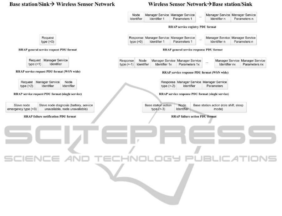
Figure 5: RRAP PDU formats.
the host application running at the Base station/Sink.
As it is displayed in Figure 5, this request PDU
(labelled as type 0) will consist of just a field
characterizing the petition, while the PDU
containing the response results will be larger, as it
must include service identifiers and parameters that
are retrieved.
As the Base Station/Sink receives the available
services that were offered by specific Wireless
Sensor Network nodes, the service request message
does not require a node identifier, although the
response may vary depending on whether a reading
from a single node was requested or an overall value
that can be obtained from the whole Wireless Sensor
Network. This has been designed this way because
having a flexible way to request different
information is a desirable feature of the system.
For example, if power transmission is requested
from all the existing nodes, a PDU where the only
feature that is necessary for the request to be made is
the manager service identifier (e.g., in case a query
made to learn the available services is executed) is
sent. When the response is obtained, it will be done
by providing the manager services and their
parameters from each of the nodes. This interchange
has been depicted in Figure 5 with a 1X-nX
identifier, where 1-n acts as the node identifier and x
as the service one, as it is likely that there are several
different services running, along with their
corresponding parameters.
On the contrary, if a management reading from a
single service from a specific of the Wireless Sensor
Network is requested, then the PDU will look as
presented in Figure 5: a node identifier and a single
manager service identifier are used to address the
node. As the services and the entities providing them
were registered before, the Base station/Sink is
aware of where to find the node that will satisfy the
request. Afterwards, when an answer is retrieved,
only the service and the parameters the Base
station/Sink is expected to fulfil from the single
node are retrieved.
The entities that are involved in the described
information exchanges, along with the particular
exchanges, have been depicted in Figure 6.
Failure treatment. The system is also taking into
account whenever there is a failure in the Wireless
Sensor Network. Without any unforeseen event,
slave nodes may be faulty due to three different
kinds of reasons: either their battery is about to run
out of power, a service has become unavailable (for
example, a sensor has been damaged or an Arduino
board connection to a slave node has failed) or the
node has become unavailable (it is no longer able to
transmit/receive data). When one of these issues is
taking place, the slave node sends a PDU as depicted
in Figure 5 to the Base station/Sink announcing the
problem. The next step will be taken by the Base
station/Sink itself: either it will put the node in a
sleep mode in order to reduce energy consumption,
or the role it is performing –that is to say, the
parameters that are being collected- will be moved
to another node. As it was done before, the entities
involved in this use case are depicted in Figure 6.
2.4 Application Layer
The application layer is made by two different
entities: a web browser and a Graphical User
Interface. The web browser is expected to be used
SENSORNETS2014-InternationalConferenceonSensorNetworks
92
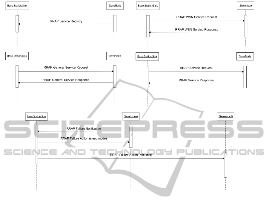
Figure 6: Entities involved in data transfers and failure treatment.
from any device capable of having a Sun SPOT base
station plugged to a USB port. It is mandatory that
the appliance the base station is plugged to is at the
same time connected to the Internet, as the appliance
will be in charge of providing a reliable IP address
to the Base station/Sink from where services can be
requested; otherwise neither the Base station/Sink
nor the services from the Wireless Sensor Network
can be retrieved. Sun SPOT motes will have an
HTTP server installed that will be listening to any
request done from the web, and whenever there is an
invocation it will be sent to the suitable node. For
example, if luminosity from a node placed in a room
numbered as 45 at the second floor in an industrial
facility, then the service could be requested as:
http://192.168.10.25:1267/spot-
79E3/luminosity/industrial/2nd/45
In this example, the fields present at the Uniform
Resource Identifier (URI) are:
192.168.10.25 as
the IP address of the device the Sun SPOT base
station is connected to (which in fact behaves as a
gateway from/to the Wireless Sensor Network),
1267 as the port used for the communications,
spot-79E3 representing the name of the devices
manufactured by the vendor, while
79E3 are the last
four digits of the mote MAC address.
Luminosity
is the name of the requested service. Finally,
industrial/2nd/45 is the path that has been
established to reach the specific device, which will
be defined at the implementation stage. Responses
can be watched at the device the Base station/Sink is
plugged to in a variety of formats. If data is to be
given any sort of hierarchy, XML or JSON formats
suit fine for this purpose. Iris motes not executing
HTTP petitions will be communicating to Sun
SPOTs via 802.15.4 data interchange whenever a
service only the former are able to provide is
queried. At the same time, a Graphical User
Interface must be enabled for the monitoring of the
current capabilities of the Wireless Sensor Network.
Using a Java-based Base station/Sink that is able to
run Java applications as if it was a communications
host, a GUI can be developed.
AProposalforanInternetofThings-basedMonitoringSystemComposedbyLowCapability,OpenSourceandOpen
HardwareDevices
93

3 USE CASE SCENARIOS
There are many environments where this monitoring
system can be used.
Agricultural facilities. In this field, several
parameters that can be easily measured by the
proposed system (Sun luminosity, environmental
temperature, humidity) are of critical importance for
crops development or cattle care.
Infrastructure monitoring. Material stress or
infrastructural wobbling can be surveyed by this
proposal as well by making use of either built-in
mote sensors or any other that may have to be added
to the Arduino Uno boards.
Tertiary and domestic environments. Our
proposal can be used to improve control on how
energy is spent for more efficient heating or lighting.
Storage that has to be done under special
temperature conditions may benefit from the usage
of the proposed system as well.
Mineral exploitations. Gas sensors are at its
finest here; firedamp deposits are a major concern in
places where mineral extraction is prominently made
by human miners instead of mining machines, and
tunnel tilts can be measured as well for collapse
prevention (for example, by using sunSPOT motes
accelerometer).
4 CONCLUSIONS
A proposal for a holistic architecture, which has as
objectives providing measurement readings from a
Wireless Sensor Network, and is able to self-monitor
and self-heal itself from critical conditions that make
a node unavailable has been displayed. Unlike other
proposals, this one stresses the usage of open
devices that can not only be programmed to deploy
any piece of software (as SunSPOT or MEMSIC
motes) but also can be designed from the very
foundations of what is wanted to be measured, by
adding wanted sensors to an Arduino Uno board.
Besides, the proposal is not constrained to a specific
domain, as the data can be retrieved regardless of the
place where the system is deployed.
ACKNOWLEDGMENTS
The work presented in this article has been partially
funded by the Spanish Ministry of Economy and
Competitiveness in the framework of Research
Project AWARE- Accessible Wearable Device
Platform for Smart Environments (Ref. TEC2011-
28397). The work shown in this proposal has been
made by staff belonging to the GRyS (Next
Generation Networks and Services Group, Grupo de
Redes y Servicios de Próxima Generación) which is
part of the CITSEM (Research Center on Software
Technologies and Multimedia Systems for
Sustainability).
REFERENCES
Urien, P. LLCPS: A new security framework based on TLS
for NFC P2P applications in the Internet of Things.
Consumer Communications and Networking
Conference (CCNC), 2013 IEEE.
Pereira, P. P., et al. Enabling Cloud Connectivity for
Mobile Internet of Things Applications. IEEE 7th
International Symposium on Service Oriented System
Engineering (SOSE), 2013.
Weiser, M., The computer for the 21st century. Scientific
American, 1991. 265(3): p. 94-104.
Andong Zhan, Marcus Chang, Yin Chen, and Andreas
Terzis. 2012. Accurate caloric expenditure of
bicyclists using cellphones. Proceedings of the 10th
ACM Conference on Embedded Network Sensor
Systems. 2012.
Oracle/Sun, Sun™ SPOT Main Board Technical
Datasheet, Oracle. October 2010.
MEMSIC Iris datasheet, http://www.memsic.com/userfiles/
files/Datasheets/WSN/IRIS_Datasheet.pdf, M. Inc.
2013.
Arduino. Arduino Uno web site. 2013; from: http://
arduino.cc/en/Main/arduinoBoardUno.
Akribopoulos, O., et al. Building a Platform-Agnostic
Wireless Network of Interconnected Smart Objects.
Panhellenic Conference on Informatics (PCI). 2011.
Singh, J. and D. Pesch. Enhancement of IEEE 802.15.4
MAC layer to combat correlated channel errors. IEEE
International Symposium on a World of Wireless,
Mobile and Multimedia Networks (WoWMoM). 2011.
Ibrahim, N. Orthogonal Classification of Middleware
Technologies. Third International Conference on
Mobile Ubiquitous Computing, Systems, Services and
Technologies UBICOMM '09. 2009.
Bachir, A., et al., MAC Essentials for Wireless Sensor
Networks. Communications Surveys & Tutorials,
IEEE, 2010. 12(2): p. 222-248.
SENSORNETS2014-InternationalConferenceonSensorNetworks
94
