
Pose Recognition in Indoor Environments using a Fisheye Camera
and a Parametric Human Model
K. K. Delibasis
1
, V. P. Plagianakos
1
and I. Maglogiannis
2
1
University of Central Greece, Department of Computer Science and Biomedical Informatics, Lamia, Greece
2
University of Piraeus, Dept. of Digital Systems, Piraeus, Greece
Keywords: Human Activity Detection, Computer Vision, Fisheye Camera Modeling, 3D Human Modeling, Posture
Recognition.
Abstract: In this paper we present a system that uses computer vision techniques and a deformable 3D human model,
in order to recognize the posture of a monitored person, given the segmented human silhouette from the
background. The video data are acquired indoors from a fixed fish-eye camera placed in the living
environment. The implemented 3D human model collaborates with a fish-eye camera model, allowing the
calculation of the real human position in the 3D-space and consequently recognizing the posture of the
monitored person. The paper discusses the details of the human model and fish-eye camera model, as well
as the posture recognition methodology. Initial results are also presented for a small number of video
sequences, of walking or standing humans.
1 INTRODUCTION AND
RELATED WORK
The field of automated human activity recognition
utilizing fixed cameras in indoor environments has
gained significant interest during the last years. It
finds a wide variety of applications in diverse areas,
such as assistive environments, supporting the
elderly or the chronic ill, surveillance and security,
traffic control, industrial processes etc. This work
focuses in pose estimation of walking or standing
human from fisheye video: therefore human
silhouette segmentation of the video sequence is a
prerequisite. The proposed algorithm is based on a
parametric three-dimensional (3D) human model
that can move its legs and arms, as well as on a
model of the fisheye camera that allows the
rendering of the parametric model. An evolutionary
optimization algorithm is used to recover the
parameters of the 3D human model.
The first step in applications dealing with human
activity recognition from video is foreground
segmentation. Most of the video segmentation
algorithms are based on background subtraction. The
background has to be modelled, since it may change
due to a number of reasons, including: motion of
background objects, differences in light conditions,
or video compression artefacts. Therefore, a number
of techniques have been proposed for constructing a
model of the background that is being gradually
updated using the values of the current video frame.
In (Willems 2009) the background model is defined
as the previous frame. Background can be modelled
by median filtering (Cucchiara 2003) of a predefined
number of last frames that are hold in a buffer. The
background value of each pixel in the model is
independently computed as the temporal median of
the pixel values along the buffer. This approach
however may become slow for large frame sizes.
Other approaches (eg. McFarlane and Schofield
1995, or the running average Willems 2009) use an
incremental update of the background, without the
need of a buffer to store previous frames. An
extension of the aforementioned methods is the
running Gaussian average which was proposed in
(Wren 1997). A more complex but popular
segmentation algorithm is the Mixture of Gaussians
(MoG), initially described for video sequences by
Stauffer and Grimson (1999).
In this work we have performed video
segmentation using the illumination sensitive
method (Cheng 2011), as implemented in
(Christodoulidis 2012). This technique is based on
the entropy calculation of each frame and it solves
the problem of sudden illumination changes, which
470
Delibasis K., Plagianakos V. and Maglogiannis I..
Pose Recognition in Indoor Environments using a Fisheye Camera and a Parametric Human Model.
DOI: 10.5220/0004693704700477
In Proceedings of the 9th International Conference on Computer Vision Theory and Applications (VISAPP-2014), pages 470-477
ISBN: 978-989-758-004-8
Copyright
c
2014 SCITEPRESS (Science and Technology Publications, Lda.)

affect significantly the background modelling.
Therefore it is considered appropriate for the
proposed system.
Regarding the human silhouette modelling,
articulated stick human models are quite popular for
pose estimation. Volumetric human models use
geometric primitives such as are spheres, cylinders
or tapered super-quadrics (Delamarre 2001), (Kehl
2006). Surface-based models of the human body
typically consist of a mesh of polygons that may be
deformed (Barron 2001).
Pose estimation is achieved by recovering the
values of the human model parameters. A number of
reported works use the “top-down estimation”, by
comparing the rendered 3D human model with the
actual frame, using local search methods (Bregler
2004).
A small number of approaches use information
about the camera model and setting, to assist pose
recovery. In (Taylor 2000) the perspective
information of a mono-occular camera is used. In
(Liebowitz 2003) reconstruction of 3D poses from
2D point correspondences is reported, using multiple
views and known body segment lengths. Detailed
description of these approaches can be found in the
survey of (Poppe 2007).
In the proposed system video is captured using
360 degrees field of view (FoV) hemispheric
cameras, also known as fisheye cameras. The
utilization of fisheye cameras is increasing both in
robotic applications and in video surveillance
(Kemmotsu 2006), (Zhou 2008). In (Saito 2010) a
probabilistic model of pedestrians imaged by a
fisheye camera is utilized. As fisheye cameras with
megapixel sensors are now available, research in
calibration of such cameras becomes increasingly
useful. Thus, the topic of fish-eye camera calibration
has attracted significant attention, on its own. In (Li
2006) and (Basu 1993) the calibration of fisheye
camera is reported using high degree polynomials to
emulate the strong deformation effects introduced by
the fisheye lens. In (Shah 1996) a detailed model is
presented for fisheye camera calibration, which
estimates the radial and tangential deformation,
using a polynomial mapping between the radial
distance from the optical axis of a real world point
and its imaged point on the image plane. In this
work, we employ the forward and inverse camera
model that was proposed in (Delibasis 2013).
Regarding human modeling we employ a simple
triangulated 3D parametric model with a number of
degrees of freedom and follow a “top-down”
approach by matching the model rendered through
the calibrated fisheye camera, with the segmented
frame of the video. Evolutionary optimization is
used to recover the model parameters and determine
human motion and pose. The range of the
parameters of the model is narrowed, using the
segmentation refinement algorithm that we proposed
in (Delibasis 2013). The rest of the paper is
structured as follows: Section 2 discuss the technical
details of the proposed algorithms and techniques,
Section 3 presents some initial results and finally
Section 4 concludes the paper.
2 MATERIALS AND METHODS
2.1 Overall Architecture
The overall architecture of the proposed system is
illustrated in Fig. 1. It comprises of a) a model of the
fisheye camera that enables the extraction of the
direction of view of each pixel of the video frame
(originally proposed in Delibasis 2013), b) a 3D
parametric model of a human and c) an evolutionary
algorithm that recovers the parameters of the 3D
human model, based on an objective function that
compares the rendering of the 3D model through the
camera model to the segmented human.
Figure 1: The overall system architecture.
2.2 Fisheye Camera Model
The main characteristic of the fisheye camera is that
it can cover a field of view of 180 degrees. We use a
model to simulate the image formation using the
fisheye camera, so that given the real-world position
of an object (x,y,z), we may calculate the image
coordinates (j,i) of its pixels. The action of the
fisheye model M can be written in the general form
,,,ji M x yz
(1)
Calibration of
Fisheye model
Background
segmen tation
Human posture
recognition
Parametric model
of 3D Human
Fisheye
simulation
Video
input
Video Single
frame, User
measurements
Evolutionary
optimization
Performed once
Iteratedpart
Reject binary
objects
Merge binary
objects
Refinement of segmentation
of Human
PoseRecognitioninIndoorEnvironmentsusingaFisheyeCameraandaParametricHumanModel
471

We adopted a model for the fisheye camera that is
based on the physics of image formation, as
described in (Max 1983), (Greene 1986) and
demonstrated in (http://paulbourke.net/ dome/
fisheye/) and (Delibasis 2013). We consider a
spherical element of arbitrary radius R
0
with its
center at K(0,0,z
sph
) (as it will become clear soon, the
radius R
0
is not a parameter of the model). For any
point P with real world coordinates (x,y,z), we
determine the intersection Q of the line KP with the
spherical optical element of the fisheye lens. The
point P is imaged at the central projection
,
im im
x
y
of Q on the image plane with equation z=z
plane
, using
the O(0,0,0) as center of projection, assuming that
the installation of the camera is such that the
imaging plane (i.e. the image sensor) is horizontal
and the axis of the spherical lens is not misaligned.
Thus, it becomes obvious that all real world points
that lie on the KP line are imaged at the same point
,
im im
x
y of the image plane. The KP line is
uniquely defined by its azimuth and elevation
angles, θ, φ respectively. The concept of the fisheye
geometric model is shown in Fig. 2.
The fisheye camera has no moving parts.
Therefore, the ratio
s
ph plane
pz z is the primary
parameter of the fisheye model.
z
plane
is set to an
arbitrary value less than
R
0
, thus
s
ph plane
zpz . It is
possible that small internal lens misalignments may
introduce unanticipated imaging deformations (Shah
1996). Thus, we introduce two extra model
parameters, the
X and Y position of the center of
spherical lens
,
s
ph sph
x
y with respect to the optical
axis of the camera. Now the center of the spherical
element becomes K(x
sph
, y
sph
, z
sph
). Fig. 2 shows the
case for
0, 0
sph sph
xy
for simplicity. The
position of any point of the line segment KP, thus Q
as well, is given by
,, , ,
x
y z sph sph sph
QQQ x x y y z z
(2)
where λ is a parameter in range [0,1].
If we insert this into the equation of the spherical
optical element, we derive an equation whose
solution defines λ and the position of Q:
22
2
2
0
0
sph sph sph sph
sph sph
xx x yy y
zz z R
(3)
Figure 2: The geometry of the fisheye model.
The final step is the calculation of the central
projection
,
im im
x
y
of Q on the image plane:
,,
plane
im im x y
sph
z
x
yQQ
z
(4)
For any point P with real world coordinate
z>z
sph
, its projection onto the image plane
,
im im
x
y
is bounded by the radius of the virtual spherical
optical element R
0
:
00im sph
Rx x R
. When
x
then
0im sph
x
xR . The same holds for
the y coordinate. The image pixel (i,j) that
corresponds to
,
im im
x
y is calculated by a simple
linear transform:
0
,, ,
FoV
im im x y
R
j
ixy CoDCoD
R
(5)
where (CoD
x
, CoD
y
) is the center of distortion pixel
that corresponds to elevation φ=π/2 and R
FoV
is the
radius of the circular field of view (FoV). For the
fish-eye camera, (Micusik 2006) suggests that the
CoD is located as the center of the circular field-of-
view (see Fig. 3 for a typical video frame). We
therefore apply the canny edge detector, using a
standard deviation equal to 2 in order to detect the
stronger edges in the image, which are the edges of
the circular field of view. Then, we employ a simple
least squares optimization to obtain the CoD and the
radius of the FoV. This is done only once, during the
calibration of the camera model.
The calibration process of the camera model
recovers the values of the unknown , ,
s
ph sph
px y
P(x,y,z)
O(0,0,0)
(x
im
,y
im
)
K(0,0,z
sph
)
Imageplane
z=z
plane
Z
θ
φ
Q(Q
x
,Q
y
,Q
z
)
X
Y
VISAPP2014-InternationalConferenceonComputerVisionTheoryandApplications
472
parameters. The user provided the position of N
p
=18
landmark points
, , 1, 2,...,
ii
im im p
XY i N on one
video frame. The real world coordinates of these
landmark points
,,
iii
real real real
xyz were also
measured. The expected position of the landmark
points on the video frame, according to the model
parameters are (superscripts are not powers):
,,,;,,
ii i i i
im im real real real sph sph
xy Mx y z px y
(6)
The values of the model parameters are obtained by
minimizing the error between the expected and the
observed frame coordinates of the landmark points:
22
1
,,
,,
arg min
p
sph sph
N
ii ii
sph sph im im im im
i
px y
px y X x Y y
(7)
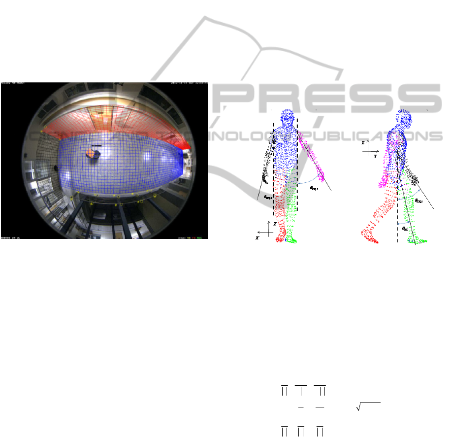
Figure 3: Visualization of the resulting fisheye model
calibration.
This minimization is performed by exhaustive
search in just few minutes using the Matlab
programming environment in an average personal
computer. Since the fisheye camera was
permanently installed on the roof of the university
laboratory, the calibration of the model is performed
only once. The resulting calibration of the fisheye
model is shown in Fig. 4, where a virtual grid, laid
on the floor and on the two walls of the imaged
room, is rendered on the captured frame, using the
fisheye model. The user-defined landmark points
are shown as ‘o’, whereas their projected location on
the video frame, using the calibrated model are
shown as ‘*’.
2.3 Human Model
In this work, we utilized a free triangulated model of
a standing human, of 27.000 vertices
(http://www.3dmodelfree.com/models/20966-
0.htm), approximately. Since we are interested in
simulating the rendering of the human model
through the fisheye camera in real time, we discard
the triangle information of the model and we treat it
as a cloud of points. We also applied a vertex
decimation process to reduce the number of vertices
by a factor of 8.
The vertices of the model were labelled using
logical spatial relations, into 5 classes: right and left
arm, right and left leg and the rest of the body (torso
and head). The pose of the human is modified by
changing the position of the hands and legs
independently, using the following controlling
parameters. Legs are allowed to rotate round the Y
axis with respect to the hips (thus they remain on the
sagital - YZ plane). Arms are allowed to rotate round
the shoulders. Fig. 4 shows an example of the
parametric human model along the coronal and the
sagital plane.
(a) (b)
Figure 4: The model of the human (anterior view and right
view), with labels as color. The axis of the limbs and their
angles with the vertical human axis, that define the
parameters of the 3D human model, are also shown.
The rotation of the hands involves all three Euler
angles. In order to avoid dependence on the order of
rotation and possible gimbal lock, we utilized the
following matrix, that transforms, a unit vector
v=(a,b,c) on the Z axis.
22
0
00
,
0
00 01
ab ac
vvv
b
bc
cc
ab c
vv v
A
(8)
Assuming that
v coincides with the axis of the
hand, matrix
A is applied to the vertices of the two
hands separately, using homogeneous coordinates.
PoseRecognitioninIndoorEnvironmentsusingaFisheyeCameraandaParametricHumanModel
473
In addition to the 6 parameters that control the arms
and legs of the model, global parameters are also
introduced that control: the model’s location (x and y
translation), size (x, y and z scaling) and global
rotation round the Z axis. In order to narrow the
range of these global parameters, we utilized the
geometric reasoning-based segmentation refinement
that we reported in (Delibasis 2013, section 2.4).
More specifically we utilize the calibrated fisheye
camera model to obtain an estimation of the real
(x
real
, y
real
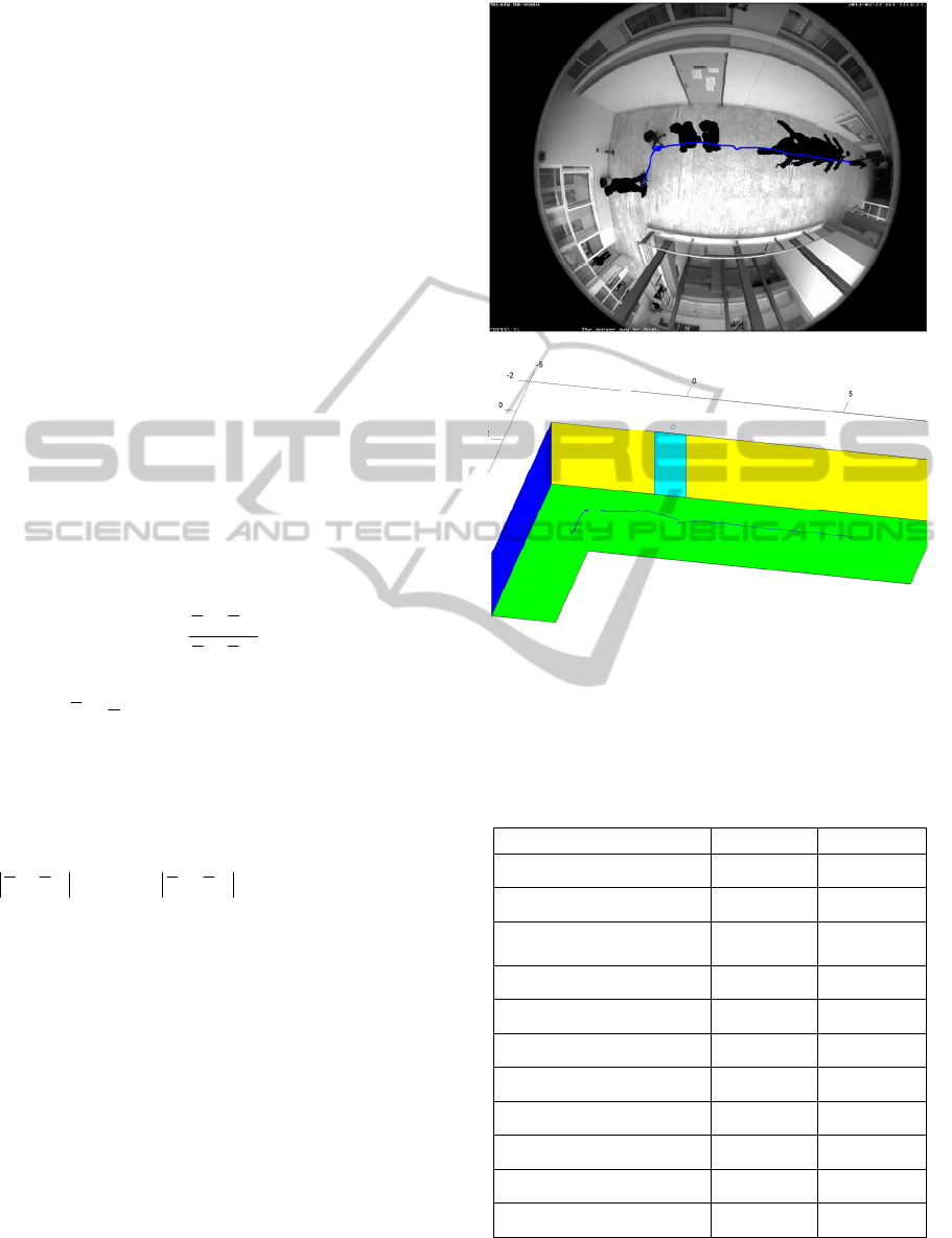
) positions of the segmented human. Some
instances of the segmented human from a typical
video are shown in Fig. 5(a), whereas the path of the
walking human in the real world frame of reference
is plotted in Fig. 5(b), as estimated using the
segmentation refinement (Delibasis 2013, section
2.4). The path is overlaid back on the composite
video frame (Fig. 5a) using the forward fisheye
model (Delibasis 2013, section 2.2).
The estimated (x
real
, y
real
) coordinates are used to
initialize the model’s location (x and y translation).
The global rotation round the Z axis, is calculated
using the direction θ
z
of the velocity vector
(assuming that the human is facing towards the
direction that he/she is walking), as following:
1
1
1
tan
tt
z
tt
yy
xx
(9)
where
12
1
3
ttt
t real real real
x xxx
is the running
average of the last estimated real world coordinates
(same hold for y
real
coordinate), which prevents
amplification of the noise, induced by errors in
position estimation.
If the human is stationary (
10 10tt t t
x
xdANDyyd
, d
0
=0.1) then the
angle θ
z
is not utilized for narrowing the range of z-
rotation angle, which is then set to [0,2π]. The range
of the model parameters are shown in Table 1.
The human model is used to produce a simulated
(rendered) segmented video frame that is compared
to the actually segmented one. A model of a
standing man is shown in Figure 6(a), scaled to
height=1.8 m and it is placed at several locations in
the imaged room, touching the floor. The rendered
frame using the fisheye model is shown in Fig.6(b).
The human pose can be extracted by recovering
the values of the parameters of the human model in
vector
p
m
. Let us denote by I
M
the binary image of
the parametric model generated by the fisheye model
and by I
S
the segmented image of the corresponding
video frame.
(a)
(b)
Figure 5: The resulting segmentation for a number of
frames (a) and the estimated path of the walking person in
real world coordinates, using the geometric reasoning-
based refinement of segmentation proposed in (Delibasis
2013) (b).
Table 1: The parameters of the 3D human model.
Parameter Min. value Max. value
X translation
x
real
-0.4 x
real
+0.4
Y translation
y
real
-0.4 y
real
+0.4
Scaling (independently in
3 axis)
0.8 1.2
Z-rotation
θ
z
-π/8 θ
z
+π/8
Right, Left Leg angle
-π/6 π/6
Right arm coordinate a
-0.9 0
Right arm coordinate b
-0.4 +0.4
Right arm coordinate c
-1 0
Left arm coordinate a
0 0.9
Left arm coordinate b
-0.4 +0.4
Left arm coordinate c
0 +1
VISAPP2014-InternationalConferenceonComputerVisionTheoryandApplications
474
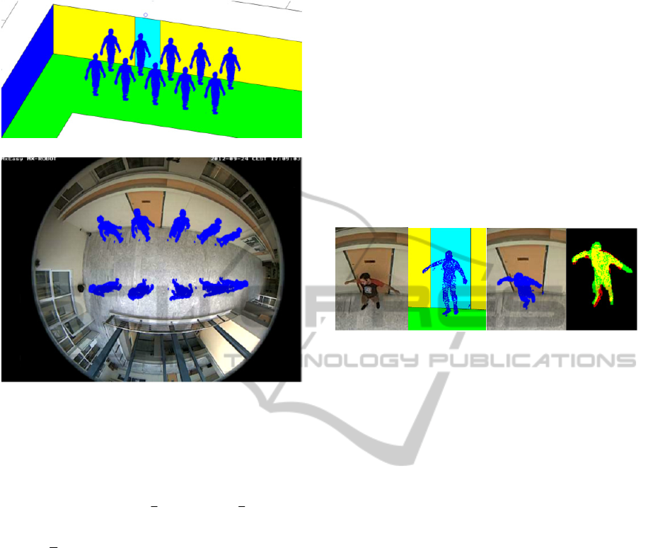
(a)
(b)
Figure 6: (a) scaling the model to height=1.8 m, touching
the floor and reproducing the model at several locations of
the imaged room and (b) rendering the 3D human models
through the calibrated fisheye lens.
The objective function is defined as following:
MS MS MS
image
domain
f IIIIII
m
p
(10)
where,
I denotes the boolean negative of I,
denotes the boolean AND operator and the
summation is done over the whole image domain.
The objective function is defined as the number of
non-zero pixels of I
M
on non-zero pixels of I
S
minus
the number of non-zero pixels of I
M
on zero pixels of
I
S
, minus the number of zero pixels of I
M
on non-
zero pixels of I
S
. Thus, the objective function should
be maximized.
Due to the large number of parameters and the
complexity of the objective function, which cannot
be written in closed form and its derivatives cannot
be analytically computed, we employed a simple
Genetic Algorithm as an optimizer. The simple GA
is a generational one, as described in (Goldberg
1999), it uses real encoding, one-point crossover, a
population of 80 chromosomes and it is allowed to
converge for a maximum number of 1000 function
evaluations. The probability of crossover and
mutation was set to 0.8 and 0.01 respectively. For
these initial results, the step of evolutionary
optimization is not performed in real time. In the
Discussion section, we provide details about
execution times as well as future work towards the
direction of near real time execution.
3 EXPERIMENTAL RESULTS
The video sequences used in this work were
acquired using the Mobotix Q24 hemispheric
camera, which was installed on the ceiling of the
imaged room. The pixilation of each frame is
480x640.
(a) (b) (c) (d)
Figure 7: (a) An original video frame showing a human,
(b) the 3D model with its parameters fitted to the
segmented original frame, (c) the fisheye-rendered 3D
model in a simulated frame and (d) the matching (yellow)
between the segmented human (green) and the fisheye-
rendered model (red).
Figure 7 shows results from a typical frame (a). The
recovered 3D human model is shown in (b) and the
rendered 3D human model using the fisheye model
is shown in (c). The fitting of the fisheye-rendered
parametric 3D human model to the segmented frame
is shown in Fig. 7(d), as following: segmented frame
in green, the fisheye rendered 3D human in red and
their intersection in yellow. It can be observed that
the proposed algorithm was able to detect the
specific human pose. Initial results were obtained by
testing the proposed algorithm in 5 video sequences
of 1500 – 2000 frames, of a walking or standing
human. In Fig. 8a, the resulting segmentation from a
number of frames is shown in a single composite
frame. The results of fitting the fisheye-rendered 3D
human model to the actual segmented human
silhouette using GAs-based optimization is shown in
(8b) (same colours as in Fig.(7)). In (8c) the
recovered 3D human models are shown in the real
world space. These experiments show that it is
feasible to extract the human pose from a significant
percentage the fisheye video frames, even imperfect
segmentation.
PoseRecognitioninIndoorEnvironmentsusingaFisheyeCameraandaParametricHumanModel
475
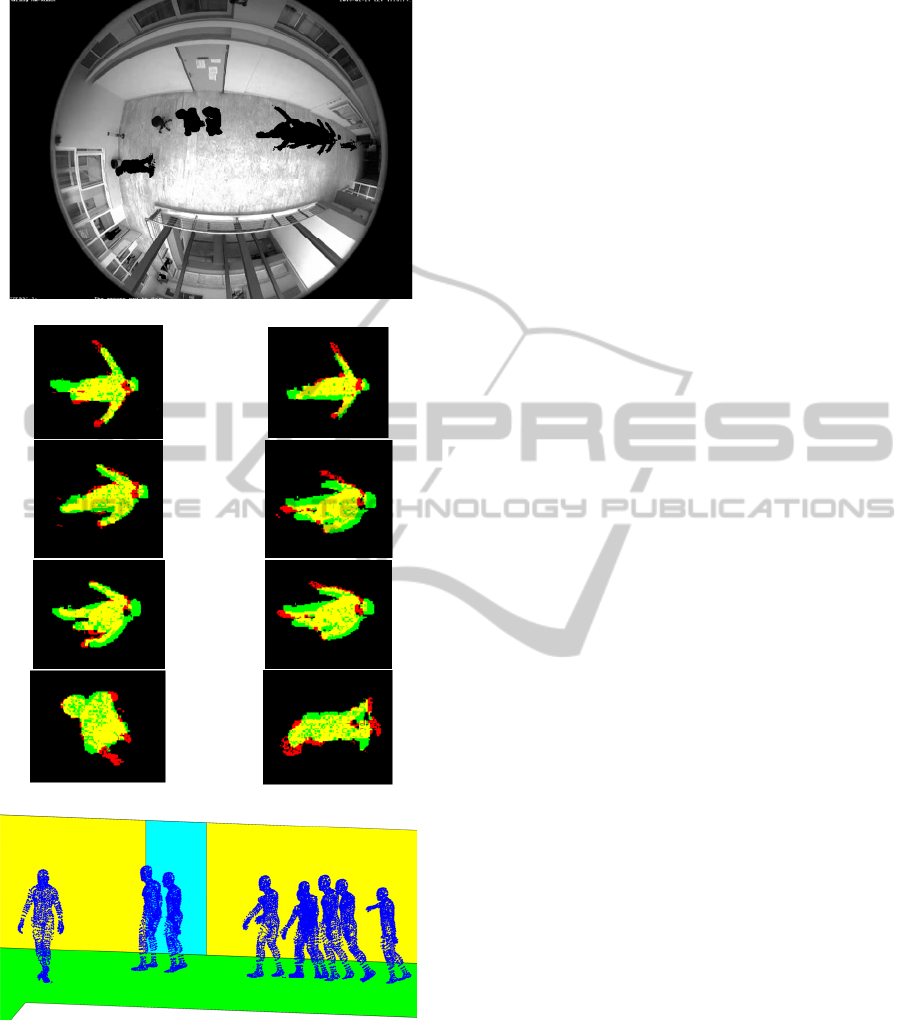
(a)
(b)
(c)
Figure 8: (a) a single composite frame the resulting
segmentation from a number of frames. (b) The fisheye-
rendered parametric 3D human models fitted to the
segmented frames (see text). (c) the recovered 3D human
models in the Cartesian space.
4 CONCLUSIONS
A methodology for human pose recognition has been
presented in this paper. The proposed algorithms are
based on a deformable 3D human model, a
parametric model of the specific fisheye camera and
a top-down approach using GAs-based optimization.
Given the video foreground segmentation refinement
and its geometry-based refinement, the algorithm
estimates the human’s position and pose,
considering the orientation of its limbs. Initial results
have been presented that show the feasibility of the
proposed methodology.
The generation of the 3D parametric human
model is performed in approximately 1 msec. The
rendering of a 3D human model with 2.500 vertices
through the modelled fisheye camera is also
performed in 1.5 msec. The calculation of the
objective function (Eq. 10) requires approx. 8 msec
for a 3D model with 2.500 vertices and a frame of
480x640 pixels. All timing was performed using an
Intel(R) Core i5-2430 CPU @ 2.40 GHz Laptop
with 4 GB Ram, under Windows 7 Home Premium.
The code was developed using the Matlab
programming environment. No special code
optimization or any kind of parallelization was
performed. It becomes clear that the optimization of
the objective function in order to extract the human
pose has not been performed in real time. At this
stage, these initial results serve as proof of concept
that the proposed algorithm is feasible. Further work
will include, the adoption of a more robust statistical
3D model for the human and the refinement of the
fisheye model, using more parameters to increase its
accuracy. Finally more efficient implementation of
the genetic algorithm based optimization will be
explored for the determination of the 3D model
parameters. These approaches include exploiting the
converged population from the previous frames to
initialize the search for the current frame and/or
restricting the parameter range according to their
optimal values from the previous frames.
ACKNOWLEDGEMENTS
The authors would like to thank the European Union
(European Social Fund ESF) and Greek national
funds through the Operational Program "Education
and Lifelong Learning" of the National Strategic
Reference Framework (NSRF) - Research
Funding
Program: \Thalis \ Interdisciplinary Research in
Affective Computing for Biological Activity
VISAPP2014-InternationalConferenceonComputerVisionTheoryandApplications
476

Recognition in Assistive Environments for
financially supporting this work.
REFERENCES
Willems J., Debard G., Bonroy B., Vanrumste B. and
Goedemé T., “How to detect human fall in video? An
overview”, In Proceedings of the positioning and
contex-awareness international conference (Antwerp,
Belgium, 28 May, 2009), POCA '09.
Cucchiara, R., Grana, C., Piccardi, M., and Prati A. 2003.
Detecting moving objects, ghosts, and shadows in
video streams. IEEE Transactions on Pattern Analysis
and Machine Intelligence 25, 10, (2003), 1337-1442.
McFarlane, N. and Schofield C., “Segmentation and
tracking of piglets in images”, MACH VISION APPL.
8, 3, (May. 1995), 187-193.
Wren, C., Azarhayejani, A., Darrell, T., and Pentland, A.
P. 1997. Pfinder: real-time tracking of the human
body, IEEE Transactions on Pattern Analysis and
Machine Intelligence 19, 7, (October. 1997), 780-785.
Stauffer C., and Grimson W., “Adaptive background
mixture models for real-time tracking”. In
Proceedings of the conference on computer vision and
pattern recognition (Ft. Collins, USA, June 23-25,
1999), CVPR '99. IEEE Computer Society, New York,
NY, pp. 246-252.
Cheng F. C., Huang S. C. and Ruan S. J. 2011,
Implementation of Illumination-Sensitive Background
Modeling Approach for Accurate Moving Object
Detection, IEEE Trans. on Boardcasting, vol. 57, no.
4, pp.794-801, 2011.
Christodoulidis A., Delibasis K., Maglogiannis I., “Near
real-time human silhouette and movement detection in
indoor environments using fixed cameras”, in The 5th
ACM International Conference on PErvasive
Technologies Related to Assistive Environments,
Heraklion, Crete, Greece, 2012.
Delamarre, Q., Faugeras, O., “3D articulated models
andmultiview tracking with physical forces”,
Computer Vision and ImageUnderstanding (CVIU) 81
(3) (2001) 328–357.
Kehl, R., Van Gool, L., “Markerless tracking of complex
human motions from multiple views”, Computer
Vision and Image Understanding (CVIU) 104 (2–3)
(2006) 190–209.
Barron, C., Kakadiaris, I., “Estimating anthropometryand
pose from a single uncalibrated image”, Computer
Vision andImage Understanding (CVIU) 81 (3) (2001)
269–284.
Bregler, C., Malik, J., Pullen, K., “Twist basedacquisition
and tracking of animal and human kinematics”,
International Journal of Computer Vision 56 (3)
(2004) 179–194.
Taylor, C., Reconstruction of articulated objects from
point correspondences in a single uncalibrated image,
Computer Vision and Image Understanding (CVIU)
80 (3) (2000) 349–363.
Liebowitz, D., Carlsson, S., “Uncalibrated motion
captureexploiting articulated structure constraints”,
International Journal of Computer Vision 51 (3)
(2003) 171–187.
Poppe, R., “Vision-based human motion analysis: An
overview”, Computer Vision and Image
Understanding, 108 (2007) 4–18.
Kemmotsu, K., Tomonaka, T., Shiotani, S., Koketsu, Y.,
and Iehara, M., "Recognizing human behaviors with
vision sensors in a Network Robot System," IEEE Int.
Conf on Robotics and Automation, pp.l274-1279,
2006.
Zhou, Z., Chen, X., Chung, Y., He, Z., Han, T. X. and
Keller, J., "Activity Analysis, Summarization and
Visualization for Indoor Human Activity Monitoring,"
IEEE Trans. on Circuit and systems for Video
Technology, Vol. 18, No. II, pp. 1489-1498,2008.
M. Saito and K. Kitaguchi, G. Kimura and M.
Hashimoto,“Human Detection from Fish-eye Image by
Bayesian Combination of Probabilistic Appearance
Models”, IEEE International Conference on Systems
Man and Cybernetics (SMC), 2010, pp243-248.
Li H. and Hartley R., “Plane-Based Calibration and Auto-
calibration of a Fish-Eye” Camera, P.J. Narayanan et
al. (Eds.): ACCV 2006, LNCS 3851, pp. 21–30, 2006,
c Springer-Verlag Berlin Heidelberg 2006.
Basu A., Licardie S., “Modeling fish-eye lenses”,
Proceedings of the 1993 IEEWSJ International
Conference on Intelligent Robots and Systems
Yokohama, Japan July 2630,1993.
Shah S. and Aggarwal J., “Intrinsic parameter calibration
procedure for a high distortion fish-eye lens camera
with distortion model and accuracy estimation”,
Pattern Recognition 29(11), 1775- 1788, 1996.
Delibasis K. K., Goudas T., Plagianakos V. P. and
Maglogiannis I., Fisheye Camera Modeling for
Human Segmentation Refinement in Indoor Videos, in
The 6th ACM International Conference on PErvasive
Technologies Related to Assistive Environments,
PETRA 2013.
Max, N., “Computer Graphics Distortion for IMAX and
OMNIMAX Projection”, Proc Nicograph 83, Dec
1983 pp 137.
Greene, N., “Environment Mapping and Other
Applications of World Projections”, IEEE Computer
Graphics and Applications, November 1986, vol.
6(11), pp 21.
http://paulbourke.net/dome/fisheye/
Micusik, B. and Pajdla, T., “Structure from Motion with
Wide Circular Field of View Cameras”, IEEE
Transactions on Pattern Analysis and Machine
Intelligence, PAMI 28(7), 2006, pp. 1-15.
http://www.3dmodelfree.com/models/20966-0.htm.
Goldberg D., “Genetic Algorithms in Search,
Optimization, and Machine Learning”, Addison
Wesley, 1989.
PoseRecognitioninIndoorEnvironmentsusingaFisheyeCameraandaParametricHumanModel
477
