
Hand Veins Recognition System
João Ricardo Gonçalves Neves and Paulo Lobato Correia
Instituto de Telecomunicações, Instituto Superior Técnico, Av. Rovisco Pais, Lisbon, Portugal
Keywords: Hand based Biometrics, Biometrics Recognition, Palm Veins, Hand Geometry, Palm Veins, Acquisition
System, Palmprint, Web-cam.
Abstract: Accurate protection systems capable of replacing the traditional passwords and ID cards are essential, for
commodity and for security reasons. A hand-vein pattern recognition system is just one of a vast group of
biometrics techniques under research, in order to become the reference recognition system. This paper
presents a hand vein biometric recognition system that uses the hand blood vessels pattern to identify an
individual. All biometric systems have an immense application potential as they present advantages over the
traditional identification systems. They are able to work with patterns that are very hard to duplicate, since
they are different from person to person, and it is also impossible to lose of forget them, since the biometric
characteristics are intrinsically attached to the human body. The developed approach was created with the
intent of providing an effective protection system despite having been designed and implemented using
inexpensive hardware, in comparison with the biometric recognition systems presently offered at a
commercial level. The results show that a reliable system can be produced at a low cost and can be used
standalone or in combination with other systems.
1 INTRODUCTION
Nowadays, we can access our personal data from
almost everywhere. This is very convenient but
entails increasing risks since the probability of
phishing credentials increases with the number of
users. More sophisticated protection systems are
required to control possible harassments, like ID
cards cloning, theft or compromised passwords.
When thinking about digital protection, one
which immediately comes to mind is the use of
passwords and smart cards, since they are used daily
for almost everything. Despite being used very
frequently, passwords and smart cards are a
relatively insecure method of protection and access
control.
The biometric systems experienced a significant
growth in the recent years, both at research and
commercial level, pushed by the need for innovative
and improved ways to protect our personal
information.
The field of biometrics recognition deals with the
identification of a human by using its distinctive
traits. They can be categorized in two major groups,
behavioral and physiological.
The behavioral traits are related to the user
behavior and include the signature or gait. The
physiological traits include personal characteristics
like hand geometry, fingerprints, ear or face.
Biometric systems that analyze traits like the
finger veins, fingerprint or iris, are nowadays mostly
used as a form of recognition. Those systems are
widely used to control the access to certain
applications, private areas or even in forensic
scenarios. The majority of the systems available
provide real time automatic solutions which extract a
human feature, then compute a template and
compare it with the ones previously stored in a
database to provide a matching decision.
2 DIFFERENT BIOMETRIC
RECOGNITION SYSTEMS
There are several approaches that exploit the hand
biometric characteristics to identify an individual.
Huan Zhang and Dewen (Zhang, 2010) on theirs
hand vein recognition system achieved an EER of
1.82% with an AD-080CL camera that costs around
3000€.
Mauricio Ramalho (Ramalho, 2010) in his
palmprint recognition system used an operating
122
Ricardo Gonçalves Neves J. and Lobato Correia P..
Hand Veins Recognition System.
DOI: 10.5220/0004688701220129
In Proceedings of the 9th International Conference on Computer Vision Theory and Applications (VISAPP-2014), pages 122-129
ISBN: 978-989-758-003-1
Copyright
c
2014 SCITEPRESS (Science and Technology Publications, Lda.)

Pre‐processing
Image
Acquisition
Access
Granted
Valid
Yes/No
Feature
Extraction
Matching
Valid
Yes/No
AccessDenied
Binary
Templates
Database
Register
Register
Yes/No
Figure 1: Developed system architecture.
point that achieves 9.5% for the False Reject Rate
(FRR), 0.1% for False Accept Rate (FAR) and
3.29% for the Equal Error Rate (EER) using an
expensive camera.
Nuno Moço (Moço, 2012) in his palmprint
recognition system for cellphones used an operating
point that achieved 9.87% of FRR and 0.03% of
FAR with an EER of around 5%.
Table 1: Prices and cameras of different researchers.
Author Camera Cost(€)
João Neves
Logitech
QuickCam
Pro 9000
20
Huan Zhang AD-080CL 3000
Maurício
Ramalho
Olympus C-
3020
400
Nuno Moço HTC Desire 550
3 PROPOSED HAND VEIN
RECOGNITION SYSTEM
The proposed biometric recognition system is
unimodal and uses the hand vein pattern as the
biometric trait. The architecture of the developed
system is presented in Figure 1. It includes the
following main modules: image acquisition, pre-
processing, feature extraction, matching and
decision.
The following paragraph gives a summarized
description of the approaches taken.
To do the image acquisition in the developed
system a modified low cost camera is used. After the
image acquisition the captured image is resized in
order to reduce the required computational power,
turning the pre-processing less demanding and
consequently saving processing time. After resizing
the acquired image, is preprocessed in order to
reduce the amount of noise. The detection of the
region of interest is obtained through some reference
points in the hand contour. The feature extraction
and template creation sections are based on the
Orthogonal Line Ordinal Features (OLOF) (Sun,
2005) technique. The OLOF method turns the veins
representation robust against illumination variations.
It also makes the matching stage effortless since the
dissimilarities between two palmprints can be
measured through the differences in the binary bits
from the two templates with a simple XOR operator,
which can be computed almost instantly.
3.1 Image Acquisition
Since the system performs recognition based on vein
images, the illumination is obtained using 15 near IR
leds (OSRAM – SFH4550), see Figure 2.
Figure 2: IR illumination.
The box is a cube with 26 cm side. The top of the
box was painted black in order to reduce the
interference instigated by the visible light coming
from the exterior of the assembly, Figure 3.
HandVeinsRecognitionSystem
123
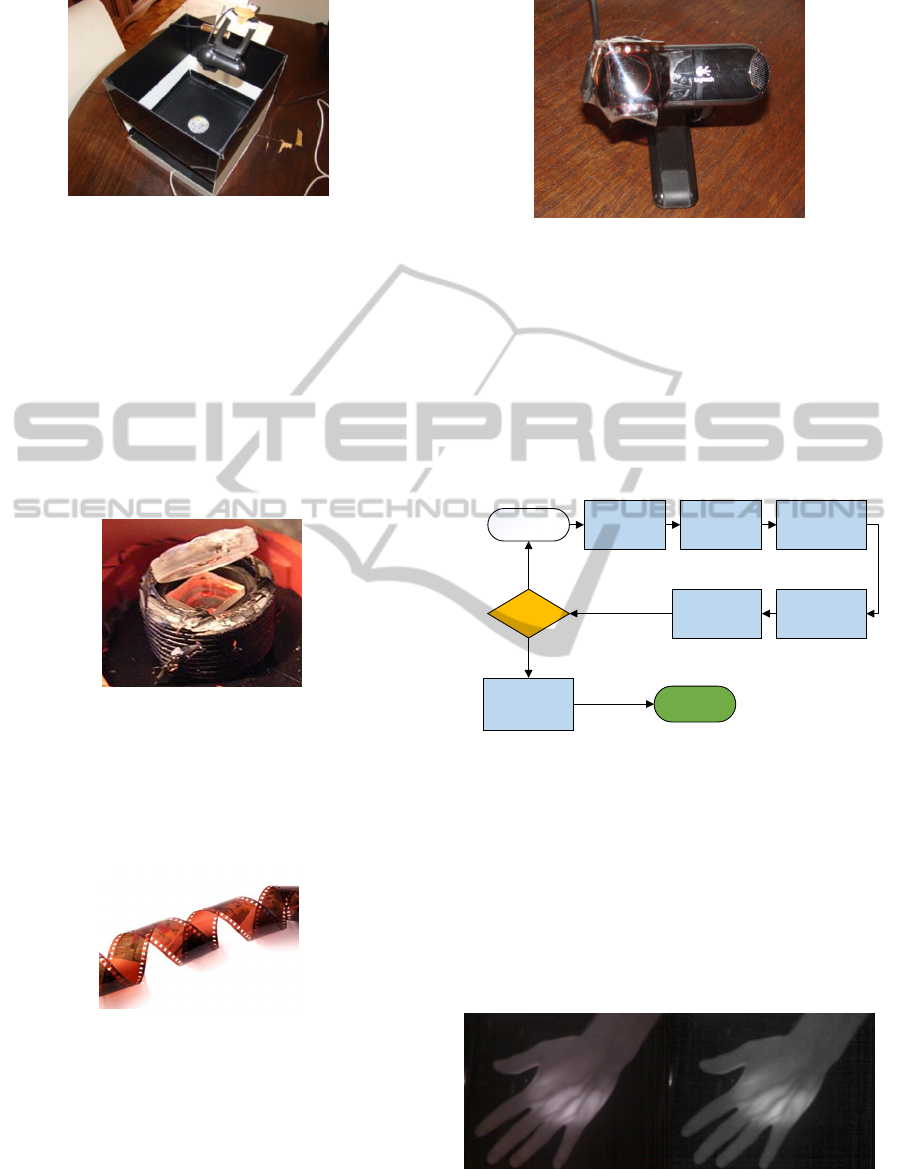
Figure 3: Developed System.
In order to be able to capture the near infrared light,
necessary for the vein acquisition, the low cost web-
camera requires the removal of the infrared filter
that is placed behind the lens, as illustrated in Figure
4. The main problem associated with the removal of
the IR filter is that the auto-focus functionality of the
web-camera becomes damaged, which turns the
capture of good quality images at long distances
impossible. This problem won’t affect the image
acquisitions of the developed system since they are
captured from a small distance.
Figure 4: Square Infrared filter that needs to be removed in
order for the webcam to capture infrared images.
As the camera needs to detect only infrared light, a
visible filter has been applied. An old fashioned
photographic revealed film was used for this
purpose, as shown in Figure 5.
Figure 5: Photographic film used to filter out visible light.
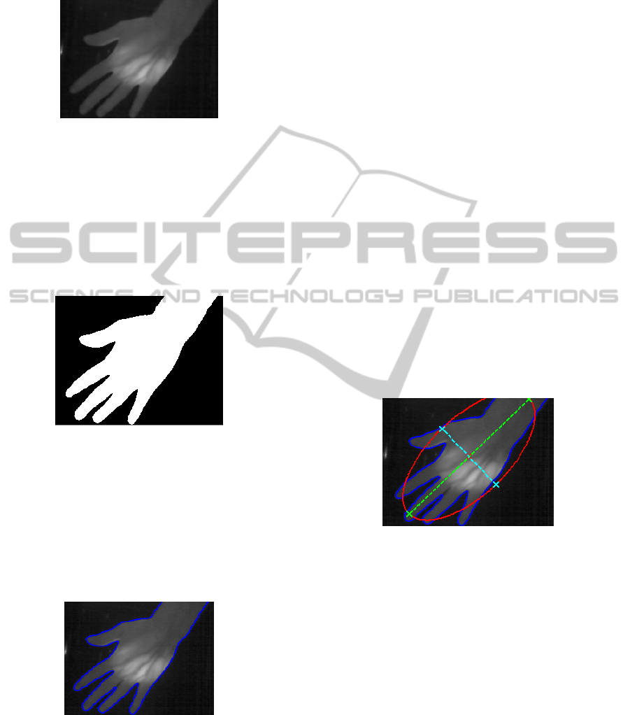
After removing the IR filter in the back of the lens
and assembling the visible light filter in front of it,
the camera is ready to do the acquisition of near
infrared images, Figure 6.
Figure 6: Modified web camera used to do hand veins
acquisition.
3.2 Pre-processing
The pre-processing stage prepares the image for the
feature extraction phase. This is obtained through
several stages: image adjustment, filtering,
segmentation, contour detection, key point’s
detection and region of interest extraction, as
represented in the architecture illustrated in Figure 7.
Image
Adjustment
ImageFiltering
Image
Segmentation
RawImage
ROI
Acquisition
Valid?
KeyPoints
Discovery
Contour
Detection
Regionof
Interest
Extraction
No
Yes
Figure 7: Developed pre-processing stages.
The first step of the pre-processing stage is image
adjustment. During this step the raw image is resized
from 240x320 to 192X256, in order to reduce the
computational power required through the process.
After resizing the raw image, the color space is
converted from rgb to grayscale since the luminance
information is enough for the image segmentation,
see Figure 8.
Figure 8: Raw image and image after adjustment step.
The second step of the pre-processing chain is the
VISAPP2014-InternationalConferenceonComputerVisionTheoryandApplications
124
filtering, used to reduce the noise of the image and
to smooth the areas with little variance. This is
obtained using a Wiener filter, seen Figure 9.
Figure 9: Image smoothed by a Wiener filter.
The third module performs image segmentation,
where the image is segmented into foreground and
background through a pre-defined threshold.
Thresholding is a very fast way of identifying the
hand using the contrast with the black background.
After thresholding the image it is converted to
binary. One example of a segmented image obtained
is depicted in Figure 10.
Figure 10: Image segmented in foreground and
background.
The segmented image is the input of the contour
detection algorithm (Shapiro, 2000). This algorithm
choses a random starting point in the hand boundary
and then searches for all the boundary pixels. The
contour is essential for identifying the region of
interest and the reference points. The hand contour
can be seen in the Figure 11.
Figure 11: Hand contour.
The key point’s acquisitions are obtained through
the combination of two different techniques, the
radial distance to a fixed point and the contour
curvegram. Both methods identify the fingertips and
the valleys between the fingers.
The radial distance to a fixed point technique
calculates the Euclidean distance between every
contour pixel and a fixed point, which is the middle
point of the region where the wrist crosses the image
edge.
The contour curvegram analyzes the intensity of
the curvature along the contour, and can be
constructed by using a technique called difference-
of-slopes (Konukoglum, 2006).
The two methods have their benefits and
drawbacks, but together they create a stronger set of
reference points. The radial distance to a fixed point
is the first technique used in order to get an
approximation of the final reference points. After
obtaining the raw key points, the contour curvegram
is used around the obtained locations. The final
obtained positions are the final fingertip and finger-
valley locations.
In order to obtain a good location of the fixed
point, to be used in the radial distance method, an
ellipse (Figure 12) with the same normalized second
central moment as the hand region is drawn.
Through the hand contour input, the ellipse’s
parameters like the major and minor axes, center
position, end-points and lengths, orientation (given
by the angle between the major and minor axes) are
calculated.
Figure 12: Ellipse with the same normalized second
central moment as the hand region.
After obtaining the parameters that define the
ellipse, it is necessary to find out in which side of
the minor axis the wrist is located. This verification
is obtained through the counting of the contour
points that lie on each side of the axis. The wrist is
located on the side with fewer points. Knowing the
axis’ side on which the wrist lies, the fixed point
(Figure 13) in the wrist is defined as the intersection
point between the major axis and the edge of the
image.
The additional reference points, represented as
yellow dots in the Figure 14, are necessary to extract
the palm’s region of interest. These additional
reference points are determined by discovering, the
thumb, index and pinkie fingers.
HandVeinsRecognitionSystem
125
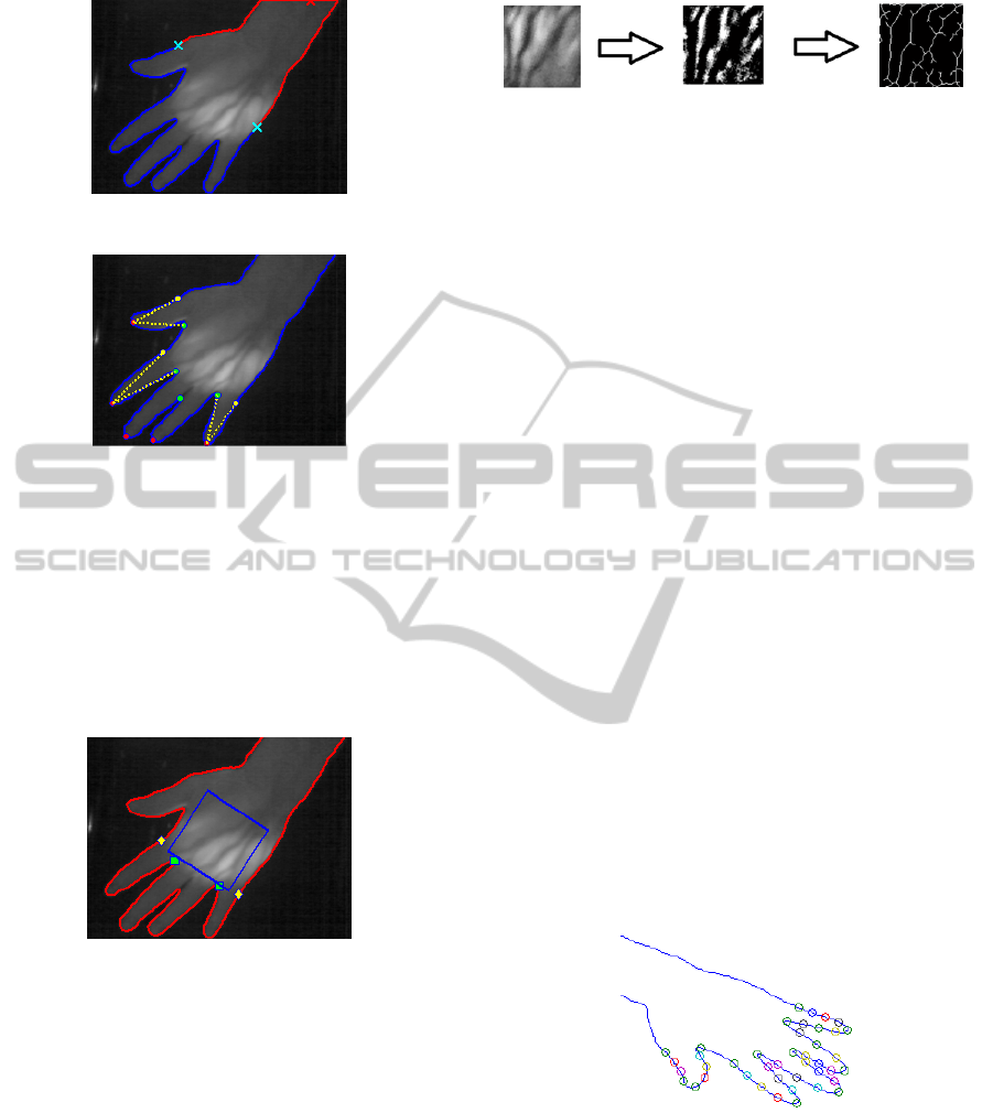
Figure 13: Fixed point marked as the half red cross.
Figure 14: Hand reference points.
The final set of hand reference points, is composed
by the five fingertips, the four finger valley and the
three additional reference points.
After finding the reference points, the square that
represents the ROI is obtained, Figure 15. The
square position is defined through a line segment
that is drawn between the index and the pinkie
finger.
Figure 15: Region of interest acquisition.
Different hands will create squares with different
sizes and orientations that will need to be
normalized for matching purposes. In order to do the
standardization the ROI is rotated to a vertical
position and resized to a standard dimension. The
standard ROI dimension chosen is 128x128 due to
the results that will be presented in the performance
evaluation section. Decreasing the dimensions
would reduce the computational effort but would
also reduce the detail of the image.
After the rotating step the image is binarized and
filtered and then a thinning method is applied in
order to thin and repair the vein line. The ROI
treatment step can be seen in the Figure 16.
After being thinned the standardized ROI is
Figure 16: ROI treatment steps.
converted into a vector consisting in luminance
values.
Through the reference points illustrated on
Figure 17, the value of 35 hand geometry
characteristics will be calculated in order to provide
the geometrical information of the hand. The
characteristics used are the finger widths (20),
perimeters (5) and lengths (10). After acquiring the
35 hand geometry characteristics, a mean of the 35
values is calculated. This mean summarizes the
geometrical information of the hand, so each user in
the database will have one mean associated. At the
identification stage, the mean of the recently
acquired template under identification will be
compared with the remaining geometrical
information (means) of the previously acquired data
in the database. Instead of comparing templates
randomly, the most probable will be compared first.
The most probable users will be the ones that
have similar hand geometry. If the vein pattern
under identification does not fit the one from the
user with the most similar geometry, the algorithm
searches the next most similar and so on, until
finding the one with the same vein pattern. The
delay obtained by calculating the hand geometry
characteristics is almost irrelevant, due to the simple
calculations required.
The geometry similarity is not crucial for a
positive matching, but helps sorting the most
probable hands.
Figure 17: Reference points used to calculate the hand
geometry characteristics values.
3.3 Feature Extraction
The feature extraction module will output the
biometric template, which will be used in the
matching stage. The feature extraction technique
used in the developed system is the Orthogonal Line
Ordinal Features (OLOF)0.
VISAPP2014-InternationalConferenceonComputerVisionTheoryandApplications
126

The one-dimension vector obtained in the pre-
processing module will be the input of the OLOF
method that will generate a one bit feature code that
is going to be the template stored in the database.
The OLOF approach uses a 2D Gaussian
filter to acquire the weighted average intensity
of a line-like region, equation(1) (Sun,2005).
,,
(1)
In equation (1), symbolizes the orientation of the
2D Gaussian filter,
the filter’s horizontal scale
and
the filter’s vertical scale.
Equation (2) represents the orthogonal line ordinal
filter, designed to compare two orthogonal line-like
palmprint image orientations for the same region
(Sun, 2005).
,,
,,
2
(2)
The filtering of the ROI is accomplished using three
orthogonal line ordinal filters through three different
orientations (θ), in this case: OF (0), OF (
) and OF
(
). The filter parameters used were
9 and
3. The filter is centered at
,
17,17
0.
The output of the feature extraction phase using
the OLOF extraction method are three bit ordinal
codes based on the sign of the filtering results from
equation(2) , (Figure 18).
Figure 18: OLOF output in three directions,
,
and.
3.4 Matching System
A successful or unsuccessful recognition of an
individual is based on the calculation of the bitwise
Hamming distances of the recently acquired
template and all the others in the database. The
Hamming distance between two vectors is the
number of coefficients in which the corresponding
symbols differ. If two vectors are exactly equal the
Hamming distance will be zero. To calculate the
Hamming distance a bitwise XOR operator is used.
The validation or refusal of the matching is defined
by a predefined threshold.
4 EXPERIMENTAL RESULTS
The experimental results of the developed biometric
system are evaluated by the Receiver Operation
Characteristic (ROC) curve which plots the FAR
against the Genuine Accept Rate (GAR) (or 1-FRR)
and by the Equal Error Rate (EER), which is defined
as the error rate when the FAR and the FRR are
equal.
A recognition attempt might have the results
presented in Table 2.
Table 2: Possible recognition attempts results.
Type of
user
Match Non-Match
Genuine
Correct
Accept
False Reject
Impostor False Accept
Correct
Reject
4.1 Test Conditions
In order to test the performance of the developed
system, the first step was to create a hand palm vein
database containing 30 registered people. For each
person, five different acquisitions from each hand
were performed. For the testing purposes each hand
is considered as a different user. 30 registered people
represent 300 different templates.
4.2 Performance Evaluation
The system performance was tested using the
database mentioned above, using a ROI size of
128x128 and the features were extracted with the
OLOF technique.
The obtained ROC curve is shown in the Figure
.The ROC curve is near the perfect point (0,100)
which shows the good matching performance of the
system.
The ROC curve and the table show that GAR is
near 85% when the FAR is 0%.
For applications like opening doors for non-high
secure areas values of FAR above 0% can be used
despite the slope suggesting that there is no benefit
on using an operating point that has a GAR above
85%.
For ATM machine operations the FAR must be
around 0% so values of GAR around the 85% or
inferior are mandatory.
An alternative way of evaluating the
performance of a biometric system is through the
EER. A low EER means that is possible to get both
HandVeinsRecognitionSystem
127
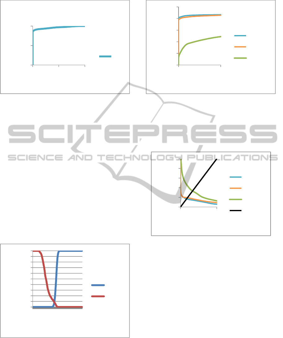
Figure 19: Receiver Operation Characteristic curve for a
ROI with 128x128 pixels.
low values of FRR and of FAR and thus the lower
the EER, the better the performance is. Despite
being a good reference point, the EER might not be
the ideal operating point for a given system. The
system might require a lower FRR or FAR for
special application conditions. A system that
requires high security conditions like the ATM
machine will require a really low FAR which will
possibly imply a higher FRR.
Figure 20 shows the FAR and FRR curves
produced as functions of the threshold. The figure
shows that when the threshold value increases the
FRR decreases and the FAR increases. The figure
also shows that if the threshold is lower that 40% the
FAR is near zero. Through the figure it is perceptive
that the EER of the developed system is near 9% and
the associated threshold is about 45%.
Figure 20: FAR and FRR at different operating thresholds.
In order to test which ROI size should be used, three
ROC curve were created. The three sizes tested
were, 32x32, 64x64 and 128x128 pixels. The
obtained result is depicted in the Figure 21.
Figure 21: ROC curve for different ROI dimensions.
From the Figure 21 is obvious that the ROI size of
128x128 pixels and 64x64 obtain the best results in
terms of matching. The ROI size of 32x32 pixels
clearly underperforms both in the ROC curve as well
in the EER (see Figure 22).
Figure 22: FRR (%) against FAR (%) to obtain EER for
different ROI dimensions.
The ROI size chosen was 128x128 pixels due to the
better matching performance.
4.3 Operating Point
The operating point used depends on the application.
It must be chosen taking into account the system
recognition performance and his security. The
developed system can be used on several
applications, like ATM machine operations, opening
doors or even to unlock a computer. The operating
points obtained with the developed system are
present in the Table 3.
0
50
100
050100
GAR(%)
FAR(%)
ROC
ROC
0
10
20
30
40
50
60
70
80
90
100
0
10
20
30
40
50
60
70
80
90
100
%
Threshold(%)
FAR(%)
FRR(%)
0
20
40
60
80
100
00,5
GAR(%)
FAR(%)
128x128
64x64
32x32
0
10
20
30
40
50
050
FRR(%)
FAR(%)
128x128
64x64
32x32
EER
VISAPP2014-InternationalConferenceonComputerVisionTheoryandApplications
128

Table 3: Values of FAR and FRR for different operating
points.
Threshold(%) FAR(%) FRR(%)
35 0.000 19.667
35.5 0.002 18.833
36 0.009 18.167
36.5 0.011 18.000
37 0.020 17.500
37,5 0.038 16.167
38 0.072 15.167
38.5 0.113 14.667
39 0.199 14.000
39.5 0.337 13.833
40 0.508 13.333
5 CONCLUSIONS
This paper presents a unimodal biometric
recognition system that used the hand vein patterns
to do the identification of an individual. It was
developed in Matlab and implemented to work on a
Windows operation system.
The developed system has proved to have several
operating points that can be used in different
scenarios. In addition it has the advantage of being a
low-cost, requiring an investment around 50€, and is
simple to assemble.
The EER of the developed system is near 9%,
The ROI dimension used is 128x128 pixels due to
the best matching results during the tests. The OLOF
templates dimensions used is 32x32.
ACKNOWLEDGEMENTS
The authors acknowledge the support from
Fundação para a Ciência e Tecnologia (FCT) and
Instituto de Telecomunicações, under project PEst-
OE/EEI/0008/2013.
REFERENCES
Zhang, H. & Hu, D., 2010, “A Palm Vein Recognition
System”, IEEE Proceedings of the International
Conference on Intelligent Computation Technology
and Automation, pp.285-288.
Ramalho, M., 2010, “Secure Palmprint Verification
System”, Master Degree Dissertation, Instituto
Superior Técnico, Lisboa.
Moço, N., 2012, “Biometric Recognition Based on
Smartphone”, 2012, Master Degree Dissertation,
Instituto Superior Técnico, Lisboa.
Sun, Z., Tan, T., Wang, Y., 2005, “Ordinal Palmprint
Representation for Personal Identification”, IEEE
Proceedings of the Computer Vision and Pattern
Recognition, 1, pp.279-284.
Shapiro, L. & Stockman, G., 2000, “Computer Vision”,
Prentice Hall, Upper Saddle River, N.J.
Konukoglum, E., Yorukm, E., Darbon, J. & Sankurm, B.,
2006, “Shape-Based Hand Recognition”, IEEE
Transactions on Image Processing, 15 (7), pp.1803-
1815.
HandVeinsRecognitionSystem
129
