
Feature Evaluation and Management
for Camera Pose Tracking on 3D Models
Martin Schumann, Jan Hoppenheit and Stefan M
¨
uller
Institute of Computational Visualistics, University of Koblenz, Koblenz, Germany
Keywords:
Camera, Pose, Tracking, Model, Feature, Evaluation, Management.
Abstract:
Our tracking approach uses feature evaluation and management to estimate the camera pose on the camera
image and a given geometric model. The aim is to gain a minimal but qualitative set of 2D image line and 3D
model edge correspondences to improve accuracy and computation time. Reducing the amount of feature data
makes it possible to use any complex model for tracking. Additionally, the presence of a 3D model delivers
useful information to predict reliable features which can be matched in the camera image with high probability
avoiding possible false matches. Therefore, a quality measure is defined to evaluate and select features best
fitted for tracking upon criteria from rendering process and knowledge about the environment like geometry
and topology, perspective projection, light and matching success feedback. We test the feature management to
analyze the importance and influence of each quality criterion on the tracking and to find an optimal weighting.
1 INTRODUCTION
Many approaches in markerless tracking derive the
pose of the camera - the viewing position and ori-
entation - by using corresponding 2D-2D features in
succeeding frames of the video input. Regarding im-
age information only for detection and description of
features, correspondences become ambiguous. Dis-
turbing lighting conditions and occlusion may cause
unstable results. Further, sequential frame-to-frame
tracking is prone to accumulate detection and match-
ing errors which leads to drift in the camera pose.
In model-based tracking the scene is represented
by 3D data which can be available from a modeling
process or is created online while tracking. The cam-
era pose is derived from minimization of the distance
error between the projections of the 3D model fea-
tures and strong gradients in the image representing
their 2D correspondences. Tracking on a CAD model
was shown by (Comport et al., 2003) describing com-
plex structures of the tracked object. Respectable suc-
cess in tracking a line model in combination with
point features could be demonstrated by (Vacchetti
et al., 2004) and (Wuest and Stricker, 2007) used the
depth buffer to extract contour lines of a 3D model
for tracking. Recently, (Oikawa et al., 2012) applied
local quadric approximations of the object contour to
minimize the distance between model and camera im-
age.
The benefit of a 3D model is the additional in-
formation which can be used to predict image fea-
tures suitable for robust tracking. In the ”analysis-by-
synthesis” approach, a synthetic image of the given
model is rendered as a reference to the camera image,
based on the last verified camera pose. The properties
of model, camera and real environment are used as
quality criteria for selecting only the most stable fea-
tures in every frame. The idea is a feature manager
that creates a feature list with annotated descriptor
vectors defining a quality measure to evaluate the fea-
tures. Selecting a minimal but qualitative set of fea-
tures not only reduces computation time significantly,
but may also improve the tracking accuracy by filter-
ing unstable features leading to bad correspondences.
Management of point features has been done
successfully on sequential frame-to-frame tracking
by (Shi and Tomasi, 1994). The quality of image fea-
tures is evaluated regarding the change of the feature
appearance in the image and by detection of occlu-
sions and noise. The feature in the current frame is
compared to its first detection in the sequence. A
high dissimilarity shows that the feature has under-
gone a strong change which leads to a discard of the
feature. However, the quality of the features is only
judged by image intensities as most feature detec-
tors do. Another approach to select optimal image
features is shown in (Collins et al., 2005). The fea-
tures are evaluated and ranked based on their qual-
562
Schumann M., Hoppenheit J. and Müller S..
Feature Evaluation and Management for Camera Pose Tracking on 3D Models.
DOI: 10.5220/0004685905620569
In Proceedings of the 9th International Conference on Computer Vision Theory and Applications (VISAPP-2014), pages 562-569
ISBN: 978-989-758-009-3
Copyright
c
2014 SCITEPRESS (Science and Technology Publications, Lda.)
3D-Model Camera Image
Geometry List +
Quality Descriptor
with History
Initial geometry
preprocessing
Feedback
Pose
Estimator selects
Features
Rendering
Projection
Matching
Rendered Image
Light + Material
Information
Camera pose
1
2
3
Update
Visibility Test
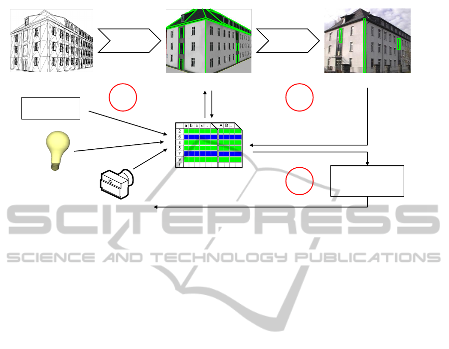
Figure 1: Feature management: Initial preprocessing of the 3D model data creates a geometry list. 1. Each feature is annotated
by a quality descriptor vector. A weighted quality value is calculated and a subset of the geometry is selected for the following
visibility test. 2. The matcher gives feedback about the matching result for the projected geometry. A refined quality value is
calculated. 3. The pose estimator selects the best features from the ranked input list.
ity to discriminate between object and background.
In (Wuest et al., 2007) features are managed regarding
their tracking probability from certain reconstructed
camera positions. Only those features will be used
which are likely to be visible from a given camera po-
sition. Features without valid reconstructed camera
position are removed. A confidence measure based on
texture analysis is proposed by (Steffens et al., 2009)
for stereo matching. Here, false correspondences are
reduced by prediction of regions reliable for match-
ing. Further, (Choi and Christensen, 2010) identify
sharp edge features using the face-normal information
of a model in a combined edge and keypoint tracking
framework.
2 FEATURE EVALUATION AND
MANAGEMENT
2.1 Overview
Unmanaged markerless tracking without quality eval-
uation usually considers all features detected in an
image for pose estimation. It is assumed that us-
ing a high count of features delivers enough good
correspondences to reduce the influence of erroneous
matches. This may lead to inaccuracies and to higher
computational load. In the presence of a model, the
additional knowledge of geometry and environment
can be used to identify suitable features which re-
duces the amount of data and may lead to a higher
quality of the correspondences.
Figure 1 gives an overview of the feature manage-
ment. The 3D model holds the complete geometry
data as a wireframe of edges. After initial preprocess-
ing a geometry list of model edge features is built. In
the first step each feature in the geometry list is anno-
tated by a quality descriptor vector defining a measure
for evaluation. The descriptor contains quality criteria
of model and camera-dependent information, as well
as light and material input and additionally holds a
history value that describes the evolution of the fea-
ture quality over the last frames. The values are in the
range [0,1] or have binary values - e.g. a feature can
be a silhouette (= 1) or it is not (= 0). From all in-
formation collected, a combined quality value in the
range of [0, 1] is calculated for each feature, where 1.0
denotes the best quality.
In the second step, a filtered subset of the geome-
try holding a minimum quality is rendered from the
current camera pose and the geometry features are
checked for visibility. The list of visible geometry
together with the annotated descriptors is sent to the
matcher. 2D image correspondences are detected and
feedback about the matching result is given to the de-
scriptor to refine the quality value of each edge. The
history value is updated and the pose estimator now
selects the best features from the resulting ranked in-
put list for estimation of the new pose. Defining a
value from several quality criteria makes it possible
to dynamically rank the features, so the pose estima-
FeatureEvaluationandManagementforCameraPoseTrackingon3DModels
563
tor can request features with highest priority. If there
are not enough features for successful pose estima-
tion, features of lower priority can be added. In the
following sections we describe the criteria for defin-
ing the quality descriptor in detail.
2.2 Preprocessing
When loading the model, an enhanced winged-edge
list is built, containing the whole wireframe informa-
tion with access to neighboring faces of each edge. If
both faces are planar or the connecting angle is below
a threshold, the edge will have no or only weak dif-
ferences of intensity under lighting and thus may hard
to be recognized by image processing. Regarding the
orientation of the neighboring faces by the angle be-
tween the face normals, edges connecting flat areas
can be removed from the wireframe for simplification
of the model data. Additionally, line segments with
common start and end points aligned in equal direc-
tion are merged to one edge feature forming a straight
visible line. Merging reduces the amount of data and
the computational load accordingly.
Further, parallelism is tested by comparing the
direction of the geometry edges. Parallel ones, i.e.
the dot product is approximately 1.0 or −1.0, are as-
signed to a common group. This is neccessary for
later quality evaluation of the distance. In preparation
of the visibility test and hidden line removal, a list of
possible occluders is defined for all edges. The faces
of the model are assigned unique material colors in
the red channel. Each edge now holds a list of colors
for all faces not connected to this edge, since these
faces may cause an occlusion. Optionally, thinning
the model may be reasonable when it is very detailed,
e.g. the windows consist of more geometry than the
visible outline (Fig. 2). Therefore, very short and par-
allel edges can be removed to lower the redundancy
in the data structure. The remaining features after the
initial face angle test and merging are saved in the ge-
ometry list.
2.3 Visibility Test
For every frame each edge in the preprocessed geom-
etry list is first tested for the orientation of its neigh-
boring faces in relation to the camera. Edges connect-
ing backfaces are not regarded for the current frame.
Second, all edges connecting two frontfacing poly-
gons or one front- and one backfacing polygon are
checked for occlusions. This is done by rendering the
faces with the material color into a color-index tex-
ture. From the preprocessing step a list of possible
occluders is known for each edge. The edges are pro-
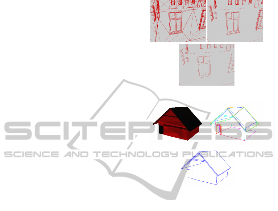
Figure 2: Model preprocessing. Top: Full wireframe (left)
and after face test (right). Bottom: Result after thinning.
Figure 3: Visibility test. Top: Color-index texture (left)
and preprocessed edges (right). Bottom: Resulting visible
edges.
jected and for the pixel positions along the resulting
image line, the color is read from the index texture. If
the retrieved color is not in the list of occluders, a vis-
ibility count for the edge is incremented. An edge is
considered visible when at least a minimal resolution-
dependent number of pixels is not occluded (Fig. 3).
2.4 Distance
Feature edges with small distance in world or image
space are difficult to distinguish when they are paral-
lel and may lead to erroneous correspondences while
matching. The quality value of such edges should be
decreased. Again, this criterion can be defined as per-
spectively dependent distance in relation to the cam-
era position. All edges that have been assigned to one
common group of parallel edges in the preprocessing
step are now checked for their distance. This is done
by defining the two planes spanned between the 3D
edges and the camera center (Fig. 4). The cross prod-
ucts between the vectors from the start points s
1
, s
2
of the edges to the camera center C, and the direc-
tion vectors of the edges result in the normal vectors
n
1
, n
2
of the planes. The angle between both plane
VISAPP2014-InternationalConferenceonComputerVisionTheoryandApplications
564
α
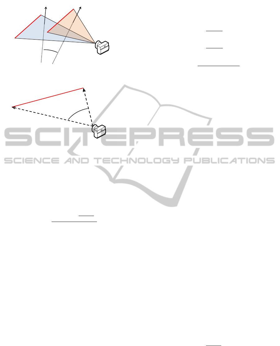
Figure 4: Distance measured by angle between edge-
camera planes.
α
Figure 5: Length measured by camera angle between start
and end point.
normals corresponds to the angular aperture of both
planes from the camera view and is stored as distance
quality criterion q
distance
:
~n
1
= (e
1
− s
1
) × (C − s
1
)
~n
2
= (e
2
− s
2
) × (C − s
2
)
q
distance
=
8 ∗ arccos(
~n
1
·~n
2
|~n
1
|·|~n
2
|
)
θ
.
The principle is that smaller distances between
two edges in 3D space lead to higher parallelism
of their projections in 2D, whereas higher 3D dis-
tances result in 2D lines converging in one vanishing
point. The optimal edge distance is defined by 1/8 of
the image height. Edges with lower distance are re-
garded being ambiguous while matching because of
their parallel alignment. Distances above this value
are clipped to 1, so the entry of the distance criterion
for the quality descriptor will be in the range [0,1].
2.5 Length
Lines become more significant with growing length,
promising higher stability during search for corre-
spondences. It would be possible to consider the ab-
solute length in 3D coordinates or the 2D pixel length
of the feature in the image after projection. But it is
more meaningful to evaluate the perspectively depen-
dent length in relation to the camera position as fol-
lows. The angular aperture of the camera to the edge
is considered as quality criterion q
length
(Fig. 5). From
the camera center C two vectors ~v
s
, ~v
e
are spanned to
the start point s and end point e of the feature edge and
θ is the horizontal aperture of the camera in radians:
~v
s
=
s −C
|s −C|
~v
e
=
e −C
|e −C|
q
length
=
2 ∗ arccos(~v
s
·~v
e
)
θ
.
The angle gets small when the edge is distant from
the camera or when the direction of the edge is nearly
aligned in the viewing direction. The optimal edge
length after projection is defined by the half image
height. Values above are clipped to 1, so the entry of
the length criterion in the quality descriptor is in the
range [0,1].
2.6 Position
The position of the feature in world coordinates can
give a clue about the expected occurrance of noise.
When tracking real buildings in an outdoor scenario,
a small height above ground leads to the presumption
that frequent occlusions may occur, caused by mov-
ing objects or persons as well as by vegetation. It is
conceivable to filter those features with a height be-
low a threshold because of unreliable detection in the
image. This may be realized by an additional quality
criterion for static exclusion of the feature. A more
flexible solution would be a dynamic evaluation of its
detection reliability. This is realized by regarding the
matching success feedback and the history value of
the feature as described below.
2.7 Direction
Edges are most stable features when they lie in a pla-
nar view to the image plane, i.e. no significant change
in the depth value between the start and end point oc-
curs. This fact can be expressed by the dot product
between the viewing direction ~v of the camera and the
direction vector of the edge
~
d from start point s to end
point e. A perpendicular alignment is best, thus the
inverse result of the dot product is stored as quality
criterion q
direction
:
~
d =
e − s
|e − s|
q
direction
= 1 − |~v ·
~
d|.
FeatureEvaluationandManagementforCameraPoseTrackingon3DModels
565
2.8 Silhouette
One may assume that model edges forming the outer
silhouette of an object are good features to separate
the model from the background. Especially in scenar-
ios with buildings they stick out when viewed against
the sky. With the normals ~n
1
, ~n
2
representing the ori-
entation of the neighboring faces of each edge and the
view vector ~v
c
between edge and camera, it can eas-
ily be tested by the dot products, if one of the faces
is aligned towards the camera and one is facing away,
creating a silhouette feature. If this is the case, the
feature quality should be raised by setting the silhou-
ette criterion entry to 1:
q
silhouette
=
(
1 if (~v
c
· ~n
1
)(~v
c
· ~n
2
) ≤ 0,
0 else.
2.9 Light and Material
The lighting situation has a strong impact on the abil-
ity to detect edge features in the image. If two neigh-
boring faces of an edge facing towards the camera are
illuminated by the same intensity, image processing
methods will have a hard time recognizing the gradi-
ent of the image line (Fig. 6). Thus, when the position
of the light source is known, regarding the dot prod-
ucts between the light vectors
~
l
1
,
~
l
2
pointing from the
faces to the light and the face normals ~n
1
, ~n
2
, the dif-
ference of the neighboring dot products describes the
lightning quality:
q
light
= |(
~
l
1
· ~n
1
) − (
~
l
2
· ~n
2
)|.
Also regarding the materials of the model may give
a hint about the probability a feature can be detected
reliably. If the material has bad properties like high
reflectance values (i.e. glass, windows), an additional
material entry can be set to 0, reducing the overall
quality.
Figure 6: Example for difficult and optimal light situation.
2.10 Matching-Feedback
The matching process establishes correspondences
between the projected model edges and image lines
which form the input for pose estimation. Knowledge
from model and rendering process can help to define
a criterion of matching success and quality. After pro-
jection of the geometry edges we know about the ex-
pected pixel length of the image line that the matcher
should be able to find in the image. If the machter
returns the number of pixels it was actually able to
detect for the corresponding image line, the relation
between expectation and matching retrieval describes
the quality of the match in the range [0, 1]. In the
optimal case the length of the image line correspon-
dence meets the expected length, resulting in a match
quality ratio of 1. If the found image line does not
fulfill a minimal resolution-dependent pixel length it
is rejected. For realizing this, we use a shader-based
matcher that operates on a canny-filtered camera im-
age and counts the number of pixels of the corre-
sponding image line match for each projected feature
edge.
2.11 Configuration
After establishing correspondences from the proposed
features, a further analysis of the geometrical config-
Figure 7: Visualization of some quality criteria from two
views. Top to bottom: Length, distance, silhouette, direc-
tion, light. Rating between [0,1] from red to green.
VISAPP2014-InternationalConferenceonComputerVisionTheoryandApplications
566

uration can be helpful. The pose estimator demands
certain requirements concerning known critical con-
figurations, not contributing to the information for the
pose or causing ambiguous results. Regarding dis-
tances and angles between planes and lines, these cor-
respondences can be marked for rejection.
For straight lines ill collinear configurations oc-
cur if three or more lines are parallel or if three or
more lines intersect in one point. Hence, other fea-
tures should be prioritized for the pose estimation
process. Parallelism among the correspondences is
checked by calculating the dot product of the nor-
malized direction vectors. If all products are close
to 1, the correspondences are rejected. To check for a
common point of three lines, the intersection point of
each correspondence pair is calculated respectively.
If there are two intersection points with an euclidean
distance below a predefined threshold, the line corre-
spondences are rejected.
2.12 History
For evaluating the quality of a feature it is also rea-
sonable regarding the evolution of the feature quality.
A feature is particularly suitable for tracking when it
could be tracked stable over time, i.e. its history val-
ues are high and show little variance. We use the re-
sults of the last 10 frames to describe the history of the
feature by storing its quality value in an array which
is updated every frame. All quality values stored in
the history over the last frames are combined to one
average history value, that contributes to the compu-
tation of the current quality descriptor for the edge.
Hence, the feature management is able to learn about
features which proved unstable in the past (e.g. due to
occlusion) and thus will not be proposed for tracking
in the following frames. When starting the tracking,
initially the history value is empty and thus ignored as
quality criterion.
2.13 Quality Calculation
After all information is collected, an overall quality
value is calculated for each feature in two steps. Be-
fore projection, the weighted average from the entries
of the quality descriptor vector is taken to retrieve a
quality value in the range of [0,1]. This is realized by
the dot product of the descriptor vector Q with qual-
ity criteria q
1..n
and a weight vector W with weight
entries w
1..n
. The result is normalized by the sum of
all weights:
~
Q =
q
1
q
2
...
q
n
,
~
W =
w
1
w
2
...
w
n
q
overall
=
(
~
Q) · (
~
W )
n
∑
i=1
w
i
.
An adequate weighting of the criteria according to
their influence on the tracking result has to be found
during the tests in the next section. A subset of only
those features holding a minimum quality will be pro-
jected and tested for visibility. This first filtering leads
to a considerable reduction in computation time. Af-
ter the subsequent matching process, the quality value
calculated before is now refined with the weighted
matching feedback in an additional step. Each fea-
ture in the geometry list is now assigned to its quality
value and the list can be sorted into priority classes,
using predefined boundary values. From this prior-
itized geometry list, the pose estimator is then able
to select a minimal qualitative subset of correspon-
dences.
3 RESULTS
The feature management concept is tested on syn-
thetic rendered and real camera images of simple and
complex objects on indoor and outdoor scenes with
varying lighting conditions. The image resolution of
the input streams is 640 x 480 and 1280 x 720 pix-
els. The initial camera pose is known at the start of
the sequence and the intrinsic parameters of the video
camera are given. The rotation error is measured in
degrees and the translation error is measured in object
units (dimension of the object is 2). For the compu-
tation of the camera pose from line correspondences
we use a non-linear Levenberg-Marquardt optimiza-
tion. The test is accomplished both using a full feature
set without evaluation and using a reduced set with
our feature management. Nearly 2200 test passes are
performed on two video sequences in order to deter-
mine the influence of the individual quality criteria
on the tracking result. In the test passes all possible
combinations of the quality criteria are used for the
calculation of the quality values while varying the ac-
cording weights. For each pass the average translation
and rotation error is compared to retrieve the optimal
weighting vector leading to a robust and fast camera
pose estimation. The resulting weights are listed in
table 1.
We found the history criterion as well as length,
distance and silhouette have a major impact on the
selection of good features, independently from the
scene content. Thus, in most cases the edges pro-
posed by the feature management are part of the ob-
ject silhouette as can be seen in figure 8. If additional
knowledge about the light source position is available,
FeatureEvaluationandManagementforCameraPoseTrackingon3DModels
567
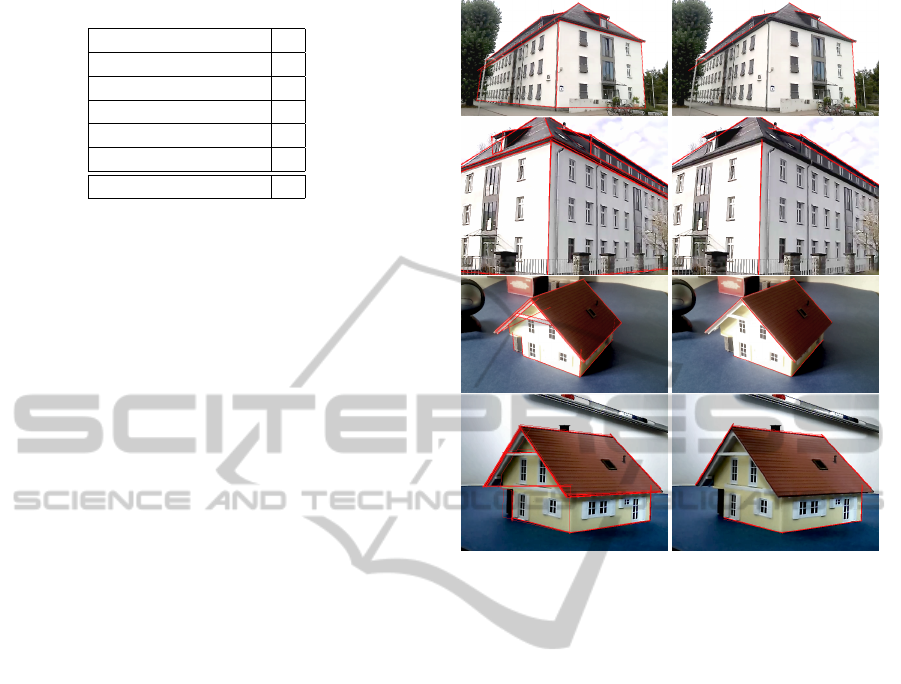
Table 1: Optimal weighting of the quality criteria.
Length 3
Distance 3
Silhouette 3
Direction 1
Light + Material 3
History 4
Matching-Feedback 2
the light quality criterion is of equal importance, but
never gains more influence than the other criteria. A
positive effect of preferring structures aligned planar
to the camera could not be verified. The history cri-
terion is strongly scene dependent. Especially when
there are few prominent large edges and a high rate
of occlusion, a higher weighting of the history entry
improves the tracking result. This is because the fea-
ture management is learning quickly about these un-
stable features and suppresses them. In a scene with
long unambiguous edges a history weight of 2 proved
sufficient for stable feature selection. As was con-
ceivable, the feedback about the matching result is the
most important criterion for a meaningful prediction
of the overall feature quality. This fact is considered
by double weighting the matching quality result on
the average of all other criteria in an additional step.
The results also show that the weighting of some qual-
ity criteria may be scene and resolution dependent.
Therefore, future research should focus on a dynam-
ical adjustment of these weights, which may be per-
formed by previous scene analysis.
Figure 8 shows the edge features in the unman-
aged approach, as well as using our feature manage-
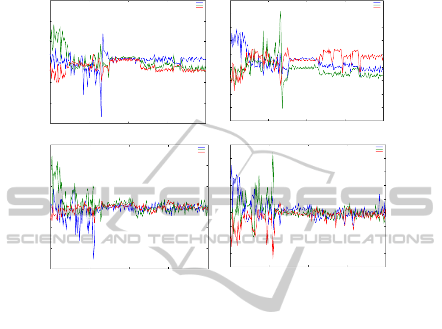
ment on four scenes. In figure 9 the translation and
rotation error are listed for one scene with and without
feature management. Comparing both approaches,
the error is smoothed by evaluating the feature quality
and leads to a more accurate pose, which shows in less
error spread concerning rotation as well as translation.
In the unmanaged approach a higher rate of jittering
occurrs and in some passes even results in corrupt or
lost camera poses due to unfiltered false correspon-
dences. Concerning computation time, in the average
over all test scenes, the feature management outper-
forms the unmanaged approach by a factor of two.
This is due to early filtering of the features, leaving
the visibility test, matcher and pose estimator with a
minimal set of features. In the best case feature eval-
uation and management could reduce the data load to
10% of 60 feature edges originally contained in the
model without losing tracking accuracy. On an HD
resolution video sequence using unmanaged tracking,
the framerate dropped below interactive rates. The
feature management approach could successfully per-
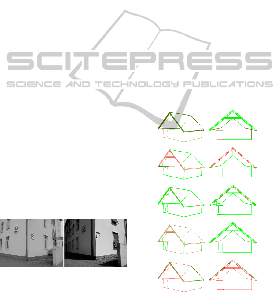
Figure 8: Edges used for tracking (red) in images from the
tracking scenes. Left: Unmanaged. Right: Feature manage-
ment.
form real-time tracking in about 10 ms per frame by
selecting the 6 best feature edges. Additionally, the
approach showed a remarkable improvement in pre-
cision on high resolution video.
4 CONCLUSIONS
The results show it is worth thinking about fea-
ture evaluation and management to improve tracking
speed and the accuracy of the estimated pose, which
is preferable especially on mobile devices. In contrast
to an unmanaged approach, evaluating the quality of
features allows for using models of arbitrary level of
detail, which may not have been created for tracking
purpose especially. Such models are often present in
industrial scenarios where applications of augmented
reality may be used for teaching, planning, assembly
and maintenance purposes. Augmented reality is also
getting popular with touristical applications. In the
near future even 3D models of whole cities and par-
ticular touristical attractive buildings will be available
(e.g. Google Earth) or can be made available easily
with small effort, which expands the possibilites for
ubiquitous urban tracking.
VISAPP2014-InternationalConferenceonComputerVisionTheoryandApplications
568
-1.5
-1
-0.5
0
0.5
1
1.5
200 250 300 350 400
Rotation error
Frames
Scene2: All-In Rotation Error
Rotation X
Rotation Y
Rotation Z
-0.04
-0.03
-0.02
-0.01
0
0.01
0.02
0.03
0.04
0.05
200 250 300 350 400
Translation error
Frames
Scene2: All-In Translation Error
Translation X
Translation Y
Translation Z
-1.5
-1
-0.5
0
0.5
1
1.5
200 250 300 350 400
Rotation error
Frames
Scene2: Feature Management Rotation Error
Rotation X
Rotation Y
Rotation Z
-0.04
-0.03
-0.02
-0.01
0
0.01
0.02
0.03
0.04
0.05
200 250 300 350 400
Translation error
Frames
Scene2: Feature Management Translation Error
Translation X
Translation Y
Translation Z
Figure 9: Pose error in one tracking scene without (top) and with feature management (bottom) for rotation (left) and transla-
tion (right). The error is shown separately for all coordinate axes.
ACKNOWLEDGEMENTS
This work was supported by grant no. MU 2783/3-1
of the German Research Foundation (DFG).
REFERENCES
Choi, C. and Christensen, H. (2010). Real-Time 3d Model-
Based Tracking using Edge and Keypoint Features for
Robotic Manipulation. In IEEE International Confer-
ence on Robotics and Automation, pages 4048–4055.
Collins, R., Liu, Y., and Leordeanu, M. (2005). On-Line
Selection of Discriminative Tracking Features. IEEE
Transaction on Pattern Analysis and Machine Intelli-
gence, 27(1):1631–1643.
Comport, A., March, E., and Chaumette, F. (2003). A Real-
Time Tracker for Markerless Augmented Reality. In
ACM/IEEE Int. Symp. on Mixed and Augmented Real-
ity, pages 36–45.
Oikawa, M., Taketomi, T., Yamamoto, G., Fujisawa, M.,
Amano, T., Miyazaki, J., and Kato, H. (2012). A
Model-Based Tracking Framework for Textureless 3D
Rigid Curved Objects. SBC Journal on 3D Interactive
Systems, 3(2):2–15.
Shi, J. and Tomasi, C. (1994). Good Features to Track.
In IEEE Computer Society Conference on Computer
Vision and Pattern Recognition, pages 593–600.
Steffens, M., Aufderheide, D., Kieneke, S., Krybus, W.,
Kohring, C., and Morton, D. (2009). Probabilistic
Scene Analysis for Robust Stereo Correspondence. In
Proceedings of the 6th International Conference on
Image Analysis and Recognition, pages 697–706.
Vacchetti, L., Lepetit, V., and Fua, P. (2004). Combining
Edge and Texture Information for Real-Time Accurate
3D Camera Tracking. In ACM/IEEE Int. Symp. on
Mixed and Augmented Reality, pages 48–57.
Wuest, H., Pagani, A., and Stricker, D. (2007). Feature
Management for Efficient Camera Tracking. In Com-
puter Vision ACCV 2007, volume 4843 of Lecture
Notes in Computer Science, pages 769–778.
Wuest, H. and Stricker, D. (2007). Tracking of Industrial
Objects by Using CAD Models. Journal of Virtual
Reality and Broadcasting, 4(1).
FeatureEvaluationandManagementforCameraPoseTrackingon3DModels
569
