RF FRONT-END CONSIDERATIONS FOR FUTURE MULTI-
BAND MOBILE TERMINALS
Hiroshi Okazaki, Takayuki Furuta, Kunihiro Kawai, Yuta Takagi and Shoichi Narahashi
Research Laboratories, NTT DOCOMO, INC., 3-6, Hikarinooka, Yokosuka, JAPAN
{okazakih, furutat, kawaikun, takagiyu, narahashi}@nttdocomo.co.jp
Keywords: Low noise amplifier, Multi-mode multi-band terminal, Multi-band power amplifier, RF filter, RF front-end.
Abstract: A Radio Frequency (RF) front-end (RF-FE) is one of the keys in multi-mode and multi-band mode mobile
terminals. In conventional cellular phones, multiple RF-FEs are installed for multi-band use. There have
been a lot of studies of achieving multi-band or broadband circuits that comprise a compact and cost-
effective multi-band RF-FE with adequate RF performance. Reconfigurable or tunable RF-FEs are a way to
provide multi-band function in future mobile terminals, which takes into consideration the capability to
support a large number of wireless systems that use different frequency bands. However, the performance
degradation should be considered if adaptive circuits are installed in the RF-FE. This paper presents
considerations for the issues that might occur in a multi-band RF-FE for future mobile terminals. As an
example, a concept of collaboration between a top RF filter and low-noise amplifier (LNA) is presented.
1 INTRODUCTION
After explosive growth of smart-phones, connecting
to the Internet and/or someone else anywhere
anytime is becoming necessary in modern lifestyle.
To be able to connect from anywhere with adequate
bit rate, mobile terminals must have multi-mode and
multi-band operation capabilities. In other words,
mobile terminals will be expected to function in all
the required wireless systems and frequency bands.
With regard to frequency bands for cellular systems,
some reports indicate that the number of frequency
bands required for a global mobile terminal is 3-5
for the third generation (3G) cellular system and it
will be increased to 7-9 in the Long Term Evolution
(LTE) era. A Radio frequency (RF) front-end (RF-
FE) is one of the key components for the global
mobile terminal, which should cover a vast number
of frequency bands. In this paper, the RF-FE
consists of power amplifier(s) (PA(s)), RF filters as
a part of duplexers, antenna switches and low noise
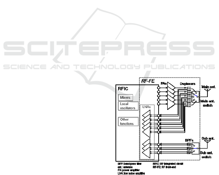
amplifier(s) (LNA(s)). In conventional cellular
phones, multiple PAs, filters, and LNAs are installed
for multi-band use, as shown in Figure 1. RFIC
generally includes most of RF functions except PA,
duplexer, band-pass filter (BPF) and antenna switch,
and may have transceivers for wireless local area
network (WLAN), Bluetooth and a receiver for the
Global Positioning System (GPS).
Figure 1: A conventional RF-FE configuration for
frequency-division duplexing (FDD) systems.
58
Okazaki H., Furuta T., Kawai K., Takagi Y. and Narahashi S.
RF FRONT-END CONSIDERATIONS FOR FUTURE MULTIBAND MOBILE TERMINALS.
DOI: 10.5220/0004785300580061
In Proceedings of the Second International Conference on Telecommunications and Remote Sensing (ICTRS 2013), pages 58-61
ISBN: 978-989-8565-57-0
Copyright
c
2013 by SCITEPRESS – Science and Technology Publications, Lda. All rights reserved
The RF-FE configuration shown in Figure 1 is
based on a conventional scheme, which is selecting
the most suitable circuit combination from among
several built-in circuits for each frequency band. The
RF-FE in the figure can process 5 different
frequency bands, and also have a diversity or 2-
stream multiple-input and multiple-output (MIMO)
receiving capability at 3 out of the 5 bands by using
a sub receiver. However, the conventional
configuration will reach impasse, and the terminal
employing the configuration will be bulky and
expensive. This is because the terminal handling m
bands and n spatial streams for MIMO should have
(m x n) transceivers in it. Therefore, there have been
a lot of studies of achieving multi-band or
broadband circuits that comprise a compact and
cost-effective multi-band RF-FE with adequate RF
performance (Hueber and Staszewski (Ed.), 2011),
(Bezooijen, Mahmouji, and Roermund, 2011). A
reconfigurable or tunable technique seems to be a
way to provide a multi-band RF-FE that supports a
large number of frequency bands. An example is
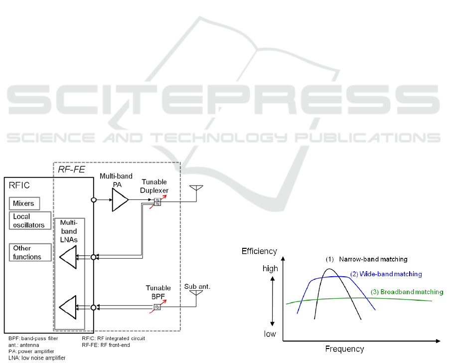
shown in Figure 2. However, the performance
degradation should be considered if adaptive circuits
are installed in the RF-FE. This paper presents
considerations for the issues that might occur in a
multi-band RF-FE for future mobile terminals. As an
example, a concept of collaboration between a top
RF BPF and LNA is presented.
Figure 2: An example of RF-FE configuration employing
multi-band circuits for FDD systems.
2 CONSIDERATIONS ON MULTI-
BAND CIRCUITS
In this section, some considerations on each
component in RF-FE are presented.
2.1 PA
In conventional configuration shown in Figure 1,
highly sophisticated PAs are employed. Each of
those PA is optimized for a specific frequency band
and modulation scheme (mode) operation, thus, it is
called as a single-band PA. The main concern of the
PA for the mobile terminal is efficiency at required
output power levels and spurious specifications at an
operating frequency. Generally, efficiency versus
frequency characteristics show a peak. That means
frequency range where the PA works at high
efficiency is limited. There are trade-off relationship
between efficiency and frequency range. Figure 3
shows a rough comparison of the efficiency
characteristics with PA design schemes.
A single-band PA is usually designed by a
narrow-band matching scheme. A multi-band PA
based on wide-band matching (wide-band PA) can
cover closely-located frequency bands, such as 800,
850 and 900 MHz bands, in compensation for some
efficiency degradation from the single-band PA. A
wide-band PA is becoming popular because it can
merge several PAs which should be required for the
conventional RF-FE in a multi-band terminal.
However, the wide-band PA is not practical to
merge the PAs for widely spread frequency bands,
such as 800 and 1900 MHz bands. The PAs based on
broadband or distributed matching generally achieve
lower efficiency than the wide-band PA, and they
are not suitable to use in the mobile terminal.
Figure 3: A comparison of design schemes of PA on
efficiency versus frequency characteristics.
RF Front-End Considerations for Future Multiband Mobile Terminals
59

Figure 4: Circuit diagram of reconfigurable amplifier with
switches in its matching networks.
On the other hand, a PA with reconfigurable or
tunable matching network is expected to achieve
high efficiency at each frequency band even if the
bands are widely spread. The PAs have variable
devices such as switches or varactors in their
matching networks to change their operating
frequency. Figure 4 shows a circuit diagram
example of a reconfigurable amplifier. The status or
parameters of the variable devices are set to
optimized values for high efficiency based on
narrow-band matching at each target frequency.
However, efficiency degradation should be
considered because the variable components have
losses. In the case of the reconfigurable PA with
switches, detailed evaluations were presented and it
is reported that the degradation can be mitigated
(Fukuda, et al., 2011).
2.2 Filters and LNAs
Figure 5 shows an example of a receiver RF-FE
configuration, which is one generation earlier than
that shown in Figure 1. With the progress of CMOS
process and efforts on circuit technologies such as
“SAW-less” technique (Darabi, 2007), it becomes
natural that the LNA is integrated into an RFIC, and
the BPF between LNA and RFIC shown in Figure 5
is removed. The main concerns of a LNA for the
mobile terminal are sensitivity (gain and noise
figure) and linearity, which includes immunity from
out-of-band signals. Broadband or wide-band
operation of the LNA itself seems to be easier than
that of an efficient PA.
Figure 5: One generation earlier receiver RF-FE
configuration example of receiver side.
Figure 6: Inter-band CA.
Comparing the receiver configurations shown in
Figures 1 and 2, only tunable BPF is required to
configure the RF-FE shown in Figure 2. However, it
is a considerable challenge to attain a tunable BPF
with low-loss at pass-band, high isolation at
suppression band, and a wide-tuning frequency
range.
Carrier aggregation (CA) technology that
employs several bands aggregately and concurrently
will be utilized to obtain a wide operating band-
width in the LTE-advanced era. Figure 6 shows an
example of spectrum usage in inter-band CA. One
technical issue for the CA is configuring a duplexer
and BPF. Characteristics at the combination band
should be considered in the duplexer design in
addition to a conventional duplexer design scheme
which mainly considers characteristics at an original
frequency band for isolation between transmitter and
receiver. Because so many combinations of pair-
bands are considered for the inter-band CA, a
conventional duplexer-bank scheme will make a
global terminal more bulky, and using tunable BPFs
and tunable band-elimination filers (BEFs) will
become more valuable. Otherwise localized mobile
terminals for a specific carrier, county, or region will
revest.
Considering a tunable filter as a part of the
tunable duplexer, one of the serious problems for
receiver chain is to generate gain and phase
modulation caused by strong out-of-band signals.
The LNA will be required to enhance its frequency
selectivity in order to prevent the performance
degradation from undesired out-of-band signals in a
multi-band receiver that yields non-optimum RF
filter performance. Frequency response adjustment
of the LNA will be a solution.
Figure 7 shows small signal frequency responses
of the reconfigurable LNA that has a same circuit
topology shown in Figure 4. The responses were
obtained in two different switch states (0 and 1) at a
class A bias condition. Figure 8 shows the results of
the gain suppression measurement at 3.1 GHz with
out-of-band signals of 2 GHz. From the results
above, the input power of 3.1 GHz for each state is
set to -20.3 dBm, which lies in a linear region. In the
figure, “gain difference” and “gain diff. at 3.1-GHz,”
correspond to the difference in gain at 3.1 GHz
Second International Conference on Telecommunications and Remote Sensing
60
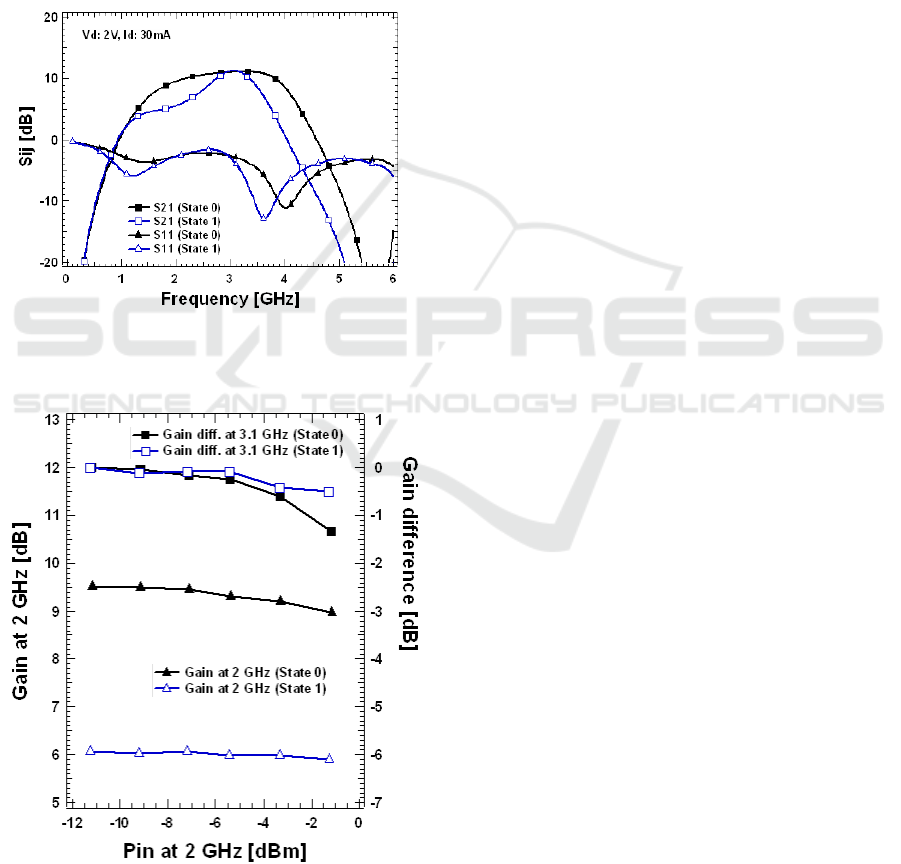
between with and without the 2.0-GHz signal input
power indicated on the horizontal axis, respectively.
The gain of the 2.0-GHz signal without the 3.1-GHz
input is also shown for comparison. The gain
suppression is observed at a higher level of 2.0-GHz
input power, and is mitigated in state 1. Thus, the
frequency response adjustment of the LNA is
effective in the gain suppression problem caused by
out-of-band signals as well as filter response
improvement. (Okazaki, et al., 2010)
Figure 7: Frequency response of reconfigurable LNA.
Figure 8: Results of the gain suppression measurement.
3 CONSIDERATIONS ON
OVERALL RF-FE
One of the main issues for the overall RF-FE is
known collectively as RF coexistence, which is a hot
topic (Sahota, 2012). A modern mobile phone has
different kind of RF systems such as cellular,
WLAN, Bluetooth, GPS, etc., which will be
activated at the same time. Each of them may
become a source of interference and also a victim of
that. Moreover, the MIMO and intra-band CA
require also simultaneous operation within multiple
transceivers for cellular systems. It seems to be
difficult to work all the RF transceivers and
receivers installed in a multi-band mobile terminal
with expected performance in RF quiet environment.
4 CONCLUSIONS
Several RF-FE considerations for future multi-band
mobile terminals are described. Some of them will
be solved but others such as ideally tunable filters
are remained as issues to be solved and the problems
of RF coexistence are still growing. Continuous
efforts and innovations are really needed.
REFERENCES
Bezooijen, A., Mahmouji, R., Roermund, A., 2011.
Adaptive RF Front-Ends for Hand-held Applications,
Springer. Dordrecht/Heidelberg/London/New York.
Hueber, G., Staszewski, R.B., (Ed.), 2011. Multi-
Mode/Multi-Band RF Transceivers for Wireless
Communications: Advanced Techniques, Architectures,
and Trends, John Wiley & Sons, Inc. Hoboken, New
Jersey.
Fukuda, A., Furuta, T., Okazaki, H., Narahashi, S., Nojima,
T., 2012. Low-Loss Matching Network Design for
Band-Switchable Multi-Band Power Amplifier. IEICE
Transactions on Electronics E95-C: 1172-1181.
Darabi, H., 2007. A Blocker Filtering Technique for
SAW-Less Wireless Receivers. IEEE Journal of Solid-
State Circuits, 42: 2766-2773.
Okazaki, H., Fukuda, A., Kawai, K., Furuta, T.,
Narahashi, S., 2010. Reconfigurable amplifier towards
enhanced selectivity of future multi-band mobile
terminals. In International Microwave Workshop
Series on RF Front-ends for Software Defined and
Cognitive Radio Solutions, IEEE.
Sahota, K., 2012. Coexistence Issues and Mitigation in
Multi-Mode Band Cellular Radios, In International
Microwave Symposium, Workshop WSG, IEEE.
RF Front-End Considerations for Future Multiband Mobile Terminals
61
