
SAO Filtering inside CTU Loop for High Efficiency Video Coding
Adireddy Ramakrishna, N. S. Prashanth and G. B. Praveen
PathPartner Technology Consulting Pvt Ltd, New Thippasandra Main Raod, Bangalore, India
Keywords: HEVC, in-Loop Filter, De-blocking Filter, Sample Adaptive Offset (SAO) Filter, Coding Tree Unit (CTU).
Abstract: In the HEVC standardization process, the In-loop filter module is added with a new video coding tool called
sample adaptive offset (SAO). SAO is placed after de-blocking in video coding loop. The HM
implementation (HM10.0, 2013) & the standard (Bross et al., 2013) indicates picture basis in-loop filtering
i.e., both de-blocking and SAO. Although standard specifies picture basis de-blocking operation, it added a
note indicating the possibility of CTU/CU level de-blocking execution. But there is no such mention of
possibility for SAO execution at CTU/CU level. Standard explains about applying SAO filter on entire
picture after reconstruction and de-blocking. But many-a-time, for the purpose of low-latency, better
memory-bandwidth efficiency and cache performance, it is needed to implement SAO filter at CTU level
for majority applications. As well, if any Hardware Accelerator (HWA)/ASIC to be developed for HEVC,
all modules are very much expected to execute at CTU/CU level for better pipeline performance. This paper
presents & discusses the possibility of bringing SAO at CTU level after de-blocking.
1 INTRODUCTION
In-loop filtering employed by video coding
standards, such as H.264/AVC & H263 Annex-J, to
improve the video quality by removing blocking
artifacts. In HEVC, two in-loop filtering stages are
opted. The first stage is de-blocking filter and next
stage is Sample Adaptive Offset (SAO) filter. One or
two of these filtering stages can be optionally
applied before storing the reconstructed picture into
the decoded picture buffer (DPB). The De-Blocking
Filter (DBF) is used similar to the one in
H264/AVC, but the DBF has been simplified with
regard to its decision making and filtering process.
SAO is a non-linear amplitude mapping filter which
operates on DBF data. The goal of SAO is to
improve the reconstruction of the signal amplitudes
by a lookup table mapping. HEVC specifies that two
types, Band Offset (BO) or Edge Offset (EO), of
SAO operations can be selected for each CTU. Both
the SAO types add a certain offset value to the
sample, the offset gets chosen from the lookup table
based on the local gradient at that sample position.
HEVC Final Draft International Standard (FDIS)
explains SAO process to happen on complete picture
due to its dependencies on neighbours. But
executing SAO process inside CTU loop is
advantageous due to below mentioned reasons.
Firstly, if SAO is applied on the CTU immediately
after reconstruction and de-blocking, the pixel data
for current CTU is readily available in local memory
(cache) which will avoid data access/copy from
main memory separately for SAO. This improves
the performance due to better cache performance
and reduced memory band-width. The second reason
is, if SAO is applied after entire image
reconstruction, then outputting the data to
application need to wait until reconstruction and de-
blocking of entire image is completed before starting
SAO process. This will be a major issue in low-
latency applications.
For SAO to be applied on any CTU, it requires
de-blocked pixels from all of its eight neighbours
(Left, Top Left, Top, Top Right, Right, Bottom
Right and Bottom). This neighbour data is
particularly needed only when SAO type is of edge
offset. Hence there is a challenge to move SAO
inside CTU loop as not all the neighbours are
available at the time of encoding or decoding at
CTU level.
In this paper, we detail an approach on similar
lines of de-blocking execution at CTU level. Unlike
de-blocking operation, SAO has more number of
neighbour dependencies. The proposed approach
discusses the additional complexities, local/internal
memory requirements and handling to accomplish
the SAO operation inside CTU loop. This paper is
19
Ramakrishna A., Prashanth N. and Praveen G..
SAO Filtering inside CTU Loop for High Efficiency Video Coding.
DOI: 10.5220/0004613200190022
In Proceedings of the 10th International Conference on Signal Processing and Multimedia Applications and 10th International Conference on Wireless
Information Networks and Systems (SIGMAP-2013), pages 19-22
ISBN: 978-989-8565-74-7
Copyright
c
2013 SCITEPRESS (Science and Technology Publications, Lda.)

organized as follows. Section 2 provides an
overview of SAO operation and Sections 3 & 4
describe the proposed method. Finally, conclusions
and future work are given in section 5.
2 OVERVIEW
High efficiency Video Coding (HEVC) also known
as H265 video codec is the latest video compression
standard developed by Joint Collaborative Team on
Video Coding (JCT-VC) group which was
established by the ISO/IEC Moving Picture Experts
Group (MPEG) and ITU-T Video Coding Experts
Group (VCEG). HEVC is expected to achieve up to
50% better compression when compared to the
Advanced Video Coding (AVC/H.264) standard,
while maintaining similar video quality levels
(Sullivan et al., 2012). In HEVC, pictures are
uniformly divided into square blocks called Coding
Tree Units (CTU) which is similar to Macro blocks
used in earlier standards. These CTUs are further
divided in quad-tree basis to form Coding Units
(CU) which forms the basic processing unit (Bross
et al., 2013).
SAO is an in loop filter used in HEVC standard
to improve the objective quality of the reconstructed
pictures. SAO filtering is a non-linear operation
which further reduces the reconstruction error which
are not achieved by many of the linear filters and
particularly used to enhance the edge sharpness. It is
found that, SAO is efficient in suppressing banding
artifacts (pseudo edges) and ringing artifacts caused
by quantization errors of high frequency components
in transform domain (Sullivan et al., 2012).
SAO is applied post de-blocking process. Since
the characteristics of a picture may vary with
locations, SAO divides a picture into CTU-aligned
regions to obtain local statistical information (Fu,
Chen et al., 2011). Each CTU will contain its own
SAO parameters. SAO class for a CTU can be
invalid (meaning SAO is not applied on current
CTU), Band Offset (BO) or Edge Offset (EO).
In case of BO, pixel intensities are divided into
32 fixed bands as show in Fig 1. For 8 bit samples,
width of the band will be 8 samples. Offsets are sent
for four consecutive bands from given band position,
which are prominent in the current CTU (Fu, Chen
et al., 2011). Four consecutive bands are used since
flat areas with banding artifacts, with most sample
intensity concentrated in only few bands. Offsets are
nothing but the averaged difference between original
samples and de-blocked samples. These offsets are
added to all pixels which fall in that particular band.
SAO offsets are limited between -7 to 7. In case of
band offset, sign of each offset is sent in bit-stream
separately (Sullivan et al., 2012).
Figure 1: SAO Bands in Band Offset type.
EO class uses neighbor pixels to compute index
of the offset array. Based on neighbors being used,
EO class is further divided into four types (a) EO-0
(0 degree), (b) EO-1(90 degree), (c) EO-2(135
degree), (b) EO-3(45 degree) as show in Fig 2. 0
degree uses left and right pixels, 90 degree uses top
and bottom pixels, 135 degree uses top left and
bottom right pixels and 45 degree uses top right and
bottom left pixels. In all SAO edge offsets types,
each pixel inside the CTB is classified into one of 5
categories i.e., Local minima, positive edge, flat
area, negative edge and local maxima which are
explained in Table 1. Each category will have its
corresponding edge offset. In case of edge offset, in
order to reduce bit overhead, SAO specifies positive
offset for local minimum & negative edge, and
negative offset for local maximum & positive edge
(Sullivan et al., 2012).
Figure 2: SAO Edge Offset types.
Table 1: SAO Edge Offset categories.
Category Condition
Local minima Current pixel less than both neighbors
positive edge
Current pixel greater than one neighbor
and equal to the other
flat area Current pixel is equal to both neighbors
negative edge
Current pixel less than one neighbor and
equal to the other
local maxima Current pixel greater than both neighbors
SIGMAP2013-InternationalConferenceonSignalProcessingandMultimediaApplications
20
Standard explains SAO process in picture basis
but implementation of SAO in CTU loop is possible
and is explained in next two sections.
3 DECODER PERSPECTIVE
After reconstructing a CTU, it is not possible to de-
block the entire CTU as Right and Bottom CTUs are
unavailable. According to the standard (Bross et al.,
2013), at CTU edge, maximum of three pixel lines
can get affected due to de-blocking. Thus after de-
blocking of the reconstructed CTU, completely de-
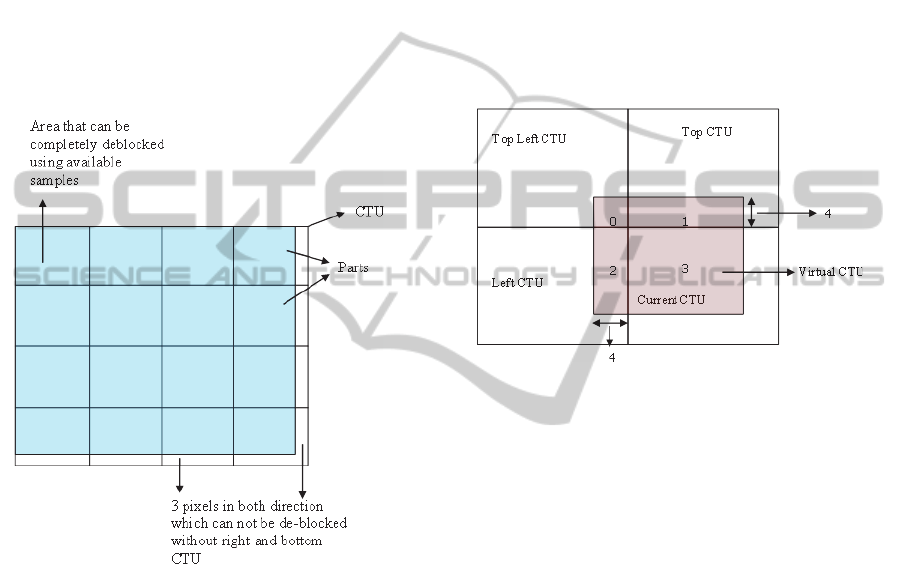
blocked samples of the CTU are as shown in Fig 3.
Figure 3: De-blocked pixels in a CTU.
As shown in Fig 3, only three right most pixel
columns and three bottom most pixel rows are
partially/not filtered by de-block operation. Since
SAO process always uses de-blocked samples as its
input (Bross et al., 2013), these pixel data should not
be used for SAO processing at this moment. Along
with this right and bottom most 3-pixel lines, we
need to leave one more extra pixel line as SAO-EO
class demands one neighbour pixel line. Hence, four
right most columns and four bottom most rows can
not become part of the SAO process for current
CTU.
In order to accomplish de-block filtering
operation at CTU loop as mentioned in standard
(Bross et al., 2013), Right column and Bottom row
buffers with 3-pixel line size needs to be maintained
for partially/not de-block filtered pixels. By adding
one extra pixel line to above mentioned buffers, it is
possible to maintain the pixels that are not SAO
processed. Left column and Top row de-blocked
samples for the current CTU can be maintained
using internal line buffers before SAO gets
processed on corresponding CTUs.
The pixels which are not SAO processed in
current CTU become part of next CTUs in raster
scan order and form a virtual CTU as shown in
Fig.4. This virtual CTU size is same as actual CTU
size and comprises of current and 3-neighbor CTU
blocks with all required neighbour dependencies
cleared. Hence the effective SAO processing inside
CTU loop happens on size of one complete CTU.
Figure 4: Virtual CTU for SAO process.
These four partial CTUs of virtual CTU needs to
be processed using different SAO parameters (SAO
type and offsets) as each one belong to different
CTU. As SAO parameter data is very minimal, it can
be maintained in internal memory. Even if it has to
be fetched from external memory, the memory band-
width would be insignificant. Approach explained
here can be used in encoder’s reconstruction path.
4 ENCODER PERSPECTIVE
In encoder, SAO process can be divided into two
stages. First stage is where SAO type and offsets are
estimated and second stage is the filtering operation.
First stage can be further classified into statistics
collection; best offset estimation, SAO type
selection and merge decision. Statistics are collected
for every sample of the CTU for each SAO type.
Based on the collected statistics, best offsets are
estimated for all SAO types. Cost is estimated for
each SAO type after offset estimation, based on
which best SAO type is selected.
Complete SAO process can be moved inside
CTU encoding loop with insignificant trade-off in
quality. SAO estimation is performed on entire CTU
SAOFilteringinsideCTULoopforHighEfficiencyVideoCoding
21

where three Right most columns of samples and
three Bottom most rows of samples are partially/not
de-blocked as shown in Fig 5. In case of 64x64
CTU, only 9.155% of current CTU pixels that are
partially/not de-blocked involve in SAO offset
estimation and SAO type selection. Similarly, in
case of 32x32 CTU these are of 17.87%. As the
percentage of non de-blocked samples in the CTU is
very less, penalty for using these samples in SAO
estimation is expected to be very minimal.
Figure 5: Samples for SAO estimation.
After SAO estimation is complete, filtering
operation for the CTU is performed similar to the
method explained in the earlier section for decoder.
5 CONCLUSIONS
Though HEVC standard explains about applying
SAO filter after de-blocking of entire image as
implemented in HM reference software (HM10.0,
2013), it is possible to move SAO process inside
CTU decoding/encoding loop with some
compromises in encoder SAO estimation and with
some complexities in reconstruction path which will
improve overall system performance and memory
bandwidth. The proposed approach is in the process
of implementation and current observation indicates
it to be a feasible solution. Our future work will
include the computational complexity and
implementation details for both encoder & decoder.
Future works for hardware realization of HEVC can
consider the proposed ideas.
REFERENCES
B. Bross, W.-J. Han, G. J. Sullivan and T. Wiegand, 2013.
High Efficiency Video Coding (HEVC) text
specification draft 10 (FDIS). In JCT-VC 12
th
meeting,
Geneva, CH.
G. J. Sullivan, J.-R. Ohm, W.-J. Han and T. Wiegand,
2012. Overview of the High Efficiency Video Coding
(HEVC) Standard. In IEEE Trans. on Circuits and
Systems For Video Technology, vol.22, pp.1649-1668,
Dec, 2012.
C.-M. Fu, C.-Y. Chen, Y.-W. Huang and S. Lei, 2011.
Sample Adaptive Offset for HEVC. In MMSP’11,
IEEE 13
th
International workshop on Multi-Media
Signal Processing.
HEVC Test Model Ref. software 10.0 (HM10.0), 2013.
Available:https://hevc.hhi.fraunhofer.de/svn/svn_HEV
CSoftware/tags/HM-10.0/.
SIGMAP2013-InternationalConferenceonSignalProcessingandMultimediaApplications
22
