
Distributed Localization and Scene Reconstruction from RGB-D Data
Sergio Ayuso
1
, Carlos Sag
¨
u
´
es
1
and Rosario Arag
¨
u
´
es
2,3
1
Instituto de Investigaci
´
on en Ingenier
´
ıa de Arag
´
on, Universidad de Zaragoza,
Mar
´
ıa de Luna 1 E-50018, Zaragoza, Spain
2
Clermont Universite, Institut Pascal, BP 10448, F-63000, Clermont-Ferrand, France
3
CNRS, UMR 6602, IP, F-63171, Aubiere, France
Keywords:
Network Robots, RGB-D Sensing, Distributed Systems, 3D Mapping and Localization.
Abstract:
In this paper we present a method to make every robot of a team to compute a global 3D map of the scenarios
explored by all the members, obtaining also the trajectories of the team. Every robot has a RGB-D device on
board which gives RGB and depth data simultaneously and uses this information to build its own local map
in real time. Once all robots have formed their local maps, they start a communication process to transform
all maps to a common reference and merge them. The interest of this work is related to the establishment of
the global reference and the management of the local point clouds to get correspondences between local maps
which make possible to obtain the best possible transformation from the reference of every robot to the global
reference.
1 INTRODUCTION
The increasing interest in multi-robot applications is
motivated by the wealth of possibilities offered by
teams of robots cooperatively performing collective
tasks. The efficiency and robustness of these teams
goes beyond what individual robots can do. In these
scenarios, distributed strategies attract a high atten-
tion, especially in applications which are inherently
distributed in space, time or functionality. These dis-
tributed schemas do not only reduce the completion
time of the task due to the parallel operation, but also
present a natural robustness to failures due to the re-
dundancy. Our research is focused on distributed ap-
plications for perception tasks. Perception is of high
importance in robotics, since almost all robotic appli-
cations require the robot team to interact with the en-
vironment. Then, if a robot is not able to obtain an en-
vironmental representation from others, or an a priori
representation is not available, it must posses percep-
tion capabilities to sense its surroundings. Perception
has been long studied for single robot systems and a
lot of research has been carried out in the fields of lo-
calization, map building and exploration. Among the
different sensors that can be used to perceive the en-
vironment, we are interested in visual perception, and
the multiple benefits of using cameras have motivated
the interest of many researchers. These benefits in-
clude the property that cameras are able to sense quite
distant features so that the sensing is not restricted to a
limited range. An additional kind of cameras of high
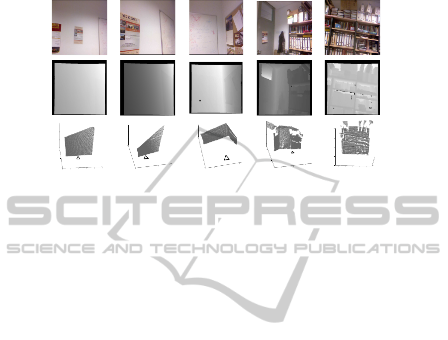
interest are RGB-D devices (Fig. 1). They provide
both regular RGB (Fig. 2, first row) and depth image
information (Fig. 2, second row). Thus, it is possible
to compute the landmark 3D position from a single
image (Fig. 2, third row).
Figure 1: Example of a RGB-D camera.
A general overview of the achieved results, and the
current and future research lines in distributed multi-
robot systems can be found in (Parker, 2000). Many
existent solutions for single robot perception have
been extended to multi-robot scenarios under cen-
tralized schemes, full communication between the
robots, or broadcasting methods. In (Fox et al., 2006)
maps are represented as constraint graphs, where
nodes are scans measured from a robot pose and edges
represent the difference between pairs of robot poses.
Robot to robot measurements are used to merge two
local maps into a single map.
Distributed estimation methods (Olfati-Saber,
2007) maintain a joint estimate of a system that
evolves with time by combining noisy observations
taken by the sensor network. Early approaches sum
377
Ayuso S., Sagüés C. and Aragüés R..
Distributed Localization and Scene Reconstruction from RGB-D Data.
DOI: 10.5220/0004485103770384
In Proceedings of the 10th International Conference on Informatics in Control, Automation and Robotics (ICINCO-2013), pages 377-384
ISBN: 978-989-8565-71-6
Copyright
c
2013 SCITEPRESS (Science and Technology Publications, Lda.)
−1000
−500
0
500
1000
1500
0
1000
2000
−500
0
500
1000
x
z
y
−500
0
500
1000
0
1000
2000
0
500
1000
x
z
y
−500
0
500
0
500
1000
1500
2000
−1000
0
1000
x
z
y
−1000
0
1000
0
1000
2000
3000
−1000
0
1000
x
z
y
−1000
−500 0
500
1000
0
1000
2000
−1000
−500
0
500
1000
z
x
y
Figure 2: An example of the images obtained with the RGB-D sensor.
the measurements from the different agents in IF (In-
formation Filter) form. If the network is complete,
then the resulting estimator is equivalent to the cen-
tralized one. In general networks the problems of
cyclic updates or double counting information ap-
pear when nodes sum the same piece of data more
than once. Other approaches (Alriksson and Rantzer,
2006) use distributed consensus filters to average the
measurements taken by the nodes. A related scenario
with estimation is sensor fusion (Lynch et al., 2008;
Calafiore and Abrate, 2009), where measurements ac-
quired by several sensors are fused in a distributed
fashion. Distributed perception methods must address
specific challenges such as associating the elements
observed by the robots in a globally consistent way,
or computing the relative poses of the robots and es-
tablishing a common reference frame for the whole
robot team.
The data association problem consists of estab-
lishing correspondences between different measure-
ments or estimates of a common element. Traditional
data association methods, like the Nearest Neigh-
bor and Maximum Likelihood (Kaess and Dellaert,
2009), the Joint Compatibility Branch and Bound
(JCBB) (Neira and Tard
´
os, 2001), or the Combined
Constraint Data Association (Bailey et al., 2000) are
designed for single robot systems. Multi-robot ap-
proaches have not fully addressed the problem of data
association. Many methods rely on broadcasting con-
trols and observations or submaps, see e.g., (Gil et al.,
2009), and solve the data association using a cycle-
free order, thus essentially reducing the problem to
that of the single robot scenario.
The problem of estimating the common reference
frame for the team of robots is motivated by the fact
that, in general, the robots start at unknown locations
and do not know their relative poses. This informa-
tion can be recovered by comparing their local maps
and looking for overlapping regions. This approach,
known as map alignment, has been deeply investi-
gated and interesting solutions have been presented
for feature-based (Thrun and Liu, 2003) and occu-
pancy grid (Carpin, 2008) maps. However, it has
the inconvenience that its results depend on the accu-
mulated uncertainty in the local maps. Alternatively,
the relative poses between the robots can be explicitly
measured (Sagues et al., 2006).
In this work we propose a distributed solution to
compute the 3D global map. Each robot obtains ro-
bust matches based on descriptors of the features in
successive images, and it builds its 3D local map
based on this information. As it may happen that the
neighbor robots in communication have not common
3D maps, we search for robots in the network which
have observed common regions of the 3D scene. Fi-
nally, all our robots obtain the same global map,
which is composed of both individual and common
regions. The robot with the most common parts with
other robots is also selected as the reference robot.
2 ROBOT NETWORK
The multi-robot system is composed by N robots,
each one with one RGB-D sensor to acquire the infor-
mation from the scene. Additionally they can commu-
nicate with the other members of the team. The robots
are labeled by i ∈ V = {1, . . . , N} and each robot in
the team i ∈ V can be univocally identified, for ex-
ample, considering the IP addresses the robots use to
communicate.
ICINCO2013-10thInternationalConferenceonInformaticsinControl,AutomationandRobotics
378

Figure 3: Two graphs with six robots. On the left is a com-
plete communication graph and on the right an incomplete
communication graph.
We assume that the limited communication capabil-
ities imply that not all the robots will be able to
directly exchange information with each other (Fig-
ure 3). These limitations can be modeled using a
graph G = {V , E}, where E ⊂ V × V contains the
pairs of robots that can directly communicate. We
say that there is a communication link between i and
j when they can directly exchange messages, which
happens if and only if (i, j) ∈ E. And we define the
neighbors of a robot i ∈ V as the set of robots that can
directly communicate with i,
N
i
= { j ∈ V | (i, j) ∈ E}. (1)
We will consider undirected communications. That
is, (i, j) ∈ E ⇔ ( j, i) ∈ E and j ∈ N
i
⇔ i ∈ N
j
. In
this paper, we assume that the graph G is fixed over
the time.
We formally define the consensus problem and
present solutions to solve it using a distributed lin-
ear iteration. The consensus problem is formally de-
fined as follows: Given initial conditions x
i
(0), i =
1, . . . , N, we define the consensus problem as the
problem of making the state of all the robots regard-
ing the quantity of interest reach the same value, com-
puted as a function, f , of the initial observations:
x
i
= x
j
= f (x
k
(0)), k = 1, . . . , N, for all i and j in V .
This problem has a great importance in many robotic
tasks such as sensor fusion and formation control. In
the first case it is required for a proper representation
of the environment whereas in the second is relevant
to achieve a desired configuration, e.g., to make all the
robots meet at a fixed point or explore a some region.
The solutions we are interested in correspond with
distributed algorithms that follow a linear iteration
scheme. Linear iterations are very easy to implement,
as they only require to compute linear combinations
of different quantities. This simplicity makes them
very interesting to be used in a distributed setup. In
addition, they represent an important class of iterative
algorithms that find applications in optimization or in
distributed decision making (Bullo et al., 2009). A
linear iteration computes weighted sums of the differ-
ent values to achieve this objective. Specifically, each
robot updates its value of the quantity of interest com-
puting a weighted sum of its previous value and that
of its direct neighbors,
x
i
(t + 1) = w
ii
(t)x
i
(t) +
∑
j∈N
i
(t)
w
i j
(t)x
j
(t). (2)
In the previous equation w
i j
is the Metropolis weight
associated to the information given by the neighbor
j (Xiao et al., 2005). We refer to iteration (2) as
the standard discrete time distributed consensus algo-
rithm. The extension to quantities of the dimension
of the RGB-D data acquired by the robot is straight-
forward, applying the same iteration rule for each one
of the scalar components of the state vector indepen-
dently.
If we consider the update rule of all the robots
simultaneously, we can model the update as a N-
dimensional discrete-time linear dynamical system
with dynamics inherently related to the network struc-
ture,
x(t + 1) = W(t)x(t), (3)
with x(t) = (x
1
(t), . . . , x
N
(t))
T
the values of the data
acquired by the robots in vectorial form and W(t) =
[w
i j
(t)] ∈ R
N×N
, the weight matrix generated using
all the individual weights.
In case of using a distributed linear iteration like
(2) then the algorithm is fully distributed because each
robot is only using the information provided by its
neighbors in the communication graph, and the robots
do not need to know the topology of the whole net-
work to execute these algorithms, they only require
the information about their direct neighbors.
On the other hand, the use of this kind of iter-
ations assume that the communications between the
robots are synchronous and uncorrupted. Neverthe-
less, some of the most standard issues in communi-
cation can be handled by a proper modeling of the
communication graph. For example, packet drops
and communication failures can be seen as regular
changes in the communication topology and asyn-
chronous communications can be modeled by consid-
ering a directed communication graph. Therefore, if
we design our algorithms in such a way that they can
handle these topologies, we can expect them to be ro-
bust to these communication issues.
One interesting point is to assign the appropriate
weights to the different elements so that different con-
sensus objectives are achieved. In the case of averag-
ing, we suppose that all the observations of all the
robots have the same importance because the average
weights all of them equally,
¯x =
1
N
∑
i∈V
x
i
(0). (4)
DistributedLocalizationandSceneReconstructionfromRGB-DData
379

The average of the initial information of the robots
can be achieved very easily using a linear iteration.
We consider that the communication graph remains
fixed during the execution of the whole iteration, i.e.,
W(t) = W for all t in equation (3).
3 INDIVIDUAL MAPS
The camera on board of each robot gives RGB and
depth information simultaneously. From them we get
a point cloud having the 3D coordinates of each point
and its color information. The XY Z information can
be computed for each pixel [i, j] of the image as:
X = (i − c
i
)
depth(i, j)
f
Y = ( j − c
j
)
depth(i, j)
f
Z = depth[i, j]
(5)
being c
i
y c
j
the center of the image, depth(i, j) the
depth of the pixel and f the focal length of the camera.
The first step to obtain the local map of each robot
is the search of common parts between the last point
clouds captured. However the matching process be-
tween successive frames using directly the 3D infor-
mation of the point cloud is not very robust. So, in a
preliminary stage, SURF (Bay et al., 2006) descrip-
tors are obtained from the 2D image of the scene
in grayscale. This descriptor is based on the Haar
wavelets responses and integral images in order to in-
crease the computation speed. It turns out to be in-
variant to rotation, translation, scaling and changes in
illumination.
Using these SURF descriptors, the process of
matching is carried out in two steps. Firstly, the
k − NearestNeighbor (Muja and Lowe, 2009) is ap-
plied to find the most similar descriptors between the
current image and the following one. The process is
repeated, but this time starting with the second im-
age and comparing it with the current one. Only the
matches that appear in both directions are selected
(Cross Check Filter). Although this procedure is quite
robust, many outlier matches may remain, and we
propose in a second stage to apply the Fundamen-
tal Matrix constraint. The 2D coordinates of two
matched descriptors of two images, x
r
and x
s
, are re-
lated with the fundamental matrix F as,
x
T
r
Fx
s
= 0 (6)
To get better matches robust solutions have been
proposed in the literature and we propose to use
RANSAC (Fischler and Bolles, 1981) to compute the
fundamental matrix. This robust method also allows
to eliminate the correspondences which do not fit to
the most voted solution in such a way that the result-
ing matches will (ideally) not have any outlier. In fig-
ure 4 we can observe the resulting good matches and
the rejected matches using the RANSAC procedure.
Once good correspondences between images are
given, the 3D information of these correspondences
are recovered using the original point cloud. A test
is carried out to check that all the depths are coher-
ent being between 0.05 and 8 meters. Using that 3D
information of the valid correspondences, RANSAC
is applied again to obtain a preliminary 3D transfor-
mation between the last two frames. The figure 5 il-
lustrates this method labeling the correspondences as
inliers and outliers.
In order to obtain a more accurate transformation
matrix T between the last two frames the ICP (Itera-
tive Closest Point) (Besl and Mckay, 1992) algorithm
can be computed. This matrix T is a 4x4 matrix which
represents the translation and rotation that has to be
applied to one cloud to transform it to the reference
of another cloud. Two matched points x
i
↔ x
s
are
valid if they satisfy that the distance between x
r
a Tx
s
is smaller than a threshold. The ICP algorithm takes
two point clouds A = {a
r
} y B = {b
s
} and one initial
transformation T
0
from B to A, and tries to reduce it-
eratively the distance between the points of A and B
until the best transformation T that fits B with A is
found. It must satisfy that the distance between corre-
sponding points is less than some threshold. In figure
6 we show the procedure for one iteration of the algo-
rithm.
As the point clouds obtained with the camera are
very big, the point clouds used in the ICP algorithm
are downsampled, using a 3D voxel grid with the
same leaf size for all directions, in order to make the
algorithm converge quickly. In figure 7 the process of
downsampling a point cloud is shown.
In this step, the transformation between the last
two frames (
i
T
i−1
) has been computed. As the refer-
ence between the previous image and the local refer-
ence is already computed (
i−1
T
0
), the transformation
from the last image to the initial can be computed as
(Figure 8),
i
T
0
=
i
T
i−1
·
i−1
T
0
(7)
This transformation is applied to all the points in the
original cloud to obtain all the points in the initial lo-
cal reference of the robot. As some of these points
may correspond to part of an already observed scene,
they are eliminated in such a way that only new points
are added to the local map. The criteria used to detect
and eliminate points that have been already observed
is based on the 3D Euclidean distance between points.
ICINCO2013-10thInternationalConferenceonInformaticsinControl,AutomationandRobotics
380
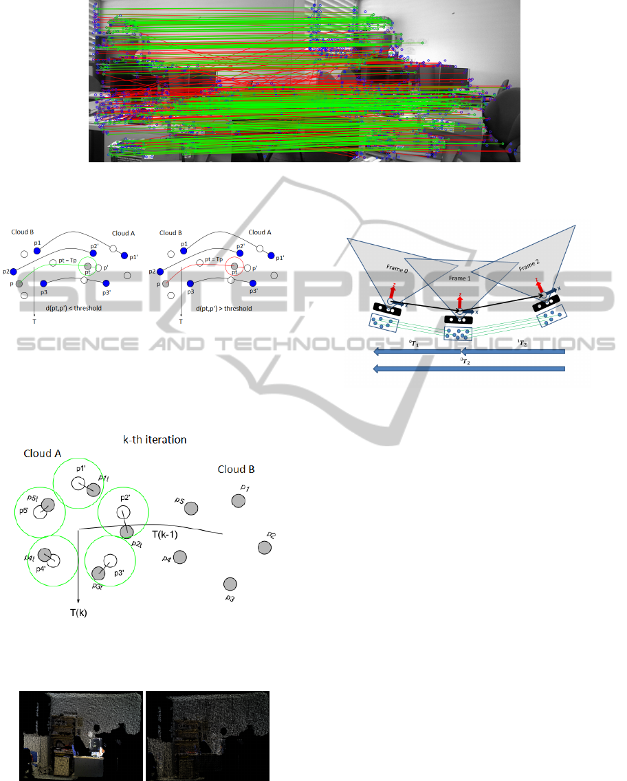
Figure 4: Matches of 2D descriptors. The green lines join good correspondences and the red lines the matches rejected with
the Fundamental Matrix constraint and RANSAC.
Figure 5: Checking of outliers using the 3D matrix trans-
formation with the distance from p
j
to the transformed cor-
responding point pt
i
= Tp
i
. Left: the distance from p
j
to
the transformed point pt
i
is lower than the threshold (in-
lier). Right: the distance from p
j
to pt
i
is bigger than the
threshold (outlier).
Figure 6: K − th iteration of the ICP. The closest neighbor
is found with the T
k−1
of the previous cloud. From here
the T
k
is computed and the process is iteratively repeated to
compute the optimal solution.
Figure 7: Original point cloud (left) and corresponding
sampled point cloud (right)
The localization and orientation of the camera respect
the local reference can be computed using the infor-
Figure 8: With transformation computed, the points of the
last images are transformed and added to the local map. The
points already existing in the local map are eliminated.
mation provided by the transformation matrix
i
T
0
.
The 3D position is obtained directly from the trans-
lation vector p and the orientation is computed with
RPY angles using the information of the rotation ma-
trix R (Equation 8).
T =
R
3x3
p
3x1
0
1x3
1
(8)
If the motion of the camera between the last two poses
is less than a threshold, the last frame captured is
eliminated and not added to the local map.
4 DISTRIBUTED GLOBAL MAP
Once the robots have built their own local map, they
start the communication process to fuse their infor-
mation and create the global map. As commented in
the introduction, one issue of relevance in multi-robot
systems is the establishment of a common reference.
Although there are several solutions to select the ori-
gin of the common reference here a particular solution
is implemented.
In order to make the reading easier, we name i, j, k
the robots in the network and r, s, u the point clouds
of each robot. The r
th
point cloud captured by the i
th
DistributedLocalizationandSceneReconstructionfromRGB-DData
381
robot is denoted as c
i
r
. The number of clouds captured
by the i
th
robot is m
i
.
The robots are scattered forming a network with
the communications described with an undirected
graph G
com
= {V
com
, E
com
}. The robot i can di-
rectly exchange information with a set of neighbors
N
i
= { j ∈ V
com
| (i, j) ∈ E
com
}. If robot i has to
exchange information with robot j and they are not
neighbors, then robot i finds the shortest path to com-
municate with robot j through their neighbors. The
idea is that the robots try to find the robots in the
network with whom they share common regions of
their local maps, although they are not neighbors in
the communication graph.
The communication between robots is established
using the ROS library (Quigley et al., 2009), in par-
ticular the messages are send through ROS topics re-
sulting in an unidirectional and streaming communi-
cation.
In the first stage, the SURF features extracted
from the local maps are used to find 2D correspon-
dences between the point clouds of all the robots in a
distributed fashion. Given robots i and j, they look for
matches between c
i
r
, r = 1..m
i
and c
j
s
, s = 1..m
j
estab-
lishing a ratio to represent the quality of the found
matches for each pair of point clouds. Each robot
stores the indexes of the point clouds r, s obtained.
One robot is selected to decide which is the robot
with the most and best ratios of correspondences,
which is chosen as the reference re f
g
. At the same
time it decides how the local maps will be combined
to obtain the global map. When the local associations
to be done are known, the corresponding transforma-
tion
s
T
r
of the local point clouds are computed with
RANSAC and ICP in a similar way as the used to
combine the point clouds in the local map. Addition-
ally as the local point clouds are referred to the local
reference re f
i
, re f
j
, this has to be considered in the
computation.
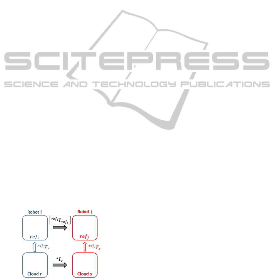
Figure 9: Transformations between the r, s point clouds of
the robots i and j and the references re f
i
, re f
j
of those
robots.
Robots have already computed the transformations of
their local point clouds to their local references,
p
re f
i
=
re f
i
T
r
· p
r
p
re f
j
=
re f
j
T
s
· p
s
(9)
As we want to compute
re f
j
T
re f
i
, we use the above
equations,
p
re f
j
=
re f
j
T
s
· p
s
=
re f
j
T
s
·
s
T
r
· p
r
=
=
re f
j
T
s
·
s
T
r
· (
re f
i
T
r
)
−1
· p
re f
i
(10)
In such a way that
re f
j
T
re f
i
=
re f
j
T
s
·
s
T
r
· (
re f
i
T
r
)
−1
(11)
Finally as the robots propagate the transformations
with their neighbors, all of them can transform their
maps to the global reference and also they can com-
pute the global map.
re f
g
T
re f
i
=
re f
g
T
re f
k
·
re f
k
T
re f
j
·
re f
j
T
re f
i
(12)
which shows the situation where robot j has the trans-
formation
re f
k
T
re f
j
and robot k has the transformation
to the global reference
re f
g
T
re f
k
.
In case one robot cannot find matches with any
other robot, its local map will not be added to the
global map, although the robot will be available for
the communications of the team, if necessary.
5 REAL EXPERIMENTS
Several experiments have been carried out with real
data. A RGB-D device in each robot is available to
get the local information. The experiments have been
accomplished in enclosed environments with different
number of robots and communication graphs. Fig-
ure 10 shows the 3D maps built by a team of five
robots. We also show the pose of the robots with
triangles in the localization where the robot has cap-
tured a RGB-D image. Once the robots have built
their own maps, they establish communication be-
tween them according to the communication graph
and then they choose as the global reference, the lo-
cal reference of the robot whose local map has the
most and best matches with the rest of maps. In this
experiment, the reference of the red robot has been
selected as the global reference frame. The next step
is to compute the transformation of each map to the
global reference as indicated in section 4. In figure 11
we show the global map obtained by the team of five
robots and their trajectories in the scene.
ICINCO2013-10thInternationalConferenceonInformaticsinControl,AutomationandRobotics
382
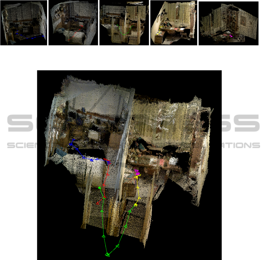
Figure 10: Local 3D map built by each robot of a team that contains the environment explored. The lines in different colors
are the trajectories followed by robots, and the triangles represent the camera poses from which a RGB-D image has been
captured.
Figure 11: Global 3D map obtained by 5 robots visiting some rooms of a house. The trajectory of each robot is represented
in different colors (red, blue, green, yellow and magenta).
In the implementation, each local maps has approx-
imately 200.000 points and the global map 800.000
points. These maps are downsampled in order to de-
crease the memory use and the computation time of
the communication process. The time needed to add a
new point cloud to the local map is in average around
600 milliseconds, so the maps can be carried out in
real time. The computation of the global map is in av-
erage 60 seconds and it’s made once the robots have
constructed their local maps.
All the experiments have been carried out using
a computer with an Intel Core i7-3630QM processor
and 6 Gb of RAM.
6 CONCLUSIONS
In this work we have presented a distributed method
to make every robot in the network compute simulta-
neously the global map and the localization of every
robot.
Our method allows each robot to build its local
map and compute its trajectory in a robust and effi-
cient way. After that, robots communicate with their
DistributedLocalizationandSceneReconstructionfromRGB-DData
383

neighbors and find the best global reference frame.
All robots transform their maps to this global frame
and finally they obtain a common global map.
The information used is RGB-D data. This makes
possible to obtain accurate 3D information of the
scene. The huge amount of data managed introduces
the necessity of using 2D descriptors in some steps of
the matching process. The real results presented show
the goodness of the computed map.
ACKNOWLEDGEMENTS
This work was supported by projects Ministerio
de Econom
´
ıa y Competitividad / Uni
´
on Europea
DPI2009-08126, DPI2012-32100.
REFERENCES
Alriksson, P. and Rantzer, A. (2006). Distributed Kalman
filtering using weighted averaging. In Int. Symposium
on Mathematical Theory of Networks and Systems,
Kyoto, Japan.
Bailey, T., Nebot, E. M., Rosenblatt, J. K., and Durrant-
Whyte, H. (2000). Data association for mobile robot
navigation: a graph theoretic approach. In IEEE Int.
Conf. on Robotics and Automation, pages 2512–2517,
San Francisco, USA.
Bay, H., Tuytelaars, T., and Gool, L. V. (2006). Surf:
Speeded up robust features. In European Conference
on Computer Vision, pages 404–417.
Besl, P. J. and Mckay, H. D. (1992). A method for regis-
tration of 3-D shapes. Pattern Analysis and Machine
Intelligence, IEEE Transactions on, 14(2):239–256.
Bullo, F., Cort
´
es, J., and Mart
´
ınez, S. (2009). Distributed
Control of Robotic Networks. Applied Mathemat-
ics Series. Princeton University Press. Electronically
available at http://coordinationbook.info.
Calafiore, G. and Abrate, F. (2009). Distributed linear es-
timation over sensor networks. International Journal
of Control, 82(5):868–882.
Carpin, S. (2008). Fast and accurate map merging for multi-
robot systems. Autonomous Robots, 25(3):305–316.
Fischler, M. A. and Bolles, R. C. (1981). Random sample
consensus: a paradigm for model fitting with appli-
cations to image analysis and automated cartography.
Commun. ACM, 24(6):381–395.
Fox, D., Ko, J., Konolige, K., Limketkai, B., Schulz, D., and
Stewart, B. (2006). Distributed multirobot exploration
and mapping. IEEE Proceedings, 94(7):1325–1339.
Gil, A., Reinoso, O., Ballesta, M., and Julia, M. (2009).
Multi-robot visual SLAM using a rao-blackwellized
particle filter. Robotics and Autonomous Systems,
58(1):68–80.
Kaess, M. and Dellaert, F. (2009). Covariance recov-
ery from a square root information matrix for data
association. Robotics and Autonomous Systems,
57(12):1198–1210.
Lynch, K. M., Schwartz, I. B., Yang, P., and Freeman,
R. A. (2008). Decentralized environmental model-
ing by mobile sensor networks. IEEE Transactions
on Robotics, 24(3):710–724.
Muja, M. and Lowe, D. G. (2009). Fast approximate near-
est neighbors with automatic algorithm configuration.
In VISAPP International Conference on Computer Vi-
sion Theory and Applications, pages 331–340.
Neira, J. and Tard
´
os, J. D. (2001). Data association
in stochastic mapping using the joint compatibility
test. IEEE Transactions on Robotics and Automation,
17(6):890–897.
Olfati-Saber, R. (2007). Distributed Kalman filtering for
sensor networks. In IEEE Conf. on Decision and Con-
trol, pages 5492–5498, New Orleans, LA.
Parker, L. E. (2000). Current state of the art in distributed
robotic systems. In Parker, L. E., Bekey, G., and
Barhen, J., editors, Distributed Autonomous Robotic
Systems 4, pages 3–12. Springer Verlag.
Quigley, M., Conley, K., Gerkey, B. P., Faust, J., Foote, T.,
Leibs, J., Wheeler, R., and Ng, A. Y. (2009). ROS: an
open-source Robot Operating System. In ICRA Work-
shop on Open Source Software.
Sagues, C., Murillo, A. C., Guerrero, J. J., Goedem
´
e, T.,
Tuytelaars, T., and Gool, L. V. (2006). Localization
with omnidirectional images using the 1D radial tri-
focal tensor. In IEEE Int. Conf. on Robotics and Au-
tomation, pages 551–556, Orlando, USA.
Thrun, S. and Liu, Y. (2003). Multi-robot SLAM with
sparse extended information filters. In Int. Symposium
of Robotics Research, pages 254–266, Sienna, Italy.
Xiao, L., Boyd, S., and Lall, S. (2005). A scheme for ro-
bust distributed sensor fusion based on average con-
sensus. In Information Processing in Sensor Net-
works, 2005. IPSN 2005. Fourth International Sym-
posium on, pages 63–70.
ICINCO2013-10thInternationalConferenceonInformaticsinControl,AutomationandRobotics
384
