
Using SoaML Models and Event-B Specifications for Modeling SOA
Design Patterns
Imen Tounsi
1
, Zied Hrichi
1
, Mohamed Hadj Kacem
1
, Ahmed Hadj Kacem
1
and Khalil Drira
2,3
1
ReDCAD-Research unit, University of Sfax, Sfax, Tunisia
2
CNRS, LAAS, 7 avenue du colonel Roche, F-31400 Toulouse, France
3
Univ. de Toulouse, LAAS, F-31400 Toulouse, France
Keywords:
SOA Design Patterns, SoaML Modeling, Formal Methods, Event-B Method, Tool Support.
Abstract:
Although design patterns have become increasingly popular, most of them are presented in an informal way.
Patterns, proposed by the SOA design pattern community, are described with a proprietary informal notation,
which can raise ambiguity and may lead to their incorrect usage. Modeling SOA design patterns with a
standard formal notation avoids misunderstanding by software architects and helps endow design methods. In
this paper, we present an approach that aims, first, to model message-oriented SOA design patterns with the
SoaML language, and second to transform them to Event-B specifications. These two steps are performed
before undertaking the effective coding of a design pattern providing correct by construction pattern-based
software architectures. Our approach is enhanced with a tool supporting it. Specification results are imported
under the Rodin platform which we use to prove model consistency.
1 INTRODUCTION
The dominant architectural style for many systems is
the Service-oriented architecture (SOA), a style that
is essentially based on the message exchange. This ar-
chitecture offers a model and an opportunity to solve
problems related to the communication and the inte-
gration between heterogeneous and distributed appli-
cations (Erl, 2009). However these architectures are
subject to some quality attribute failures (e.g., avail-
ability, reliability, and performance problems). De-
sign patterns, as tested solutions to common design
problems within a context, have been widely used to
solve these weaknesses.
Patterns, proposed by the SOA design pattern
community, are described with a proprietary infor-
mal notation (Erl, 2009), which can raise ambiguity
and may lead to their incorrect usage. So they require
modeling with a standard notationand then formaliza-
tion. The intent of our approach is to model and for-
malize message-oriented SOA design patterns. These
steps are performed before undertaking the effective
coding of a design pattern, so that the pattern in ques-
tion will be correct by construction. Our approach al-
lows to reuse correct SOA design patterns, hence we
can save effort on proving pattern correctness.
The main idea underlying our approach has been
introduced in (Tounsi et al., 2013b). In (Tounsi
et al., 2013a) we presented the generic formalization
of SOA design patterns using the Event-B method. In
this paper, we present transformation rules for map-
ping SoaML pattern diagrams into Event-B pattern
specifications and how they are implemented. We
proceed by proposing the SOA design patterns mod-
eling. This modeling step is proposed in order to at-
tribute a standard notation to SOA design patterns.
Then we propose the transformation of design pattern
models, according to transformation rules, into Event-
B specifications. We import the generated specifica-
tions under the Rodin platform which we use to prove
model consistency. We provide structural features of
SOA design patterns in the modeling phase as well
as in the specification phase. Structural features of
a design pattern are generally specified by assertions
on the existence of types of components in the pat-
tern. The configuration of the elements is also de-
scribed, in terms of the static relationships between
them. We illustrate our approach through a pattern
example “Event-Driven Messaging”, proposed by the
SOA design pattern community. We also present a
tool supporting our approach.
The paper is structured as follows. Section 2 gives
294
Tounsi I., Hrichi Z., Hadj Kacem M., Hadj Kacem A. and Drira K..
Using SoaML Models and Event-B Specifications for Modeling SOA Design Patterns.
DOI: 10.5220/0004453302940301
In Proceedings of the 15th International Conference on Enterprise Information Systems (ICEIS-2013), pages 294-301
ISBN: 978-989-8565-60-0
Copyright
c
2013 SCITEPRESS (Science and Technology Publications, Lda.)

background information of some concepts used in this
paper. Section 3 gives an overview of our approach.
Section 4 describes our tool supporting our approach.
Section 5 discusses related work. Section 6 concludes
and gives future works.
2 BACKGROUND
In following, we provide background information on
patterns, XSLT language and Event-B method.
2.1 Design Patterns
In the field of information systems, a pattern is de-
fined as a model that provides a proven solution to a
common problem individually documented in a con-
sistent format and usually as part of a larger collec-
tion (Erl, 2009). Patterns can be classified relatively
to their level of abstraction into three categories:
architectural patterns that provide the skeleton for
the overall shape and the structure of software appli-
cations at a high-level design (Gomaa, 2004), design
patterns that encode a proven solution to a recurring
design common problem (Ramirez and Cheng, 2009),
and implementation patterns that provide a solution
to a given problem in programming (Beck, 2007). It
is used to generate code.
2.2 XSLT
XSLT
1
(eXtensible Styles Language Transformation)
is a W3C standard that supports the XML standard.
The objective of this specification is to transform
XML documents into another document format. XSL
is decomposed into two languages, a transformation
language and a formatting language. The first one can
transform an XML document into another document,
while the second one can use predefined tags to rep-
resent the visual aspect of an XML document. XSLT
apply the transformation written by XSL stylesheet to
an XML document.
2.3 Event-B
Event-B (Abrial, 2010) is a formal method for devel-
oping systems via stepwise refinement, based on first-
order logic. The method is enhanced by its supporting
Rodin Platform (Abrial et al., 2010) for analyzing and
reasoning rigorously about Event-B models. The ba-
sic concept in the Event-B development is the model
which is made of two types of components: contexts
1
http ://www.w3.org/TR/xslt
and machines. A context describes the static part of a
model, whereas a machine describes the dynamic be-
havior of a model. Each context has a name and other
clauses like ”Constants” to declare constants, ”Sets”
to declare a new data type and ”Axioms” that denotes
the type of the constants and the various predicates
which the constants obey. It is a predicate that is as-
sumed to be true in the rest of the model.
3 APPROACH OVERVIEW
The main goal of our approach is the modeling of
message-oriented SOA design patterns with the semi-
formal SoaML
2
standard language, the automatic
transformation of pattern diagrams to Event-B spec-
ifications and the formal verification of their correct-
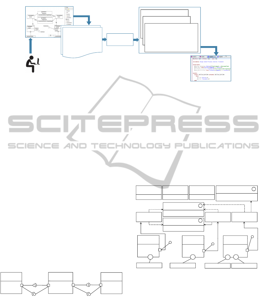
ness. Figure 3 depicts the overall approach.
After modeling design patterns, the graphical ed-
itor generates an XML file. The plug-in transforms
this XML file, according to transformation rules ex-
pressed with the XSLT language, into Event-B spec-
ifications. These specifications will then be imported
under the Rodin theorem prover that supports the gen-
eration of Proof Obligations belonging to Event-B
models. The Rodin Platform is also used in order to
check the syntax of SOA design pattern specifications
as well as their correctness.
3.1 SOA Design Patterns Modeling
We provide a modeling solution for describing SOA
design patterns using a visual notation based on the
graphical SoaML language. Three main reasons lead
to use SoaML. First, it is a standard modeling lan-
guage defined by OMG. Second, it is used to describe
service oriented architectures. Third, diagrams used
in SoaML, allow to represent structural features as
well as behavioral features of design patterns.
The SoaML metamodel extends the UML meta-
model to support an explicit service modeling in dis-
tributed environments. This extension is perfectly ap-
plied to SOA design patterns modeling. We model
structural features of design patterns with Participant
diagram, ServiceInterface diagram, MessageType di-
agram.
In this paper, we model as example the
Event
Driven Messaging pattern
3
(Erl, 2009). It is
an SOA design pattern for inter-service message ex-
change. It resolves the problem of inefficient polling-
based interactions for service consumer, generated in
2
http ://www.omg.org/spec/SoaML/
3
http ://soapatterns.org/patterns/event
driven messaging
UsingSoaMLModelsandEvent-BSpecificationsforModelingSOADesignPatterns
295
EVENT Sending_Req
Where
CONSTANTS
RequestMessage
ResponseMessage
AXIOMS
Message_partition :
partition(MessageType,
EVENT Receiving_Resp
Where
CONSTANTS
RequestMessage
ResponseMessage
AXIOMS
Message_partition :
partition(MessageType,
Transformation
Rules
2.Transformation
Graphical editor
3.Generate Event-B specifications
SETS
MessageType.
CONSTANTS
RequestMessage
ResponseMessage
AXIOMS
Message_partition : partition(MessageType,
RequestMessage},{ResponseMessage})
1.Edit models
XML documents
фWĂƌƚ͗ZŽŽƚ džŵŝ͗ǀĞƌƐŝŽŶсΗϮ͘ϬΗEĂŵĞсΗΗх
ф
WĂƌƚŝĐŝƉĂŶƚ WĂƌƚŝĐŝƉĂŶƚEĂŵĞсΗ^ĞƌǀŝĐĞΗх
ф
WŽƌƚх
ф
^ĞƌǀŝĐĞWŽƌƚ EĂŵĞсΗ͗^ĞƌǀŝĐĞyΗͬх
фͬ
WŽƌƚх
фͬ
WĂƌƚŝĐŝƉĂŶƚх
ф
WĂƌƚŝĐŝƉĂŶƚ WĂƌƚŝĐŝƉĂŶƚEĂŵĞсΗ^ĞƌǀŝĐĞŽŶƐƵŵĞƌΗх
ф
WŽƌƚх
ф
ZĞƋƵĞƐƚWŽƌƚ EĂŵĞсΗ͗Ε^ĞƌǀŝĐĞyΗͬх
фͬ
WŽƌƚх
фͬ
WĂƌƚŝĐŝƉĂŶƚх
ф
WĂƌƚŝĐŝƉĂŶƚ WĂƌƚŝĐŝƉĂŶƚEĂŵĞсΗĂĐŬͲƵƉ^ƚŽƌĞƐΗх
ф
WŽƌƚх
фWĂƌƚ͗ZŽŽƚ džŵŝ͗ǀĞƌƐŝŽŶсΗϮ͘ϬΗEĂŵĞсΗΗх
ф
WĂƌƚŝĐŝƉĂŶƚ WĂƌƚŝĐŝƉĂŶƚEĂŵĞсΗ^ĞƌǀŝĐĞΗх
ф
WŽƌƚх
ф
^ĞƌǀŝĐĞWŽƌƚ EĂŵĞсΗ͗^ĞƌǀŝĐĞyΗͬх
фͬ
WŽƌƚх
фͬ
WĂƌƚŝĐŝƉĂŶƚх
ф
WĂƌƚŝĐŝƉĂŶƚ WĂƌƚŝĐŝƉĂŶƚEĂŵĞсΗ^ĞƌǀŝĐĞŽŶƐƵŵĞƌΗх
ф
WŽƌƚх
ф
ZĞƋƵĞƐƚWŽƌƚ EĂŵĞсΗ͗Ε^ĞƌǀŝĐĞyΗͬх
фͬ
WŽƌƚх
фͬ
WĂƌƚŝĐŝƉĂŶƚх
ф
WĂƌƚŝĐŝƉĂŶƚ WĂƌƚŝĐŝƉĂŶƚEĂŵĞсΗĂĐŬͲ
фWŽƌƚх
4. Proof Obligations
R
ŽĚŝŶ
User
Figure 1: The overall approach.
order to obtain information about events occurrence.
The solution proposed by this pattern is to introduce
an event manager allowing the service consumer to
set itself up as a subscriber to events associated with a
service that assumes the role of publisher. So that ser-
vice consumers are automatically notified of runtime
service events.
We specify entities of the pattern and their depen-
dencies (connections) in the Participant diagram (Fig-
ure 2) and we specify their interfaces and exchanged
messages in the ServiceInterface and MessageType
diagrams respectively (Figure 3).
The Subscriber, the Publisher and the Event-
Manager are defined as participants because they pro-
vide and use services. As shown in Figure 2, the
Publisher provides an event used by the Subscriber.
When the event occurs, the Publisher automati-
cally sends the event details to the Event-Manager,
which then broadcasts the event notification to the
Subscriber. Both the Publisher and the Subscriber
have a port typed with “Event”. the Publisher is the
provider of the service and has a Service port. The
Subscriber is a consumer of the service and uses a Re-
quest port. In this diagram, ServiceChannels are ex-
plicitly represented, they enables communication be-
tween the different participants.
« Participant »
Publisher
« Participant »
Event_Manager
«ServiceChannel»
PushEM_P
« Participant »
Subscriber
«ServiceChannel»
PushS_EM
« Service »
: Event_Notif
«ServiceChannel»
« Service » :
Event
« Request »
: ~ Event
«
ServiceChannel
»
PushP_EM
«
ServiceChannel
»
PushEM_S
Figure 2: Participant diagram.
In the MessageType diagram (Figure 3) three
MessageTypes are used to define information ex-
changed between the Publisher, the Subscriber and
the Event-Manager. These messages are “
SubsReq
”,
“
SubsResp
” and “
EventInfo
”, they are used as types
for operation parameters of the service interfaces. As
shown in Figure 3, the Publisher’s port type is the
UML interface “
ProviderEvent
” that has the opera-
tion “
publishEvent
”. This operation has a message
style parameter typed “
EventInfo
”. The Subscriber
expresses its request for the “Event” using its request
port. The type of this request port is the UML in-
terface “
SubscriberEvent
”. This interface has an
operation “
subscribeEvent
” with a parameter typed
“
SubsReq
”. The type of the Event-Manager’s port
is the UML interface “
Notification
” that has two
operations “
eventNotif
” and “
subsNotif
”. These
operations have two message style parameters where
the type of the parameters are the MessageTypes
“
SubsResp
” and “
EventInfo
”.
«MessageType»
SubsReq
«MessageType»
EventInfo
«MessageType»
SubsResp
« Interface »
Notification
+ subsNotif (snotif: SubsResp)
« Interface »
SubscriberEvent
«use»
+ eventNotif (enotif: EventInfo)
«use»
« Interface »
ProviderEvent
+ subscribeEvent (rq:SubsReq)
«ServiceInterface»
~ Event
«ServiceInterface»
Event
«ServiceInterface»
Event_Notif
+ publishEvent(rs:EventInfo)
«Participant»
«Participant»
«use»
Type
Type
«Participant»
Notification
Type
«Participant»
Subscriber
SubscriberEvent
«Participant»
Publisher
ProviderEvent
«Participant»
Event_Manager
«Request»
: ~ Event
+
subscribeEvent
«Service»
: Event
bli hE t
+
b N tif
+
«Service»
: Event_Notif
tN tif
+
subscribeEvent
p
u
bli
s
hE
ven
t
su
b
s
N
o
tif
even
tN
o
tif
Figure 3: ServiceInterface and MessageType diagrams.
3.2 SOA Design Patterns
Transformation
In the SOA design patterns transformation step, we
present the transformation process of SoaML dia-
grams to Event-B language.
3.2.1 Participant Diagram Mapping
This diagram constitute the static part of the defined
pattern. It is specified in the Context part. The trans-
ICEIS2013-15thInternationalConferenceonEnterpriseInformationSystems
296

formation of the Participant diagram is based on four
major rules allowing the transformation of a graphical
model into an Event-B specification.
R1. Architecture Entities Transformation Rule
This rule transforms entity types into new Event-B
entity types. Participant names and agent names are
transformed to constants. The set Entity is composed
of the set of all Participants and the set of all Agents.
This is specified by using a partition in the
AXIOMS
clause (Entity partition). The following algorithm
shows how to transform the architecture entities.
Algorithm 1: Architecture entities transformation rule.
1: begin
2: Write (” SETS ”)
3: Write (‘Entity’)
4: Write (” CONSTANTS ”)
5: if exist Participant then
6: Write (‘Participant’)
7: for each Participant do
8: Write (Participant.Name)
9: end for
10: end if
11: if exist Agent then
12: Write (‘Agent’)
13: for each Agent do
14: Write (Agent.Name)
15: end for
16: end if
17: Write (” AXIOMS ”)
18: Write (‘Entity
partition:partition(Entity’)
19: if exist Participant then
20: Write(‘,Participant’)
21: end if
22: if exist Agent then
23: Write(‘,Agent’)
24: end if
25: if exist Participant then
26: Write(‘Participant
partition (Participant,’)
27: for each Participant do
28: Write (Participant.Name)
29: end for
30: end if
31: if exist Agent then
32: Write(‘Agent
partition (Agent,’)
33: for each Agent do
34: Write (Agent.Name)
35: end for
36: end if
37: end
R2. Connections Transformation Rule
In the SoaML modeling, a ServiceChannel is a
connection between two architecture entities. This
rule define the graphical connection with an Event-
B relation between two entities (ServiceChannel)
and transforms ServiceChannels name into con-
stants in the
CONSTANTS
clause. The set of Ser-
viceChannels is composed of all ServiceChannel’s
name. This is transformed formally to a partition
(ServiceChannel partition). This rule also generates
Domain and Range axioms for each service channel
to define its source and its target. The following algo-
rithm shows how to transform a service channel.
Algorithm 2: Connections transformation rule.
1: begin
2: Write (” CONSTANTS ”)
3: if exist ServiceChannel then
4: Write (’ServiceChannel’)
5: for each ServiceChannel do
6: Write (ServiceChannel.Name)
7: end for
8: end if
9: Write (” AXIOMS ”)
10: if exist ServiceChannel then
11: Write(’ServiceChannel
partition:partition(ServiceChannel’)
12: for each ServiceChannel do
13: Write (ServiceChannel.Name)
14: end for
15: Write(’ServiceChannel
Relation : ServiceChannel ∈ Entity ↔
Entity’)
16: for each ProviderInterface do
17: Write (ProviderInterface.Origine)
18: Write(’
Domain:dom’)
19: Write (({ProviderInterface.Origine}))
20: Write(’=’)
21: Write ({ProviderInterface.Destinataire})
22: end for
23: for each RequireInterface do
24: Write (RequireInterface.Destinataire)
25: Write(’
Range:ran’)
26: Write (({RequireInterface.Destinataire}))
27: Write(’=’)
28: Write ({RequireInterface.Origine})
29: end for
30: end if
31: end
R3. Class Descriptions Transformation Rule
This rule transforms catalog type to a new Event-B
catalog type and catalogs name into constants in the
CONSTANTS
clause. The set of Catalogs is composed
of all catalogs name. This is transformed formally to
a partition (Catalog
partition). This rule also trans-
forms category type to a new Event-B category type
and categories name into constants in the
CONSTANTS
clause. The set of Categories is composed of all Cat-
egories name. This is transformed formally to a par-
tition (Category
partition). The relation of contain-
ment of a Catalog with Categories is transformed to
the relation Belongs
to. The link ofCategorization is
transformed to a relation between a Category and an
Entity. The following algorithm shows how to trans-
form class descriptions.
UsingSoaMLModelsandEvent-BSpecificationsforModelingSOADesignPatterns
297

Algorithm 3: Class descriptions transformation rule.
1: begin
2: Write (” SETS ”)
3: if exist Catalog then
4: Write (’Catalog’)
5: end if
6: if exist Category then
7: Write (’Category’)
8: end if
9: Write (” CONSTANTS ”)
10: if exist Catalog then
11: for each Catalog do
12: Write (Catalog.Name)
13: end for
14: end if
15: if exist Category then
16: for each Category do
17: Write (Category.Name)
18: end for
19: end if
20: if exist Category and exist Catalog then
21: Write (’Belongs
To’)
22: Write (’Categorization’)
23: end if
24: Write (” AXIOMS ”)
25: if exist Catalog then
26: Write(’Catalog
partition:partition(Catalog,’)
27: for each Catalog do
28: Write (Catalog.Name)
29: end for
30: end if
31: if exist Category then
32: Write(’Category
partition:partition(Category,’)
33: for each Category do
34: Write (Category.Name)
35: end for
36: Write(’Belongs
to Relation : Belongs to ∈ Catalog ↔ Category’)
37: Write(’Categorization :Categorization ∈ Category ↔ Entity’)
38: Write (’Belongs
to init:Belongs to = {’)
39: for each Category do
40: for each Catalog do
41: Write (Catalog.Name)
42: Write(’7→’)
43: Write (Category.Name)
44: end for
45: end for
46: Write (’}’)
47: Write (’Categorization
init:Categorization = {’)
48: for each Categorization do
49: Write (Categorization.TransitionToNoeud)
50: Write(’7→’)
51: Write (Categorization.TransitionFromNoeud)
52: end for
53: Write (’}’)
54: end if
55: end
R4. Capabilities Transformation Rule
This rule transforms capability type to a new Event-B
capability type and capability name into constants in
the
CONSTANTS
clause. The set of Capabilities is com-
posed of all capabilities name. This is transformed
formally into a partition (Capability partition). The
link between a Participant and a capability is trans-
formed to a relation Provide. The followingalgorithm
shows how to transform capabilities.
Algorithm 4: Capabilities transformation rule.
1: begin
2: Write (” SETS ”)
3: if exist Capability then
4: Write (’Capability’)
5: end if
6: Write (” CONSTANTS ”)
7: if exist Capability then
8: for each Capability do
9: Write (Capability.Name)
10: Write (’Provide’)
11: end for
12: end if
13: Write (” AXIOMS ”)
14: if exist Capability then
15: Write(’Capability
partition:partition(Capability,’)
16: for each Capability do
17: Write (Capability.Name)
18: end for
19: Write(’Provide
Relation : Provide ∈ Participant ↔ Capability’)
20: Write(’Capability
init:Capability={’)
21: for each Realization do
22: Write (Realization.TransitionFromProperty)
23: Write(’7→’)
24: Write (Realization.TransitionToCapability)
25: end for
26: Write (’}’)
27: end if
28: end
3.2.2 MessageType Diagram Mapping
This diagram is also specified in theContext part. The
transformation of this diagram is based on a single
rule that allows to transform the graphical model into
an Event-B specification. This rule transforms Mes-
sageType to a new Event-B message type and mes-
sages name into constants in the
CONSTANTS
clause.
The set of MessageType is composed of all messages
name. This is transformed formally to a partition
(Message
partition). The following algorithm shows
how to transform MessageTypes.
3.2.3 Service Interface Diagram Mapping
This diagram is specified in the same Context. The
transformation rule of this diagram define the relation
Can Send, which is the link between an Entity and a
MessageType. The following algorithm shows how
to transform Service Interfaces.
ICEIS2013-15thInternationalConferenceonEnterpriseInformationSystems
298
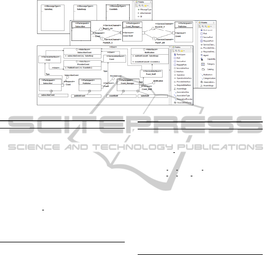
Figure 4: SOA design patterns plug-in.
Algorithm 5: MessageType transformation rule.
1: begin
2: Write (” SETS ”)
3: if exist Message then
4: Write (’MessageType’)
5: end if
6: Write (” CONSTANTS ”)
7: if exist Message then
8: for each MessageType do
9: Write(MessageType.Name)
10: end for
11: end if
12: Write (” AXIOMS ”)
13: if exist Message then
14: Write(’Message
partition:partition(MessageType’)
15: for each MessageType do
16: Write (,{ MessageType.Name})
17: end for
18: end if
19: end
4 TOOL SUPPORT
Our approach is enhanced by an Eclipse plug-
in based on its development on the Frameworks;
GMF (Graphical Modeling Framework) (Eclipse,
2010b), EMF (Eclipse Modeling Framework) (Stein-
berg et al., 2009) and GEF (Graphical Editing
Framework) (Eclipse, 2010a). It is a graphical mod-
eling tool that ensures an easy and efficient modeling
way of SOA design patterns. Several diagrams are
available in the plug-in; we can model Participant
diagram, Service Inter face diagram, and Message
Type diagram.
The SOA design patterns diagram editor is a tool
where diagrams can be created to model patterns. Fig-
Algorithm 6: Service Interface transformation rule.
1: begin
2: Write (” CONSTANTS ”)
3: if exist Participant then
4: Write (’Can
Send’)
5: end if
6: Write (” AXIOMS ”)
7: Write(’Can
Send Relation :Can Send ∈ Entity ↔ MessageType’)
8: Write(’Can
Send init:Can send = {’)
9: Var1 ← Participant.RequestPort.Name
10: Var2 ← ServiceInter face.Name
11: Var3 ← AssociationUse.Origine
12: for each Participant do
13: Write(Participant.Name)
14: Write(’7→’)
15: if Var1 = Var2 and Var1 = Var3 then
16: Select(AssociationUse.Destinataire)
17: Write(Interface.OperationInterface.Name)
18: end if
19: end for
20: Write (’}’)
21: end
ure 4 shows the diagram editor of the SOA design
patterns with an illustration of the pattern example
“Event-Driven Messaging”. After modeling a design
pattern, the plug-in generates an XML specification
describing it. The generated XML specification corre-
sponding to the participant diagram presented in Fig-
ure 2, is depicted in follows.
<!-- =======Entities======= -->
<Participant ParticipantName="Subscriber">
<Port>
<RequestPort Name=": ˜ Event"/>
</Port>
</Participant>
...
<!-- =======Connexions======= -->
<RequireInterface Origine="..." Destinataire="//@Assemblage.0"/>
<RequireInterface Origine=".../@Port.0" Destinataire="..."/>
...
UsingSoaMLModelsandEvent-BSpecificationsforModelingSOADesignPatterns
299

The plug-in transforms the generated XML file,
according to transformation rules expressed with the
XSLT language, into Event-B specifications. These
specifications can be imported under the Rodin plat-
form to verify their correctness. Transformation rules
described in section 3.2 are expressed with the XSLT
language.
By applying transformations rules on the gener-
ated XML specifications, we obtain Event-B specifi-
cations presented in Figure 5.
CONTEXT
EventDrivenM
SETS
Entity
MessageType
CONSTANTS
Participant
ServiceChannel
AXIOMS
Entity_partition: partition(Entity, Participant)
Participant_partition: partition(Participant, {Subscriber},
{Event_Manager}, {Publisher})
Message_partition: partition(MessageType, {SubsReq}, {SubsResp},
{EventInfo})
ServiceChannel_Relation: ServiceChannel א Entity ↔ Entity
ServiceChannel_partition: partition(ServiceChannel, {PushS_EM},
{
PushEM_S
}, {
PushEM_P
}, {
PushP_EM
})
ServiceChannel
Subscriber
Event_Manager
Publisher
SubsReq
EventInfo
PushS_EM
Can_Send
. . .
{
PushEM_S
}, {
PushEM_P
}, {
PushP_EM
})
PushS_EM_Domain: dom({PushS_EM}) = {Subscriber}
. . .
PushEM_S_Range:
ran({PushEM_S}) = {Subscriber}
. . .
Can_Send_Relation:
Can_Send א Entity ↔ MessageType
Can_Send_init: Can_Send = {Subscriber հ SubsReq, Publisher հ
EventInfo, Event_ManagerհSubsResp, Event_ManagerհEventInfo}
END
Figure 5: Excerpt of Event-B specification results.
5 RELATED WORK
In the literature most proposed patterns are described
with a combination of textual description and a graph-
ical presentation (Gamma et al., 1995), some times
using proprietary notations (Gregor Hohpe, 2003; Erl,
2009), in order to make them easy to read and un-
derstand. However, using these descriptions makes
patterns ambiguous and may lack details. There have
been many research that specify patterns using formal
techniques (Zhu and Bayley, 2010; Blazy et al., 2003)
but research that model design patterns with semi-
formal languages are few (Mapelsden et al., 2002).
In our research work we are interested in SOA de-
sign patterns defined by Erl (Erl, 2009). For these
patterns, there are no work that model or formally
specify them. Erl presents his patterns with an infor-
mal proprietary notation because there is no standard
modeling notation for SOA, but now OMG announces
the publication of the SoaML language (OMG, 2012).
So, in our work, we propose to model SOA design
patterns with the SoaML standard language. After
the modeling step, we propose to specify these pat-
terns formally. Similar to (Zhu and Bayley, 2010;
Kim and Carrington, 2009)we specify design patterns
using First Order Logic, but we use a different formal
method which is Event-B.
After the OMG publication of the SoaML lan-
guage, some works that provide SoaML support ap-
peared. Delegado et al. (Delgado et al., 2011) devel-
oped an Eclipse plug-in based on EMF and GMF that
implements the SoaML standard. Modeling with this
plug-in is quite heavy and we can not model a pro-
vided/required connection with SoaML. Other tools
that allow modeling service oriented architectures ac-
cording to the OMG standard exists like Modeliosoft
(Modeliosoft, 2011) and modelDriven (ModelDriven,
2009) however, these tools do not use transformation
techniques for generating formal specifications.
In this context, we proposed a tool for modeling
SOA design patterns, that is not only easy to use, spe-
cific for our diagrams, and adaptable with Rodin en-
vironment but also it allows importing and exporting
XML files of model that will be subsequently con-
verted to Event-B specifications. Moreover, we use
the XSLT language for the automatic transformation
of our model to Event-B language.
6 CONCLUSIONS
In this paper, we presented an architecture-centric ap-
proach supporting the modeling and the transforma-
tion of message-oriented SOA design patterns to for-
mal specifications. The modeling phase allows to de-
scribe SOA design patterns with a graphical standard
notation using the SoaML language. The transforma-
tion phase allows to formally specify structural fea-
tures of these patterns at a high level of abstraction.
We proposed an Eclipse plug-in that supports our ap-
proach. More precisely, it allows the modeling of
SOA design patterns and then generating the corre-
sponding XML file. Each XML file is transformed
according to transformation rules expressed with the
XSLT language into Event-B specifications. These
specifications are then imported under the Rodin plat-
form. We illustrated our approach through a pattern
example (“Event Driven Messaging”). In this pa-
per, we presented structural features of design pat-
terns, behavioral features are presented in the mod-
eling phase with sequence diagram which are then
transformed to machines in the Event-B method. Cur-
rently, we are working on defining transformation
rules in order to automate this phase.
ACKNOWLEDGEMENTS
This paper is done with the support of the Min-
istry of Higher Education and Scientific Research of
Tunisia within the Tunisian-French scientific cooper-
ation (DGRS/CNRS).
ICEIS2013-15thInternationalConferenceonEnterpriseInformationSystems
300

We would like to thank Hayfa Ben Abdallah for
her contribution.
REFERENCES
Abrial, J.-R. (2010). Modeling in Event-B: System and Soft-
ware Engineering. Cambridge University Press, New
York, NY, USA, 1st edition.
Abrial, J.-R., Butler, M., Hallerstede, S., Hoang, T. S.,
Mehta, F., and Voisin, L. (2010). Rodin: An Open
Toolset for Modelling and Reasoning in Event-B. Int.
J. Softw. Tools Technol. Transf., 12(6):447–466.
Beck, K. (2007). Implementation Patterns. Addison Wes-
ley; 1 edition (23 Oct 2007).
Blazy, S., Gervais, F., and Laleau, R. (2003). Reuse of spec-
ification patterns with the B method. In Proceedings
of the 3rd international conference on Formal spec-
ification and development in Z and B, ZB’03, pages
40–57, Berlin, Heidelberg. Springer-Verlag.
Delgado, A., Laura, G., Sofia, L., Andrs, P., FranciscoRuiz,
I., and Garcia, R. (2011). SoaML Eclipse plug-in para
modelado de servicios. Technical report, Technical
report.
Eclipse (2010a). Graphical Editing Framework. http://
www.eclipse.org/gef/.
Eclipse (2010b). Graphical Modeling Framework.
http://www.eclipse.org/modeling/gmf/.
Erl, T. w. a. c. (2009). SOA Design Patterns (The Prentice
Hall Service-Oriented Computing Series from Thomas
Erl). Prentice Hall PTR, 1 edition.
Gamma, E., Helm, R., Johnson, R. E., and Vlissides,
J. (1995). Design Patterns: Elements of Reusable
Object-Oriented Software. Addison-Wesley, Reading,
MA.
Gomaa, H. (2004). Designing Software Product Lines with
UML: From Use Cases to Pattern-Based Software Ar-
chitectures (The Addison-Wesley Object Technology
Series). Addison-Wesley Professional.
Gregor Hohpe, B. W. (2003). Enterprise Integration Pat-
terns - Designing, Building, and Deploying Messag-
ing Solutions. Addison Wesley.
Kim, S.-K. and Carrington, D. A. (2009). A formalism to
describe design patterns based on role concepts. For-
mal Asp. Comput., 21(5):397–420.
Mapelsden, D., Hosking, J., and Grundy, J. (2002). Design
pattern modelling and instantiation using DPML. In
Proceedings of the 40th International Conference on
Tools Pacific: Objects for internet, mobile and embed-
ded applications, CRPIT’02, pages 3–11. Australian
Computer Society, Inc.
ModelDriven, C. (2009). ModelDriven. http://portal.
modeldriven.org/.
Modeliosoft (2011). Modelio: The open source modeling
environement. http://modeliosoft.org/.
OMG (2012). Service oriented architecture Modeling Lan-
guage (SoaML) Specification. Technical report.
Ramirez, A. J. and Cheng, B. H. (2009). Developing and
applying design patterns for dynamically adaptive sys-
tems. Technical Report MSU-CSE-09-8, Department
of Computer Science, Michigan State University, East
Lansing, Michigan.
Steinberg, D., Budinsky, F., Paternostro, M., and Merks,
E. (2009). EMF: Eclipse Modeling Framework 2.0.
Addison-Wesley Professional, 2nd edition.
Tounsi, I., Hadj Kacem, M., Hadj Kacem, A., and Drira, K.
(2013a). An Approach for Modeling and Formaliz-
ing SOA Design Patterns. In 22nd IEEE International
Conference on Enabling Technologies: Infrastructure
for Collaborative Enterprises, WETICE 2013, Ham-
mamet, Tunisia, June 17-20, 2013. To appear.
Tounsi, I., Hadj Kacem, M., Hadj Kacem, A., Drira, K.,
and Mezghani, E. (2013b). Towards an Approach for
Modeling and Formalizing SOA Design Patterns with
Event-B. In Proceedings of the 28th Annual ACM
Symposium on Applied Computing, SAC 2013, pages
1937–1938, Coimbra, Portugal. ACM.
Zhu, H. and Bayley, I. (2010). Laws of pattern composition.
In Proceedings of the 12th international conference on
Formal engineering methods and software engineer-
ing, ICFEM’10, pages 630–645, Berlin, Heidelberg.
Springer-Verlag.
UsingSoaMLModelsandEvent-BSpecificationsforModelingSOADesignPatterns
301
