Control of Mobile Manipulator with Skid-steering Platform Moving
in Unknown Terrain in Presence of Disturbance
Alicja Mazur
1
, Jerzy Z. Sasiadek
2
and Mateusz Cholewi´nski
1
1
Wrocław University of Technology, ul. Janiszewskiego 11/17, 50-372 Wrocław, Poland
2
Carleton University, 1125 Colonel By Drive, Ottawa, Canada
Keywords:
Mobile Manipulator, Nonholonomic Constraint, Robust Control, Disturbances.
Abstract:
In this paper new approach to control of nonholonomic mobile manipulator with skid-steering platform has
been presented. For mathematical model of such object, expressed in auxiliary coordinates, control law based
on virtual force concept has been introduced. Skid-steering mobile platform is an underactuated control system
with rectangular input matrix. In our approach it was assumed that there exists additional control input, giving
additional column in input matrix and causing this matrix to be invertible. Because such actuator does not
exists in reality, therefore this input was kept equal to zero equivalently. Simulations have proved that such
method works properly in unknown terrain and in presence of disturbances.
1 INTRODUCTION
Mobile manipulator, which is the subject of consider-
ations, consists of a mobile platform and an onboard
rigid manipulating arm. Such robotic object can ex-
ecute more complicated tasks than its components.
Manipulating arm is fully controlled while mobile
platform equipped with more than one axis of fixed
wheels is an underactuated system.
Wheeled mobile platforms can be treated as inde-
pendent robots or as an transportation part of com-
plex robotic assemble, for instance mobile manipula-
tors. Depending on wheels’ type and way in which
they are fixed to the cart, motion of wheeled mobile
platforms can be realized with or without slipping ef-
fect. If no slippage effect between wheels and sur-
face occurs, then there exists an equation describing
forbidden directions for realized velocities of the sys-
tem. Such equation is called nonholonomic constraint
in platform’s motion.
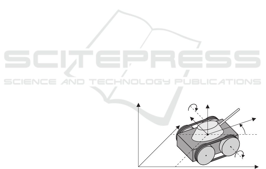
Special kind of wheeled mobile platforms are plat-
forms with tracks. They can be modeled by cart with
more than one axis equipped with fixed wheels, see
Figure 1. These platforms are called skid-steering
mobile platforms, due to skidding effect observed in
theirs behavior.
Designing control algorithms for skid-steering
platforms is a challenging task. First attempt to solve
this problem can be found in the paper (Caracci-
olo et al., 1999), in which some artificial assump-
X
0
Y
0
Z
0
X
p
Y
p
Z
p
x
y
θ
φ
2
φ
1
F
igure 1: Scheme of mobile manipulator with skid-steering
platform – tank with tracks.
tion about lateral slip during the platform’s motion
has been done. Such equation, although derived from
slipping effect, can play a role of special nonholo-
nomic constraint. Similar approach can be found in
(Kozłowski and Pazderski, 2004) or in other papers.
Another approach to the control problem for
skid-steering platform has been presented recently
in (Pazderski and Kozłowski, 2008). Authors have
treated skid-steering platform as an underactuated
system on dynamic level with non-stationary kine-
matics (non-stationary velocity constraint). They
have used tunable dynamic oscillator to get globally
uniformly bounded stability of proposed control algo-
rithm. The same idea can be found in (Mohammad-
pour et al., 2010) and (Maalouf et al., 2006).
In this paper a totally new concept for control
problem of mobile manipulator’s with skid-steering
161
Mazur A., Sasiadek J. and Cholewi
´
nski M..
Control of Mobile Manipulator with Skid-steering Platform Moving in Unknown Terrain in Presence of Disturbance.
DOI: 10.5220/0004450801610168
In Proceedings of the 10th International Conference on Informatics in Control, Automation and Robotics (ICINCO-2013), pages 161-168
ISBN: 978-989-8565-70-9
Copyright
c
2013 SCITEPRESS (Science and Technology Publications, Lda.)

platform has been presented. Mobile manipulator
with such platform can be considered as an underac-
tuated system. Till now every control algorithm pre-
sented in literature tried to avoid problem of missing
control inputs, e.g. assuming additional constraints,
because underactuated mobile platform has got rect-
angular input matrix (which is non-invertible). Prob-
lem with inverting such matrix (standing before con-
trol signals) can be solved with the idea of so-called
“virtual force”. This is a essential novelty in solution
of skid-steering mobile vehicles.
The paper is organized in the following way. In
Section 2 concept of proposed virtual force approach
to the control nonholonomic mobile manipulators is
presented. Section 3 illustrates theoretical design of
mathematical model of considered objects. In Sec-
tion 4 the control problem is formulated. In Section
5 a new control algorithm is designed. Section 6 con-
tains the simulation results. Section 7 presents some
conclusions.
2 VIRTUAL FORCE CONCEPT
In the paper a mobile manipulator with skid-steering
mobile platform has been considered. Such platform
with nonholonomic constraint for longitudinal slip-
page can be treated as an underactuated system. It
means that number of controls is smaller than number
of state variables. This results in non-square, rectan-
gular input matrix B(q) that would be impossible to
invert and would cause difficulties in control of mo-
bile manipulator dynamics.
In order to solve this problem a new method to
nonholonomic system control based on so-called “ar-
tificial force” is presented in this paper. Additional
input, further in the text called “artificial force”, is
added to existing controls to make B(q) square and
invertible. In reality, such artificial forces do not exist
with physical systems and therefore, those forces are
assumed to be equal to zero equivalently.
u
v,i
≡ 0, i = 1,... ,k. (1)
The above equations (1) describing artificial
forces are equations with implicit functions. These
functions depend on state variables, controller gains
and desired trajectories. From these equations miss-
ing reference signals could be calculated. It is pos-
sible to solve those equations with different control
algorithms. In this paper it was demonstrated how it
can work for skid-steering platform.
Similar approach was used for inverse kinematic
problem of redundant manipulators (non-square Ja-
cobi matrix) with an extended Jacobian (Baillieul,
1985), (Baillieul, 1986) and to solve the control prob-
lem of underactuated system – for an inverted pen-
dulum mounted on unicycle vehicle by (Mazur and
Ke¸dzierski, 2008).
3 MATHEMATICAL MODEL
OF MOBILE MANIPULATOR
Lets consider rigid manipulator mounted on the skid-
steering mobile platform with two axes of fixed
wheels, presented in Figure 1. State of such ob-
ject can be described by vector of platform’s general-
ized variables q
m
and manipulator’s variables q
r
, i.e.
q
T
= (q
m
,q
r
)
q
T
m
=
x y θ φ
1
φ
2
,
q
T
r
=
q
1
q
2
... q
p
,
where (x, y) are position coordinates of mass center
expressed in global frame X
0
Y
0
, θ is an orientation of
skid-steering platform, φ
i
is an angle of rotation of
wheels located on the right or the left side, whereas
q
r
is a vector of manipulator joint variables. For gen-
eralized velocities of the skid-steering platform there
exists a relationship (Kozłowski and Pazderski, 2004)
˙q
m
=
˙x
˙y
˙
θ
= Rot(z,θ)
v
x
v
y
ω
.
Symbols v
x
and v
y
mean elements of linear velocity
projected on local axes X
p
and Y
p
while ω is angular
velocity of the skid-steering mobile platform.
In this paper an assumption only about wheels mo-
tion without longitudinal slippage was made. More-
over, it was assumed that velocity of considered mo-
bile manipulator is small, not exceeding 10 [
km
h
].
All wheels of mobile platform are identical, there-
fore constraints related to absence of longitudinal
slippage can be expressed as follows
˙
φ
1r
= v
x
+ cω right side of the platform, (2)
˙
φ
2r
= v
x
− cω left side of the platform, (3)
where r is a radius of wheel and c is a half of plat-
form width. Equations (2)-(3) describing nonholo-
nomic constraints can be expressed in so-called Pfaf-
fian form in the following way
A(q
m
) ˙q
m
=
cosθ sinθ −c −r 0
cosθ sinθ c 0 −r
˙x
˙y
˙
θ
˙
φ
1
˙
φ
2
= 0. (4)
ICINCO2013-10thInternationalConferenceonInformaticsinControl,AutomationandRobotics
162

3.1 Model in Generalized Coordinates
A complex object, which is the mobile manipulator,
can include holonomic or nonholonomic subsystems.
If any nonholonomic subsystem is present then whole
robotic object must be treated as nonholonomic sys-
tem. Dynamics of such systems can be obtained from
d’Alembert principle as
M(q) ¨q +C(q, ˙q) ˙q+ D(q) + F(q, ˙q) =
= B(q)u+ A
T
(q
m
)λ. (5)
Dynamics (5) can be presented more in detail as
M
11
M
12
M
21
M
22
¨q
m
¨q
r
+
C
11
C
12
C
21
C
22
˙q
m
˙q
r
+
0
D
+
F
0
=
B 0
0 I
u
m
u
r
+
A
T
λ
0
.
Symbol M(q) denotes inertia matrix of whole mo-
bile manipulator, matrix C(q, ˙q) describes Coriolis
and centripetal forces, vector D(q) is a vector of grav-
ity (only for manipulator because platform moves on
horizontal equipotential surface), while vector F(q, ˙q)
is a vector of non-potential forces, mostly reaction
forces of terrain and friction forces. Torques B(q)u
represent control inputs (actuators) whereas A
T
λ are
forces coming from nonholonomic constraints. Input
matrix B(q) describes relationship between input sig-
nals u and control torques
B· u
m
=
0 0 −sinθ
0 0 cosθ
0 0 0
1 0 0
0 1 0
u
1
u
2
u
v
.
Symbols u
1
and u
2
denote control signal associated
with coupled wheels on the right and left side of the
skid-steering mobile platform. Third column of ma-
trix B(q) is responsible for hypothetical virtual force
u
v
, influenced by platform orientation.
3.2 Model in Auxiliary Velocities
Mobile manipulator with skid-steering mobile plat-
form is a control system with nonholonomic con-
straints. These constraints can be transformed to aux-
iliary velocities η
˙q
m
= G(q)η
=
cosθ cosθ − sinθ
sinθ sinθ cosθ
1
c
−
1
c
0
0
2
r
0
2
r
0 0
η
1
η
2
η
3v
(6)
where η
1
, η
2
are scaled wheels velocities on right and
left side of the mobile platform and η
3
is hypothetical
velocity of orientation changes.
In turn, dynamics expressed in auxiliary velocities
for nonholonomic skid-steering platform have a form
M
∗
˙
η
¨q
r
+C
∗
η
˙q
r
+
0
D
+
F
∗
0
= B
∗
u
m
u
r
,
(7)
where:
M
∗
=
G
T
M
11
G G
T
M
12
M
21
G M
22
,
C
∗
=
G
T
(C
11
G+ M
11
˙
G) G
T
C
12
M
21
˙
G+C
21
G C
22
,
F
∗
= G
T
F,
B
∗
=
G
T
B 0
0 I
.
Equations (6) and (7) constitute complete model of
nonholonomic mobile manipulator with skid-steering
platform, expressed in auxiliary coordinates. This
model is a point of departure to design a control al-
gorithm based on artificial force approach.
It is worth to mention that a mobile manipulator
with a wheeled platform has a special property, which
is not valid for its subsystems, (Dule¸ba, 2000).
Property 1. For a mobile manipulator with a
wheeled nonholonomic mobile platform a skew-
symmetry between inertia matrix M
∗
and the matrix
of Coriolis and centripetal forces C
∗
does not hold
anymore. To regain the skew-symmetry, a special non-
trivial correction matrix C
K
has to be added
d
dt
M
∗
= (C
∗
+C
K
) + (C
∗
+C
K
)
T
. (8)
Any matrix, for which the relation (8) holds, can
play role of correction matrix. The following expres-
sion describing a form of C
K
matrix, e.g.
C
K
= C
T
K
=
1
2
M
∗
−C
∗
− (C
∗
)
T
should be calculated before starting the regulation
process.
4 CONTROL PROBLEM
STATEMENT
In this paper mobile manipulator with skid-steering
mobile platform is considered. Such robotic object
should move along desired trajectory without longi-
tudinal slippage of its wheels. Desired trajectory is
defined separately for each subsystem, i.e. platform
ControlofMobileManipulatorwithSkid-steeringPlatformMovinginUnknownTerraininPresenceofDisturbance
163

should move along q
md
(t) and rigid onboard manip-
ulator have to track vector of desired joint positions
q
rd
(t), defined relative to local frame of platform.
Our goal is to address the following control prob-
lem:
1. Determine control law u such that mo-
bile manipulator with skid-steering plat-
form with known dynamics follows the de-
sired trajectory even if terrain parameters
are unknown or some measurement distur-
bances occur.
2. All virtual forces have to be equal to zero,
because they do not exist in reality.
In order to design trajectory tracking controller for
considered object, it is necessary to consider a com-
plete mathematical model of the nonholonomic sys-
tem (6)-(7) expressed in auxiliary variables as a cas-
cade composed of two groups of equations: kine-
matics (nonholonomic constraints) and dynamics, see
Figure 2:
object
kinematic
controller
η
r
η
r
,
dynamic
controller
kinematics
1 stage
dynamics
2 stage
η
r
η
r
,
CASCADE
ε
u
ε
≅
Figure 2: Structure of the control algorithm (backstepping):
cascade with two stages.
For this reason the structure of the controller is di-
vided into two parts working simultaneously (back-
stepping control approach, see (Krsti´c et al., 1995)):
• kinematic controller η
r
– represents a vector
of embedded control inputs, which ensure re-
alization of the task for the kinematics (non-
holonomic constraints) if the dynamics were not
present. Such a controller generates ’velocity pro-
file’ which has to be executed in practice to realize
the trajectory tracking for nonholonomic subsys-
tem. Kinematic controller is called ‘motion plan-
ner’.
• dynamic controller – as a consequence of cas-
caded structure of the system model, the system’s
velocities cannot be commanded directly, as it is
assumed in the design of kinematic control sig-
nals, and instead they must be realized as the out-
put of the dynamics driven by u. Dynamics are
calculated for whole system, not for each subsys-
tem separately.
5 ROBUST CONTROL
ALGORITHM
As we have mentioned in previous section, con-
trol algorithm consists of two parts, i.e. kinematic
controller and dynamic controller. Both control al-
gorithms, working simultaneously, are necessary to
solve the control problem of nonholonomic mobile
manipulator.
5.1 Kinematic Control Algorithm for
Trajectory Tracking
Considering nonholonomic constraints (6), for real
case of two active controls, they are equivalent to
the unicycle model. On that basis, the kinematic
controller is suggested in the form given by Samson
and Ait-Abderrahim (Samson and Ait-Abderrahim,
1991). This algorithm allows trajectory tracking for
a simple unicycle vehicle. Unicycle velocities appro-
priate for tracking of desired trajectory q
md
are de-
scribed by the following equation (first and second
column of matrix G(q) in equation (6))
˙q
md
= G(q
d
)η
d
=
cosθ
d
cosθ
d
sinθ
d
sinθ
d
1
c
−
1
c
0
2
r
2
r
0
η
1d
η
2d
,
(9)
where η
1d
and η
2d
are desired scaled velocities for
platform wheels located on the right and left side.
Desired linear and angular velocities of skid-
steering mobile platform are
v
d
= η
1d
+ η
2d
, ω
d
=
1
c
(η
1d
− η
2d
).
The kinematic algorithm for model described by (6)
and desired velocities (9) requires
v
r
ω
r
=
v
d
e
θ
− e
x
ω
d
− k
1
e
θ
− k
2
sine
θ
e
θ
v
d
e
y
, k
1
,k
2
> 0,
(10)
where
• v
r
,ω
r
are reference linear and angular velocities
for robot vehicle (signals coming from kinematic
controller),
• v
d
,ω
d
are desired linear and angular velocities,
• k
1
and k
2
are control parameters,
• e
ξ
= (e
x
,e
y
,e
θ
)
T
are reference trajectory tracking
errors.
ICINCO2013-10thInternationalConferenceonInformaticsinControl,AutomationandRobotics
164

The reference trajectory tracking errors are defined as
follows:
e
ξ
=
e
x
e
y
e
θ
= Rot(z,−θ)
x− x
d
y− y
d
θ− θ
d
.
The asymptotic convergence of tracking errors e
ξ
to
zero implies asymptotic trajectory tracking. Refer-
ence velocities η
1r
and η
2r
could be obtained from
relationship
η
1r
=
v
r
+ cω
r
2
, η
2r
=
v
r
− cω
r
2
.
The third component η
3r
is responsible for maintain
the apparent force u
v
at 0. It can be obtained by solv-
ing the equation u
v
= 0.
5.2 Dynamics Controller
Let’s consider model of mobile manipulator with
skid-steering platform (7), in which some distur-
bances ε(t) in dynamics coming from platform can
occur
M
∗
˙
η
¨q
r
+C
∗
η
˙q
r
+
0
D
+
F
∗
0
+
ε(t)
0
=
= B
∗
u
m
u
r
. (11)
We assume that such disturbances are uniformly
bounded i.e.
∀ t ≥ 0 k ε(t) k≤ E
M
.
Lets choose the dynamic control algorithm based
on modification of passivity-based sliding mode con-
trol (Slotine and Li, 1988) given by Slotine & Li for
robotic manipulators. We assume that dynamics of
the mobile manipulator are known although param-
eters of reaction forces (friction coefficients) coming
from ground are unknown but bounded. Therefore we
use control law which tries to estimate these parame-
ters as follows
u
m
u
r
= (B
∗
)
−1
M
∗
˙
η
r
¨q
ref
+C
∗
η
r
˙q
ref
+
0
D
+
Y
F
ˆa
0
−C
K
e
η
s
− K
d
e
η
s
− Ksgn
e
η
s
,
(12)
where K
d
= k
d
I and K = kI are positive definite di-
agonal matrices of regulation parameters and C
K
is
correction matrix necessary to have skew-symmetry
(8).
Matrix Y
F
is so-called regression matrix which
makes possible linear parametrization of reaction
forces
F
∗
( ˙q
m
) = Y
F
( ˙q
m
)a, (13)
with a ∈ R
p
– a vector of real friction coefficients of
terrain. If parameters a are unknown then we can use
some constant estimates instead real values of these
parameters.
In turn, tracking errors are defined in the following
way
e
η
s
=
η− η
r
˙q
r
− ˙q
ref
=
η− η
r
˙e
q
+ Λe
q
, (14)
where
e
q
= q
r
− q
rd
is joint position error and Λ > 0 is regulation matrix.
Closed-loop system (7) with feedback control (12)
is given by
M
∗
˙e
η
˙s
+ (C
∗
+C
K
)
e
η
s
+
ε
0
+
+K
d
e
η
s
+ Ksgn
e
η
s
=
Y
F
( ˙q
m
) ˜a
0
, (15)
where
˜a = ˆa− a
is constant parameter estimation error.
5.3 Proof of the Convergence
For the system (15) we propose the Lyapunov-like
function
V(e
η
,s) =
1
2
e
η
s
M
∗
(q)
e
η
s
≥ 0, (16)
which is non-negative definite.
We compute time derivative of V along solutions
of the closed-loop system (15)
˙
V =
1
2
e
η
s
˙
M
∗
(q)
e
η
s
+
e
η
s
M
∗
(q)
˙e
η
˙s
= −
e
η
s
Ksgn
e
η
s
+
ε(t)
0
−
Y
F
( ˙q
m
) ˜a
0
−
e
η
s
K
d
e
η
s
First term in the time derivative of V is a sum of fol-
lowing components
−e
ηi
[ksgn(e
ηi
) + ε
i
−
∑
j
Y
F,ij
˜a
j
] − s
i
k sgn(s
i
) =
− | e
ηi
|
"
k+ ε
i
sgn(e
ηi
) −
∑
j
Y
F,ij
˜a
j
sgn(e
ηi
)
#
− | s
i
| k
ControlofMobileManipulatorwithSkid-steeringPlatformMovinginUnknownTerraininPresenceofDisturbance
165

We define parameter k as follows
k >
∑
j
Z
ij
˜a
max
+ E
M
+ β,
where | Y
F,ij
|≤ Z
ij
, ˜a
max
is maximal error between
real and estimated friction coefficients (known from
practical measurements) and β is some positive con-
stant. Then we obtain evaluation of
˙
V as below
˙
V ≤ −k
d
(k s k
2
+ k e
η
k
2
) −
∑
i
β
i
| e
ηi
| −k
∑
i
| s
i
|
≤ 0. (17)
From La Salle & Yoshizawa theorem, see (Krsti´c
et al., 1995) for details, it could be concluded that
the errors e
η
and s converge asymptotically to zero.
Using definition of s given by (14) and positive defi-
niteness of parameter Λ we get that position tracking
error e
q
for manipulator joints goes asymptotically to
zero. It ends the proof.
On the other hand the convergence of e
η
to zero
means that the the velocity profile generated by kine-
matic controller is successfully followed, and there-
fore one can conclude that the nonholonomic system
(skid-steering platform) is tracking a desired trajec-
tory q
md
.
5.4 Artificial Force
The third reference velocity η
3r
can be calculated
from the assumption that third component of control
(12), i.e. u
v
equals to zero. Solving implicit function
relative to η
3r
, we obtain
˙
η
3r
=
1
m
t
[F
y
+K
d
(η
3
−η
3r
)− m
t
˙
θ(η
1r
+η
2r
)], (18)
for any initial condition.
6 SIMULATION STUDY
The simulations were run with MATLAB package
and SIMULINK toolbox. As an object of simula-
tions we have taken skid-steering mobile platform
equipped with two axes of fixed wheels with 2R rigid
manipulator. The parameters of the platform were:
mass of the platform m
p
, mass of the wheel m
k
, plat-
form moment of inertia I
p
relative Z
p
axis, wheel mo-
ment of inertia I
k
relative Z
p
axis, half of platform
width c, distances a and b from mass center to front
and back axis of wheels.
In this section we want to show a behavior of skid-
steering mobile platform tracking different trajecto-
ries – admissible and inadmissible (obtained as join-
ing of different admissible trajectories). Simulations
Table 1: Simulation parameters.
Param. Value Unit Param. Value Unit
m
p
60 kg c 0.75 m
m
k
3 kg I
p
10 Nm
R
w
0.15 m I
k
0.034 Nm
l
1
0.5 m m
1
20 kg
l
2
1 m m
2
15 kg
a 0.6 m b 0.6 m
should show if proposed control strategy works prop-
erly for mobile manipulator with skid-steering plat-
form. In practice the measurements of state variables
are disturbed by noise, therefore we want to check in-
fluence of possible perturbations on simulations.
Disturbances are modeled as a white noise linked
to measurement of wheels’ velocities and as integra-
tion noise ε occurring in third reference velocity re-
sponsible for making artificial force equal to zero, see
Figure 2 for details.
Desired trajectory has been defined as follows:
• for the platform:
– for t ∈ [0, 30]: (x
d
,y
d
)(t) = (−10+ t, −10),
– for t ∈ [30, 61.5]: (x
d
,y
d
)(t) =
(20+ 10sin
t
10
,−20+ 10cos
t
10
),
– for t ∈ [61.5, 100]:
(x
d
,y
d
)(t) = (20, 10 − 1· (t− 61.5))
• for the manipulator:
q
T
rd
(t) = (2, 1).
It can be observed that after the time 30 s desired
trajectory changes from straight line to part of cir-
cle. Next, in time 61.5 s mobile platform should
change trajectory from circle to other straight line. It
means that in time t=30 s and t=61.5 s trajectory has to
change kinematic control from one solution (obtained
for straight line task) to the another (obtained for the
circle). In other words, in these time moments some
impulse in tracking errors should occur.
Simulation has been made for changing parame-
ters of ground. First, real friction coefficients has been
selected as a
1
= 0.9 and a
2
= 0.1 for time interval
[0,40] s. Next, after 10 s parameters changed rapidly
on values a
1
= 0.6 and a
2
= 0.4. But for control law
(12) these coefficients have been chosen as ˆa
1
= 0.1
and ˆa
2
= 0.9.
Regulation parameters have been chosen as fol-
lows: for dynamic controller K
d
= 500 and K = 10,
for kinematic controller K
1
= 10 and K
2
= 10.
6.1 Tracking without Disturbances
Real trajectory realized by the platform can be ob-
served in Figure 3. Tracking errors for the platform
ICINCO2013-10thInternationalConferenceonInformaticsinControl,AutomationandRobotics
166

and for the manipulator have been presented in Fig-
ure 4.
−10 −5 0 5 10 15 20 25 30 35 40
−10
−5
0
5
10
15
20
25
30
35
40
y [m]
x [m]
desired trajectory
real trajectory
Figure 3: Trajectory realized by skid-steering platform
without disturbances.
a)
0 10 20 30 40 50 60 70 80
−2
−1.5
−1
−0.5
0
0.5
1
t [s]
Error
eq1 [rad]
eq2 [rad]
b)
0 10 20 30 40 50 60 70 80 90 100
−8
−6
−4
−2
0
2
4
t [s]
Error
ex [m]
ey [m]
eth [rad]
Figure 4: Errors obtained by trajectory tracking without dis-
turbances: a) joint errors in manipulator, b) platform errors.
6.2 Tracking with Disturbances
Simulations have been made once again for system
disturbed by white noise with gain 0.1 added to the
signals coming from encoders and for integration of
third reference velocity η
3r
.
Real trajectory performed by the platform can be
seen in Figure 5. Tracking errors for the platform and
for the manipulator have been presented in Figure 6.
−10 −5 0 5 10 15 20 25 30 35 40
−10
−5
0
5
10
15
20
25
30
35
40
y [m]
x [m]
desired trajectory
real trajectory
Figure 5: Trajectory realized by skid-steering platform with
disturbances.
a)
0 10 20 30 40 50 60 70 80
−2
−1.5
−1
−0.5
0
0.5
1
t [s]
Error
eq1 [rad]
eq2 [rad]
b)
0 10 20 30 40 50 60 70 80 90 100
−6
−5
−4
−3
−2
−1
0
1
2
3
4
t [s]
Error
ex [m]
ey [m]
eth [rad]
Figure 6: Errors obtained by trajectory tracking with distur-
bances: a) joint errors in manipulator, b) platform errors.
ControlofMobileManipulatorwithSkid-steeringPlatformMovinginUnknownTerraininPresenceofDisturbance
167

7 CONCLUSIONS
This paper presents a solution to the trajectory track-
ing problem for mobile manipulators including skid-
steering platform (platform with tracks). Lack of any
longitudinal slippage for the platform with nonholo-
nomic constraint was considered as valid. Due to cas-
caded structure of mathematical model of the non-
holonomic system, control algorithm consists of the
two stages: kinematic and dynamic level. As a kine-
matic controller the Samson & Ait-Abderrahim algo-
rithm dedicated to unicycle was used. This algorithm
generates piecewise admissible velocity profiles. Dy-
namic controller is similar to sliding mode control.
From Figures 4 and ?? it is easy to observe that, un-
awares, realized trajectory is better for the case with
disturbances than for this undisturbed case. It can be
explained by too small values of friction coefficients
taken for control law (12). In such a case disturbance
can be treated as additional excitation in control law,
making feedforward part in control algorithm nearer
real value of this part. Presented control law is robust
on parametric and structural uncertainty in dynamics;
it can work without any adaptation of unknown pa-
rameters, even if the terrain, which platform is mov-
ing in, is unknown and changes during motion.
REFERENCES
Baillieul, J. (1985). Kinematic programming alternatives
for redundant manipulators. In Proceedings of the
IEEE International Conference on Robotics and Au-
tomation, pages 722–728, St. Louis.
Baillieul, J. (1986). Avoiding obstacles and resolving kine-
matic redundancy. In Proceedings of the IEEE In-
ternational Conference on Robotics and Automation,
pages 1698–1704, San Francisco.
Caracciolo, L., Luca, A. D., and Iannitti, S. (1999). Tra-
jectory tracking of a four-wheel differentially driven
mobile robot. In Proceedings of the IEEE Interna-
tional Conference on Robotics and Automation, pages
2632–2638, Detroit, MI.
Dule¸ba, I. (2000). Modeling and control of mobile manip-
ulators. In Proc. of the 6th IFAC Symposium Robot
Control 2000 SYROCO’00, pages 687–692, Vienna.
Kozłowski, K. and Pazderski, D. (2004). Modeling and con-
trol of a 4-wheel skid-steering mobile robot. Interna-
tional Journal of Applied Mathematics and Computer
Sciences, 14:477–496.
Krsti´c, M., Kanellakopoulos, I., and Kokotovi´c, P. (1995).
Nonlinear and Adaptive Control Design. J.Wiley and
Sons, New York.
Maalouf, E., Saad, M., and Saliah, H. (2006). A higher level
path tracking controller for a four-wheel differentially
steered mobile robot. Robotics and Autonomous Sys-
tems, pages 23–33.
Mazur, A. and Ke¸dzierski, J. (2008). Nonlinear control law
for nonholonomic balancing robot. In Arreguin, J.
M. R., editor, Automation and Robotics, pages 87–96.
I-Tech Education and Publishing, Vienna.
Mohammadpour, E., Naraghi, M., and Gudarzi, M. (2010).
Posture stabilization of skid steer wheeled mobile
robots. In Proceedings of the IEEE International Con-
ference on Robotics Automation and Mechatronics,
pages 163–169, Singapore.
Pazderski, D. and Kozłowski, K. (2008). Trajectory track-
ing of underactuated skid-steering robot. In Pro-
ceedings of the American Control Conference, pages
3506–3510, Seattle.
Samson, C. and Ait-Abderrahim, K. (1991). Feedback
control of a nonholonomic wheeled cart in cartesian
space. In Proceedings of the IEEE International Con-
ference on Robotics and Automation, pages 1136–
1141, Sacramento.
Slotine, J. and Li, W. (1988). Adaptive manipulator con-
trol: a case study. IEEE Transactions on Automatic
Control, 33(11):995–1003.
ICINCO2013-10thInternationalConferenceonInformaticsinControl,AutomationandRobotics
168
