
Improving Flow-based Modeling of Enterprise Systems and Modeling
of Custom Warehouse Systems in d
3
fact
Hendrik Renken and Wilhelm Dangelmaier
Heinz Nixdorf Institute, University of Paderborn, F
¨
urstenallee 11, Paderborn, Germany
Keywords:
Material Flow Simulation, Discrete Event Simulation, Material Flow Modeling, Warehouse Modeling.
Abstract:
Due to a restrictive design, current enterprise simulation software has shortcomings when it comes to modeling
complex business processes and custom warehouse systems. Often, standard processes are altered to add
desired functionality. Also, custom (often complex) warehouse components are created by merging readily
available components. Typically, this customization has to be done programmatically, which usually results
in error-prone and hard to maintain simulation models. In this paper we present a concept to improve the
modeling of complex business processes and warehouse systems. Our flexible design allows the combination
of business-processes without any programming. It even allows a process to control several information flows
at once. This comes in handy when implementing custom warehouse systems.
1 INTRODUCTION
Simulating a system to understand its behavior for
certain inputs is a well established scientific method
and is broadly used in both research and the indus-
try. Innovative products as well as their corresponding
manufacturing processes are to be reviewed at regu-
lar intervals in order to improve their efficiency and
productivity. For this task enterprise simulation soft-
ware is widely accepted as an optimization and deci-
sion making tool.
Enterprise systems are characterized by a set of
processes (often also called building blocks) that are
applied in a specific order on simple objects (enti-
ties). Standard-processes found in (almost) every en-
terprise building block library are e.g. entity sources
and sinks, queues, services, buffers, etc. The building
blocks are typically implemented as “black boxes”,
each providing a well-defined function. The blocks
can be connected to form a network of functions
through which the entities will flow during simula-
tion. This allows for rapid and easy development of
processing networks and is called flow-based model-
ing. In a material flow system typically tokens (the
entities) flow through a network of production pro-
cesses (the building blocks). Other examples are: A
document-workflow in a company or pedestrians that
move along a network to reach certain check points.
However, the black box design of the building
blocks found in current simulation software can be
QC
Figure 1: The desired building block: A Conveyor coupled
with a quality control process (QC).
very restrictive. Consider, that you want to extend a
simple conveyor with a quality control process (cp.
Figure 1). Since this is not an of the shelf building
block, you would have to implement a new compo-
nent with the desired behavior. To ease things, most
simulation software allows to extend the integrated
blocks. This is done using a specific programming
language, e.g. Anylogic uses Java (XJ Technologies
Company, 2012b) while Enterprise Dynamics uses its
own Scripting Language called “4D Script” (Incon-
trol Simulation Software, 2012c). That means, you’ll
have to learn the programming language and the inner
workings of the simulation framework you are using.
This workflow is complicated and hard to learn. Cus-
tom building blocks are difficult to create and main-
tain. Usually, they are complex and cannot be reused
in other models. To ease this problem, we propose a
new building block design for flow-based modeling.
Our design distinguishes between the location of an
entity and the function that is applied to it while it
resides in this particular location. For our conveyor
example we would set up a location representing the
conveyor belt and add two processes: The conveyor
94
Renken H. and Dangelmaier W..
Improving Flow-Based Modeling of Enterprise Systems and Modeling of Custom Warehouse Systems in d3fact.
DOI: 10.5220/0004431900940101
In Proceedings of the 3rd International Conference on Simulation and Modeling Methodologies, Technologies and Applications (SIMULTECH-2013),
pages 94-101
ISBN: 978-989-8565-69-3
Copyright
c
2013 SCITEPRESS (Science and Technology Publications, Lda.)

logic to move the tokens within the location and the
quality control process to test the bypassing tokens.
Another advantage is the possibility to associate
a process with several locations at once. This fea-
ture is particularly useful when implementing custom
warehouse systems. Then the process can act as a su-
pervisor while local processes maintain the structural
integrity of the storage locations.
In the following section we briefly present the
concept and its usage. After that an overview over
current flow-based implementations and warehouse
modeling is given. In Section 4 the concept is pre-
sented in detail, followed by a section where the ben-
efits for custom warehouse implementations are dis-
cussed. We will give details about the integration
of the concept into our research simulation platform
d
3
fact and close with a summary and an outlook.
2 CONCEPT OVERVIEW
Earlier we mentioned that in general the black box de-
sign of current enterprise building blocks becomes a
problem when it comes to customizing and extending
readily available building blocks. In order to make the
design more flexible and easier to extend, we wanted
to make the different blocks easy to combine to form
new ones. Also we wanted to be able to do this with-
out having to program any code.
Reconsider the example of the conveyor which we
want to extend with a quality control process (Figure
1). Unfortunately, such a building block is not avail-
able as a standard component in the simulation soft-
ware. Therefore, we have to implement a building
block with the desired behavior by ourselves. Let’s
assume, that each of the two distinct functionalities
Conveyor and Quality Control (QC) are available as
separate standard processes.
This opens up several possibilities:
• First of all, if we have access to the source code,
we can copy it and merge the separate functionali-
ties into a new component. Usually, to implement
this approach we have to learn a new program-
ming language and we need detailed knowledge
about the inner workings of the simulation frame-
work. Furthermore, it is error-prone as we would
have to merge and handle code that is not our own.
• Second, we can attach the standard components to
form the desired building block. This approach is
depicted in Figure 2. The problem here is, that
this setup does not match the original problem.
Here the quality control instance is distinct from
the conveyor and furthermore, there are two con-
veyors used. In this example this argument does
QC
Figure 2: The second approach to implement a conveyor
with a quality control.
not look like a big deal. However, a superior or
customer may question this specific setup and be-
cause of that, the simulation results.
However, with our approach where the location of
an entity is separated from the process behavior, such
a process implementation is quite simple. Because
of the separation, we can associate several processes
with a specific location. Therefore, we can combine
the conveyor-process with the quality control into one
component. This setup closely resembles the reality
and can be implemented by simply combining stan-
dard components (without any programming).
By separating the storage (or location) of the en-
tities from the actual processes we gain a new level
of flexibility. Of course, this approach is not applica-
ble in every situation. Also, this approach cannot be
used to create any desired behavior just through com-
bination. However, with a set of predefined generic
processes, this approach allows for a more fine granu-
lar process and model customization. We can add new
features to a model completely without programming
and without copying code.
3 RELATED WORK
3.1 Flow-based Modeling
Today’s simulation software packages offer very pow-
erful solutions for the modeling, simulation and anal-
ysis of enterprise systems. Often coupled with a
graphical user interface and a dynamic process an-
imation, the user is allowed to model and analyze
a system via drag and drop, e.g. ((Siemens, 2012;
Rockwell Automation, Inc., 2011; XJ Technologies
Company, 2012b)). In the following the general ap-
proach of most professional and commercial pack-
ages will be discussed. The simulation software suites
“Enterprise Dynamics”, build by Incontrol (Incontrol
Simulation Software, 2012a), and “Anylogic” from
XJ-Technologies (XJ Technologies Company, 2012a)
will be used as examples. Modeling a specific system
can be done in many different ways. The set of rea-
sonable approaches often depends on the system that
will be modeled and the used simulation software. To
help the user getting started, current simulation soft-
ware provides specialized products for different mod-
ImprovingFlow-BasedModelingofEnterpriseSystemsandModelingofCustomWarehouseSystemsind3fact
95

eling areas, like “logistics”, “warehouse” or “airport”
(Incontrol Simulation Software, 2012b). The men-
tioned software packages offer flow-based modeling
as an approach to implement enterprise related sys-
tems. Flow-based modeling means to connect build-
ing blocks through defined inputs and outputs to ex-
change entities. Each block then stands for a function
or a behavior that is applied to the entities flowing
through it. The connected building blocks form a net-
work of functions and behaviors.
3.2 Building Block Architectures
In “Enterprise Dynamics” the basic simulation object
is called atom. An atom primarily is an unspecified
object with certain properties, that can react on events
occurring during a simulation run. Using a scripting
language of their own (called “4D Script”) changes
to the behavior of an atom can be made. A simple
inheritance mechanism is available where a derived
atom inherits the script code from the parent.
Anylogic ships with a library for modeling
(generic) enterprise systems and is based also on the
flow-based modeling paradigm. Extending the build-
ing blocks with a new features must be done by ex-
tending the building blocks using the normal java in-
heritance mechanism. To implement our “conveyor
with quality control” example we would have to de-
rive new java types from the available building block
types and re-implementing the new quality control
feature. More flexible simulation language frame-
works, e.g. Simula or GPSS ((Nygaard and Dahl,
1978; St
˚
ahl and AB, 2011)), offer a wider flexibil-
ity, since the model libraries are defined on a less de-
tailed level. Since the programmer is aware of the en-
tire programming interface (API), he is able to easily
implement a new feature. Nevertheless, those frame-
works base their model elements in most cases on a
specific hierarchical type approach. As mentioned by
(Gregory, 2009) and (Renken et al., 2011) these ex-
tension and customization technics can produce hard
to maintain and hard to reuse code and model struc-
tures. Furthermore, they lower the users acceptance
because typically the user has to learn a programming
language and the created structures tend to be error-
prone and hard to debug.
3.3 Warehousing
While there are many applications of warehouse
simulations the number of related works, address-
ing generic and easy-to-use modeling approaches for
warehouse simulations, are very scarce. (Muller,
1989) identifies components that need special atten-
tion when building an automated warehouse system.
He describes three modeling approaches and notes
that the modeling complexity differs for different ob-
jectives and uses. Unlike us he does not outline
generic components which lower the modeling time,
but gives general advices what to consider when mod-
eling a warehouse for different types of simulation re-
sults.
(Takakuwa, 1996) is focuses on AS/RS and uti-
lizes a component (building block) approach. He
presents predefined AS/RS and Automated Guided
Vehicles (AGVs) components that can be combined to
serve different applications. Due to the focus on Au-
tomated Storage and Retrieval Systems (AS/RS) sys-
tems with AGVs the presented components for the
warehouse are not as highly customizable as ours.
The only layout that is supported, is the aisle based
rack layout of AS/RS which is one building block for
which some parameters could be set. Therefore, split-
ting a warehouse in different components is imple-
mented by making AGVs and conveyors parts of the
warehouse. In our simulator there also exists compo-
nents for AGVs and conveyors, but we do not limit
their application to warehousing scenarios.
4 FLEXIBLE BUILDING BLOCK
DESIGN
Let’s review the conveyor example from Section 1 in
detail. The initial problem was to add a quality control
element to an available conveyor component. How-
ever, due to a restrictive component design in most
enterprise simulation software this setup has to be im-
plemented as a custom component. This has to be
done most likely in a specific programming language,
making the whole workflow unintuitive and hard to
master (Gregory, 2009; Renken et al., 2011).
To ease the development of custom components
we propose a different base design for components for
flow-based process networks. Our approach separates
the location of an entity from the processes that are
applied by a specific building block. Figure 3 shows
the concept in general.
On the left side, a typical building block is dis-
played. It encapsulates a process (or function) and
Process
Entities
Behavior
Behavior
Process
Entities
Figure 3: A typical building block (left side) consists of a
function and a location to store entities. In our design (on
the right side) they are separated.
SIMULTECH2013-3rdInternationalConferenceonSimulationandModelingMethodologies,Technologiesand
Applications
96

The set of places
Inaccessible entities
Accessible entities
Accessible empty places
Inaccessible empty places
Figure 4: The structure of a location.
a data structure to store entities. During simulation
the function is applied to all entities passing through.
However, in our concept we deliberately separate the
process and data structure (location). Such a location
does not have any functionality. Instead, processes
can be associated with a location, so that they apply
certain functions to entities passing through.
Therefore, we represent the conveyor from the In-
troduction as a location with a conveyor process. The
location resembles the conveyor belt, as the conveyor
belt stores the entities as long as they move over the
conveyor. The process implements the logic to move
the entities over the conveyor belt. By simply adding
the quality control to the location we can implement
the solution discussed in Section 2. We will examine
the different aspects of this solution in more detail in
the upcoming paragraphs.
4.1 Locations
A location represents a place where entities can be
stored until they are processed or requested by another
location. The location concept is a generalization of
storage concepts. It covers a wide range of storages
like workplaces and -tables, warehouses and shelves.
Consider a simple shelf that stores some boxes with
unknown content. Some of the places in the shelf are
occupied by boxes and some are free. Because the
shelf is tightly packed, places in the back of the shelf
can be inaccessible due to boxes in the front. System-
atizing this example results in the following observa-
tions: A storage system of some sort has a specific
number of places (may be infinite) to store entities.
The places may be free or occupied by entities and
they may be accessible or inaccessible. Combining
these two attributes gives us four sets of places as de-
picted in Figure 4.
The location lacks rules or logic to handle model
dynamics, which are added through processes. Pro-
cesses that are attached to the location can make
changes to the four sets by adding(removing) entities
or by setting a place (in-)accessible. The conveyor
process from our example treats places of the location
as discrete places on the conveyor belt. This means,
it has a specific order of the places, treating the first
place as the beginning of the conveyor and the last as
the end. By moving a token from its current place
to the next one (if it’s not blocked) the conveyor me-
chanics are simulated.
4.2 Processes
Processes are associated with one or more locations.
That means, that a process can alter the state of every
place of these locations and may create new entities
and put them into a specific place. A process that
is associated with a location also is informed about
all changes made. Therefore, it is able to react on
changes made by other associated processes.
The conveyor process works as follows: As de-
picted earlier, it has a certain ordering of the places
within the location. The first place, resembling the be-
ginning of the conveyor is always accessible. Tokens
from other locations will arrive here. Arriving tokens
are then moved along the ordered list of places, re-
flecting the movement of the conveyor belt. Also, the
last place (which depicts the end of the conveyor) is
always accessible. That means, that tokens that arrive
at this place can be picked up by adjacent locations
for further processing.
The initial problem was to add a quality control
to the conveyor belt (cp. Figure 1). Implemented as a
process within our concept, this component can be as-
sociated with the conveyor location and furthermore
with a specific place, e.g. as depicted in Figure 1 with
the one in the middle. Now the conveyor process will
move every token past the quality control, where it
can test the token for defects. If a token fails the con-
trol the component can simply remove the token from
the location, making space for the next token.
4.3 Connecting Locations
We use a system that is similar to the channels used
ImprovingFlow-BasedModelingofEnterpriseSystemsandModelingofCustomWarehouseSystemsind3fact
97

by Incontrol in “Enterprise Dynamics” to connect
their building blocks (Incontrol Simulation Software,
2009). But instead of connecting port objects, we are
aware of the different places of a location. Therefore
we can connect the places of the locations (cp. Fig-
ure 5). Several connections are then packed into one
channel.
Figure 5: Three locations (circles) are connected through
channels (lines) with each other. A channel can contain sev-
eral connections (indicated by the number of ends on each
channel side).
A channel moves entities from one location to an-
other (in an atomic transition) only if three conditions
are met:
1. All places on both ends of a channel must be ac-
cessible.
2. All places at the beginning of a channel must con-
tain an entity.
3. All places at the end of a channel must be empty.
Because of these rules, a process can manage how
and when entities move from one location to another
just by managing the state of the places. As shown in
Figure 5 even more complex channel setups are pos-
sible, connecting three locations at once (through one
channel).
Of course, it is possible to implement channels
with additional conditions. This e.g. allows to im-
plement channel-based forks, where a simple switch
controls the destination for the next tokens.
4.4 Analytics Made easier
Another advantage of the representation of arbitrary
storages by a generic location concept is an easy im-
plementation of model analytics. With the black box
design found in common simulation software pack-
ages, arbitrary analytics components are needed for
the different building blocks (Incontrol Simulation
Software, 2009). However, because of the generic
representation and full access to the ongoings within
such an entity location, analytics of common ratios
like lead time, work in process, throughput or uti-
lization can be easily implemented. For example, the
work in process of a set of building blocks simply is
the sum of all entities contained in the associated loca-
tions. Furthermore, the ratios can be reused through-
out different problem domains as long as the entity
storages can be represented by the generic location
concept.
A very deep analysis of the ongoings in a ware-
house are also possible. For example, the utilization
for every single place in the warehouse. With the
full access to the entity movement, we are capable of
tracking the movement for every single entity.
5 CUSTOM WAREHOUSE
BUILDING BLOCKS
The previous section laid the focus on the combina-
tion of different processes into one component. As
mentioned before, our concept also allows the associ-
ation of one process with several locations simultane-
ously. In this section we want to explore this possibil-
ity and its benefits when implementing custom ware-
house processes.
5.1 A Simple Block Storage
Let’s start with a rather simple example - that of a
block storage. A block storage usually holds pal-
letized goods of some sort. There is no supporting
structure like a rack, the goods are just stacked upon
each other.
21
B
D
C
A
3 4
Figure 6: Side view of a block storage. Each rectangle is a
place. The pattern describes the state of the place.
Figure 6 depicts the state of a block storage. Some
goods (e.g. A1, B1, A4, ...) are inaccessible while oth-
ers (C1, C2, A3, B4) can be access (e.g. with a fork-
lift). However, as with the goods, some empty places
are inaccessible, namely C3, D3, D4), and also there
are places where additional goods can be stored (D1,
D2, B3, C4). This concept perfectly matches with
the structure of our locations introduced earlier (Fig-
ure 4). The places of the location are simply mapped
to specific three dimensional coordinates of the block
storage space. A specific block storage process de-
scribes the dynamics of the storage, e.g. that a palette
cannot be stored in midair. Consider that we add a
new palette to B3, then the process would set A3 in-
accessible and C3 accessible.
SIMULTECH2013-3rdInternationalConferenceonSimulationandModelingMethodologies,Technologiesand
Applications
98
5.2 A Complex Rack Storage Setup
Another advantage of the separation of the locations
from processes, is the simultaneous association of a
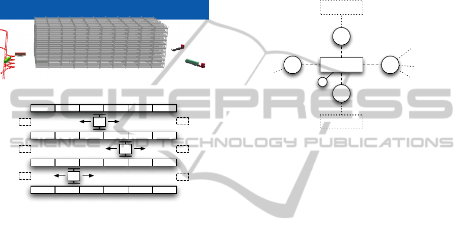
process with several locations. Figure 7 depicts a
model of a container rack storage with four racks,
three AS/RS and three load/unload areas on each side.
The whole model is described in (Asef-Vaziri and
Khoshnevis, 2000).
(a) The simulated rack storage.
A
0
A
1
A
2
(b) Diagram of the rack storage.
Figure 7: A rack storage for maritime containers. It consists
of four racks, three AS/RS and three load/unload areas on
each end (dotted rectangles).
The storage is used as a buffer in a maritime con-
tainer terminal. Container unloaded from a ship are
stored in the racks until trucks become available to
transport them inland. The same applies for the other
way round. In this scenario the AS/RS take contain-
ers from both ends and store them in one of the two
racks accessible to them. When a ship or truck ar-
rives specific containers are brought to the appropri-
ate load/unload stations. As depicted, each rack can
be accessed from both sides and therefore from two
AS/RS.
In a previous attempt standard components where
used to model the setup. A single AS/RS had to be
implemented as two different entities, one for each
reachable rack. Also, the racks had two rows instead
of one so that two AS/RS could not get into conflict
when accessing a storage place. This approach didn’t
match the originating setup (cp. Figure 7(a)) and fur-
thermore, the synchronization of the two entities rep-
resenting one AS/RS was very cumbersome and error-
prone. In the end we had to reprogram this storage
from scratch to make it functioning as intended.
However, with the architecture described in this
paper such a complex warehousing component can be
implemented much more easily. The most interesting
part in this implementation is the communication of
the AS/RS with each other to avoid conflicts in ac-
cessing the storage and load/unload areas. As we will
see, this communication can be done solely through
state changes on the locations. The initial setup for
A
1
is shown in Figure 8.
A
1
L
R
3
R
2
L
r
L
l
A
0
A
2
Figure 8: The setup for AS/RS A
1
. It is connected to five lo-
cations: Two racks (R
2
, R
3
) and two load/unload areas (L
l
,
L
r
) and a location to store the currently carried container
(L).
The AS/RS itself has one location L where it
stores the one container that it currently carries. Fur-
thermore, it has access to the two load and unload
areas at both sides, depicted as L
l
and L
r
. And, of
course, it can access the two racks R
2
and R
3
- as the
other two AS/RS can (also shown in the figure).
5.2.1 Handling the Load/unload-Areas
The load/unload-areas serve as gateways to the rest
of the model. At any point in time trucks can arrive,
blocking the areas until they have been served by the
AS/RS. However, due to simulation of a warehouse
with particular orders, a supervisor will deploy jobs
for the AS/RS as needed. Such a job contains specific
instructions how to handle a certain container or how
to serve a specific truck.
5.2.2 Accessing the Racks
The places within a rack can be accessed from
both sides and therefore by two independent AS/RS.
Therefore, a synchronization has to take place to
avoid conflicts during access. For example, each of
the two AS/RS might want to store a container in the
same place. This conflict can be resolved in several
ways: First of all, one can make the AS/RS more in-
telligent, allowing them to directly communicate with
each other. Due to the asynchronous setting such a
ImprovingFlow-BasedModelingofEnterpriseSystemsandModelingofCustomWarehouseSystemsind3fact
99

communication protocol can be come very complex
and hard to maintain. Another approach would be
to implement a supervisor for the warehouse system.
This leads to a very complex supervisor which has the
same drawbacks as the solution before.
Instead, in our implementation both AS/RS can
easily communicate through the states of the places.
The places can be seen as a resource that has to be
locked before it can be accessed. An AS/RS can indi-
cate the (future) usage of a particular place simply by
setting a place inaccessible. Either to store a container
(if it’s an empty place) or to handle the container that
is stored in that place.
The communication through the states of the
places within the locations has the advantage that no
explicit communication is required, that is is asyn-
chronously and that no external supervisor or conflict
solver is needed. This makes this approach simple,
clean and easy to understand and implement.
6 IMPLEMENTATION DETAILS
As mentioned earlier, we implemented our concept
into our research simulation platform d
3
fact. Here we
report on some interesting details of the implementa-
tion.
Let a location have n associated processes
p
0
, . . . , p
n
. Now an arbitrary process p
s
∈
{p
0
, . . . , p
n
} makes changes to the location. This cre-
ates an update u
s
containing all information about the
changes, i.e. added and removed entities, now acces-
sible or inaccessible places. Unfortunately u
s
starts an
update cascade. That means, another process p
k
re-
sponds with its own update u
k
to the update u
s
. Now
u
k
again causes another process p
r
to respond, and so
on. A trivial update mechanism would inform each
of the n processes of every update. This can lead to
an efficiency problem. For example one process oc-
casionally creates new entities while another process
destroys them to replace them with completely new
entities. Every associated process now gets both up-
dates, even if the entities created in the first place do
not last long or have been destroyed already. Carry-
ing out each update can lead to a huge overhead when
updates contain oppositional or obsolete information.
Also, processes would have to be capable of deter-
mining the obsolete information in the update or the
differences between the last known and the current
state of the location. This would make the implemen-
tation of new processes more difficult, especially for
new users.
Instead of informing all processes about all up-
dates, we accumulate updates. This reduces the times
a process is informed about updates to a minimum
and the updates do not contain stale information. The
update mechanism we came up with can be found in
Listing 1. It resides in the location implementation.
Changes made by a process to the location trigger the
UPDATE() method. Here the parameter p is the pro-
cess initiating the changes and u is the update initiated
by p.
#p i s t h e s o u r c e p r o c e s s and u t h e u p d a t e
UPDATE( p , u )
put ( u ) → s t a c k
5 # i n f o r m p r o c e s s e s i n f r o n t o f p ab o u t u
0 → i
peek ( s t a c k ) → u
w h i le ( P [ i ] 6= p )
{
10 u → in form ( P [ i ] )
i +1 → i
}
# do n o t i n f o r m p a b o u t u
15 i f ( | s t a c k | > 1 )
{
# merge u w i t h p r e v i o u s u p d a t e
p o l l ( s t a c k ) → v
p o l l ( s t a c k ) → w
20 put ( v ∩ w) → s t a c k
}
e l s e
{
# t h e r e i s o n l y on e u p d a t e l e f t on t h e s t a c k
25 i +1 → i
peek ( s t a c k ) → u
w h i le ( i < | P | )
{
u → info rm ( P [ i ] )
30 i +1 → i
}
p o l l ( s t a c k ) # c l e a r s t a c k
}
Listing 1: The Update-algorithm.
We inform the processes in the order they were
added. If one process happens to start a new update
during a running update we suspend the current up-
date and start from the beginning (with the new up-
date).
Figure 9 shows an exemplified update cascade.
Horizontal lines indicate which process is informed
about which update at which point in time. Horizon-
tally the processes p
0
, . . . , p
n
are shown. The time
line is displayed vertically. A back pointer indicates
the accumulation of two updates. Basically the pro-
cedure starts with an update u
s
. Now we consider
p
k
to be the next process responding to the changes
made by u
s
. That means, that u
s
is applied to all pro-
cesses before process p
k
. Upon informing p
k
about
SIMULTECH2013-3rdInternationalConferenceonSimulationandModelingMethodologies,Technologiesand
Applications
100

u
s
p
n
p
0
u
k
u
s+k
u
r
u
l
u
j
u
l+j
u
r+l+j
u
s+k+r+l+j
t
p
l
p
k
p
r
p
j
p
j
p
l
p
r
p
k
p
s
Figure 9: Generic example showing how our update method
works. Horizontally all processes are displayed while the
time line is plotted vertically.
u
s
it triggers a new update u
k
. As stated before we
now start from the beginning, informing all processes
before p
k
(cp. Listing 1, Lines 5-12). After doing so,
all processes p < p
k
are informed about the updates
u
s
and u
k
. Before informing the processes p > p
k
we
merge both updates into the new update u
s+k
elimi-
nating all oppositional information (Line 20, Listing
1). As depicted in Figure 9 this update algorithm can
also handle recursively triggered updates.
7 CONCLUSIONS
In this paper we report on a concept that enhances the
flow-based modeling found in current enterprise sim-
ulation software. The presented concept splits the cur-
rent building block design into a location where enti-
ties are stored and the building block behavior (pro-
cess). Through this separation an arbitrary number of
processes can be associated with a location, enabling
the combination of them. Another advantage is the
possibility to associate a process with a set of loca-
tions. This enables the easy implementation of man-
agement logic like those used in warehousing sys-
tems. Other advantages are the simple analysis of the
systems behavior and the code portability and flexibil-
ity. We showed that our location design covers a wide
range of storage types, like working places, trucks,
machines, shelfs, block storages, etc.
REFERENCES
Asef-Vaziri, A. and Khoshnevis, B. (2000). Performance
analysis of automated technology in maritime con-
tainer terminals. Progress in Material Handling Re-
search, pages 165–178.
Gregory, J. (2009). Game engine architecture. A K Peters,
first edition.
Incontrol Simulation Software (2009). Tutorial ed 8.
Incontrol Simulation Software (2012a). Enter-
prise dynamics. Accessed April, 2012. http://
www.incontrolsim.com.
Incontrol Simulation Software (2012b). Enterprise dy-
namics products. Accessed April, 2012. http://
www.incontrolsim.com/en/products.html.
Incontrol Simulation Software (2012c). Enterprise dynam-
ics technical overview. Accessed April, 2012. http://
www.incontrolsim.com/en/ed-platform/technical-
over view.html.
Muller, D. (1989). As/rs and warehouse modeling. In Pro-
ceedings of the 21st conference on Winter simulation,
pages 802–810. ACM.
Nygaard, K. and Dahl, O.-J. (1978). The development of
the simula languages. SIGPLAN Not., 13(8):245–272.
Renken, H., Fischer, M., and Laroque, C. (2011). An easy
extendable modeling framework for discrete event
simulation models and their visualization. In Proceed-
ings of The 25th European Simulation and Modelling
Conference - ESM’2011.
Rockwell Automation, Inc. (2011). Arena simulation soft-
ware by rockwell automation. Accessed Feb. 1, 2011.
http://www.arenasimulation.com/.
Siemens (2012). Simulation & testing. Accessed April,
2012. http://www.industry.siemens.com/industry
solutions/global/en/cross industry solutions/automat
ion it/simul test/Pages/Default.aspx.
St
˚
ahl, I. and AB, B. (2011). Webgpss - simula-
tion made simple. Accessed Feb. 1, 2011. http://
www.webgpss.com/.
Takakuwa, S. (1996). Efficient module-based modeling for
a large-scale as/rs-agv system. In Proceedings of the
28th conference on Winter simulation, pages 1141–
1148. IEEE Computer Society.
XJ Technologies Company (2012a). Discrete event simu-
lation modeling tool. Accessed April, 2012. http://
www.xjtek.com/anylogic/approaches/discreteevent/.
XJ Technologies Company (2012b). Why anylogic sim-
ulation software? Accessed April, 2012. http://
www.xjtek.com/anylogic/why anylogic/.
ImprovingFlow-BasedModelingofEnterpriseSystemsandModelingofCustomWarehouseSystemsind3fact
101
