
Watermarking Images in the Frequency Domain by Exploiting
Self-inverting Permutations
Maria Chroni, Angelos Fylakis and Stavros D. Nikolopoulos
Department of Computer Science, University of Ioannina, GR-45110 Ioannina, Greece
Keywords:
Watermarking Techniques, Image Watermarking Algorithms, Self-inverting Permutations, 2D Representa-
tions of Permutations, Encoding, Decoding, Frequency Domain, Experimental Evaluation.
Abstract:
In this work we propose efficient codec algorithms for watermarking images that are intended for uploading
on the web under intellectual property protection. Headed to this direction, we recently suggested a way in
which an integer number w which being transformed into a self-inverting permutation, can be represented in
a two dimensional (2D) object and thus, since images are 2D structures, we have proposed a watermarking
algorithm that embeds marks on them using the 2D representation of w in the spatial domain. Based on the
idea behind this technique, we now expand the usage of this concept by marking the image in the frequency
domain. In particular, we propose a watermarking technique that also uses the 2D representation of self-
inverting permutations and utilizes marking at specific areas thanks to partial modifications of the image’s
Discrete Fourier Transform (DFT). Those modifications are made on the magnitude of specific frequency
bands and they are the least possible additive information ensuring robustness and imperceptiveness. We
have experimentally evaluated our algorithms using various images of different characteristics under JPEG
compression. The experimental results show an improvement in comparison to the previously obtained results
and they also depict the validity of our proposed codec algorithms.
1 INTRODUCTION
Internet technology, in modern communities, be-
comes day by day an indispensable tool for everyday
life since most people use it on a regular basis and do
many daily activities online (Garfinkel, 2001). This
frequent use of the internet means that measures taken
for internet security are indispensable since the web is
not risk-free (Chun-Shien et al., 2000; Davis, 1997).
One of those risks is the fact that the web is an en-
vironment where intellectual property is under threat
since a huge amount of public personal data is contin-
uously transferred, and thus such data may end up on
a user who falsely claims ownership.
It is without any doubt that images, apart from
text, are the most frequent type of data that can be
found on the internet. As digital images are a char-
acteristic kind of intellectual material, people hesitate
to upload and transfer them via the internet because
of the ease of intercepting, copying and redistribut-
ing in their exact original form (O’Ruanaidh et al.,
1996). Encryption is not the problem’s solution in
most cases, as most people that upload images in a
website want them to be visible by everyone, but safe
and theft protected as well. Watermarks are a solu-
tion to this problem, since thanks to them someone
can claim the property of an image if he previously
inserted one in it. Image watermarks can be visible or
not, but if we don’t want any cosmetic changes in an
image then an invisible watermark should be used and
that’s what our work suggests, a technique according
to which invisible watermarks are embedded into im-
ages using features of the image’s frequency domain
and graph theory as well.
We next briefly describe the main idea behind the
watermarking technique, the motivation of our work,
and our contribution.
Watermarking. In general, watermarks are symbols
which are placed into physical objects such as docu-
ments, photos, etc. and their purpose is to carry infor-
mation about objects’ authenticity (Cox et al., 2008).
A digital watermark is a kind of marker embed-
ded in a digital object such as image, audio, video, or
software and, like a typical watermark, it is used to
identify ownership of the copyright of such an object.
Digital watermarking (or, hereafter, watermarking) is
a technique for protecting the intellectual property of
45
Chroni M., Fylakis A. and Nikolopoulos S..
Watermarking Images in the Frequency Domain by Exploiting Self-inverting Permutations.
DOI: 10.5220/0004371100450054
In Proceedings of the 9th International Conference on Web Information Systems and Technologies (WEBIST-2013), pages 45-54
ISBN: 978-989-8565-54-9
Copyright
c
2013 SCITEPRESS (Science and Technology Publications, Lda.)

a digital object; the idea is simple: a unique marker,
which is called watermark, is embedded into a digi-
tal object which may be used to verify its authenticity
or the identity of its owners (Grover, 1997; Collberg
and Nagra, 2010). More precisely, watermarking can
be described as the problem of embedding a water-
mark w into an object I and, thus, producing a new
object I
w
, such that w can be reliably located and ex-
tracted from I
w
even after I
w
has been subjected to
transformations (Collberg and Nagra, 2010); for ex-
ample, compression, scaling or rotation in case where
the object is an image.
In the image watermarking process the digital in-
formation, i.e., the watermark, is hidden in image
data. The watermark is embedded into image’s data
through the introduction of errors not detectable by
human perception (Cox et al., 1996); note that, if the
image is copied or transferred through the internet
then the watermark is also carried with the copy into
the image’s new location.
Motivation. Intellectual property protection is one of
the greatest concerns of internet users today. Digital
images are considered a representative part of such
properties so we consider important, the development
of methods that deter malicious users from claiming
others’ ownership, motivating internet users to feel
more safe to publish their work online.
Image Watermarking, is a technique that serves
the purpose of image intellectual property protection
ideally as in contrast with other techniques it allows
images to be available to third internet users but si-
multaneously carry an “identity” that is actually the
proof of ownership with them. This way image wa-
termarking achieves its target of deterring copy and
usage without permission of the owner. What is more
by saying watermarking we don’t necessarily mean
that we put a logo or a sign on the image as research
is also done towards watermarks that are both invisi-
ble and robust.
Our work suggests a method of embedding a nu-
merical watermark into the image’s structure in an
invisible and robust way to specific transformations,
such as JPEG compression.
Contribution. In this work we present an efficient
and easily implemented technique for watermarking
images that we are interested in uploading in the web
and making them public online; this way web users
are enabled to claim the ownership of their images.
What is important for our idea is the fact that it
suggests a way in which an integer number can be rep-
resented with a two dimensional representation (or,
for short, 2D representation). Thus, since images are
two dimensional objects that representation can be ef-
ficiently marked on them resulting the watermarked
images. In a similar way, such a 2D representation
can be extracted for a watermarked image and con-
verted back to the integer w.
Having designed an efficient method for encoding
integers as self-invertingpermutations, we propose an
efficient algorithm for encoding a self-inverting per-
mutation π
∗
into an image I by first mapping the el-
ements of π
∗
into an n
∗
× n
∗
matrix A
∗
and then us-
ing the information stored in A
∗
to mark specific ar-
eas of image I in the frequency domain resulting the
watermarked image I
w
. We also propose an efficient
algorithm for extracting the embedded self-inverting
permutation π
∗
from the watermarked image I
w
by lo-
cating the positions of the marks in I
w
; it enables us to
recontract the 2D representation of the self-inverting
permutation π
∗
.
It is worth noting that although digital watermark-
ing has made considerable progress and became a
popular technique for copyright protection of multi-
media information (Cox et al., 1996), our work pro-
poses something new. We first point out that our
watermarking method incorporates such properties
which allow us to successfully extract the watermark
w from the image I
w
even if the input image has been
compressed with a lossy method, scaled and/or ro-
tated. In addition, our embedding method can trans-
form a watermark from a numerical form into a two
dimensional (2D) representation and, since images
are 2D structures, it can efficiently embed the 2D
representation of the watermark by marking the high
frequency bands of specific areas of an image. The
key idea behind our extracting method is that it does
not actually extract the embedded information instead
it locates the marked areas reconstructing the water-
mark’s numerical value.
We have evaluated the embedding and extracting
algorithms by testing them on various and different
in characteristics images that were initially in JPEG
format and we had positive results as the watermark
was successfully extracted even if the image was con-
verted back into JPEG format with various compres-
sion ratios. What is more, the method is open to ex-
tensions as the same method might be used with a
different marking procedure such as the one we used
in our previous work. Note that, all the algorithms
have been developed and tested in MATLAB (Gonza-
lez et al., 2003).
2 THEORETICAL FRAMEWORK
In this section we first describe discrete structures,
namely, permutations and self-inverting permuta-
WEBIST2013-9thInternationalConferenceonWebInformationSystemsandTechnologies
46

tions, and briefly discuss a codec system which en-
codes an integer number w into a self-inverting per-
mutation π. Then, we present a transformation of a
watermark from a numerical form to a 2D form (i.e.,
2D representation) through the exploitation of self-
inverting permutation properties.
2.1 Self-inverting Permutations
Informally, a permutation of a set of objects S is an
arrangement of those objects into a particular order,
while in a formal (mathematical) way a permutation
of a set of objects S is defined as a bijection from S to
itself (i.e., a map S → S for which every element of S
occurs exactly once as image value).
Permutations may be represented in many ways.
The most straightforward is simply a rearrange-
ment of the elements of the set N
n
= {1, 2, . . . , n};
in this way we think of the permutation π =
(5, 6, 9, 8, 1, 2, 7, 4, 3) as a rearrangement of the ele-
ments of the set N
9
such that “1 goes to 5”, “2 goes to
6”, “3 goes to 9”, “4 goes to 8”, and so on (Sedgewick
and Flajolet, 1996; Golumbic, 1980). Hereafter, we
shall say that π is a permutation over the set N
9
.
Definition 2.1.1. Let π = (π
1
, π
2
, . . . , π
n
) be a permu-
tation over the set N
n
, where n > 1. The inverse of the
permutation π is the permutation q = (q
1
, q
2
, . . . , q
n
)
with q
π
i
= π
q
i
= i. A self-inverting permutation (or,
for short, SiP) is a permutation that is its own inverse:
π
π
i
= i.
By definition, a permutation is a SiP (self-
inverting permutation) if and only if all its cycles
are of length 1 or 2; for example, the permutation
π = (5, 6, 9, 8, 1, 2, 7, 4, 3) is a SiP with cycles: (1, 5),
(2, 6), (3, 9), (4, 8), and (7).
2.2 Encoding Numbers as SiPs
There are several systems that correspond integer
numbers into permutations or self-inverting permuta-
tion (Sedgewick and Flajolet, 1996). Recently, we
have proposed algorithms for such a system which
efficiently encodes an integer w into a self-inverting
permutations π and efficiently decodes it. The algo-
rithms of our codec system run in O(n) time, where n
is the length of the binary representation of the integer
w, while the key-idea behind its algorithms is mainly
based on mathematical objects, namely, bitonic per-
mutations (Chroni and Nikolopoulos, 2010).
2.3 2D Representations
We first define the two-dimensional representation
(2D representation) of a permutation π over the
set N
n
= {1, 2, . . . , n}, and then its 2DM representa-
tion which is more suitable for efficient use in our
codec system.
In the 2D representation, the elements of the per-
mutation π = (π
1
, π
2
, . . . , π
n
) are mapped in specific
cells of an n× n matrix A as follows:
number π
i
−→ entry A(π
−1
i
, π
i
)
or, equivalently, the cell at row i and column π
i
is la-
beled by the number π
i
, for each i = 1, 2, . . . , n.
Figure 1(a) shows the 2D representation of the self-
inverting permutation π = (6, 3, 2, 4, 5, 1).
Note that, there is one label in each row and in
each column, so each cell in the matrix A corresponds
to a unique pair of labels; see, (Sedgewick and Fla-
jolet, 1996) for a long bibliography on permutation
representations and also in (Chroni and Nikolopoulos,
2011) for a DAG representation.
Based on the previously defined 2D representa-
tion of a permutation π, we next propose a two-
dimensional marked representation (2DM representa-
tion) of π which is an efficient tool for watermarking
images.
In our 2DM representation, a permutation π over
the set N
n
= {1, 2, . . . , n} is represented by an n × n
matrix A
∗
as follows:
◦ the cell at row i and column π
i
is marked by a
specific symbol, for each i = 1, 2, . . . , n;
◦ in our implementation, the used symbol is the as-
terisk, i.e., the character “*”.
Figure 1(b) shows the 2DM representation of the per-
mutation π. It is easy to see that, since the 2DM repre-
sentation of π is constructed from the corresponding
2D representation, there is also one symbol in each
row and in each column of the matrix A
∗
.
We next present an algorithm which extracts the
permutation π from its 2DM representation matrix.
More precisely, let π be a permutation over N
n
and let
A
∗
be the 2DM representation matrix of π (see, Fig-
ure 1(b)); given the matrix A
∗
, we can easily extract π
from A
∗
in linear time (i.e., linear in the size of matrix
A
∗
) by the following algorithm:
Algorithm. Extract π from 2DM
Input: the 2DM representation matrix A
∗
of π;
Output: the permutation π;
1. For each row i of matrix A
∗
, 1 ≤ i ≤ n, and
for each column j of matrix A
∗
, 1 ≤ j ≤ n,
if the cell (i, j) is marked then π
i
← j;
WatermarkingImagesintheFrequencyDomainbyExploitingSelf-invertingPermutations
47

2
6
5
4
3
2
1
1
2
3 4
5
6
3
4
1
6
5
6
5
4
3
2
1
1
2
3 4
5
6
*
*
*
*
*
*
(a)
(b)
Figure 1: The 2D and 2DM representations of the self-
inverting permutation π = (6, 3, 2, 4, 5, 1).
2. Return the permutation π;
Remark 2.3.1. It is easy to see that the resulting per-
mutation π, after the execution of Step 1, can be taken
by reading the matrix A
∗
from top row to bottom
row and write down the positions of its marked cells.
Since the permutation π is a self-inverting permuta-
tion, its 2D matrix A has the following property:
◦ A(i, j) = j if π
i
= j, and
◦ A(i, j) = 0 otherwise, 1 ≤ i, j ≤ n.
Thus, the corresponding matrix A
∗
is symmetric:
◦ A
∗
(i, j) = A
∗
( j, i) = “mark” if π
i
= j, and
◦ A
∗
(i, j) = A
∗
( j, i) = 0 otherwise, 1 ≤ i, j ≤ n.
Based on this property, it is also easy to see that the
resulting permutation π can be also taken by reading
the matrix A
∗
from left column to right column and
write down the positions of its marked cells.
Hereafter, we shall denote by π
∗
a SiP and by n
∗
the number of elements of π
∗
.
2.4 The Discrete Fourier Transform
The Discrete Fourier Transform (DFT) is used to de-
compose an image into its sine and cosine compo-
nents. The output of the transformation represents
the image in the frequency domain, while the input
image is the spatial domain equivalent. In the image’s
fourier representation, each point represents a particu-
lar frequency contained in the image’s spatial domain.
If f(x, y) is an image of size N × M we use the
following formula for the Discrete Fourier Transform:
F(u,v) =
N−1
∑
x=0
M−1
∑
y=0
f(x, y)e
− j2π(
ux
N
+
vy
M
)
(1)
for values of the discrete variables u and v in the
ranges u = 0, 1, . . . , N − 1 and v = 0, 1, . . . , M − 1
In a similar manner, if we have the transform
F(u,v) i.e the image’s fourier representation we can
use the Inverse Fourier Transform to get back the im-
age f(x, y) using the following formula:
f(x, y) =
1
NM
N−1
∑
u=0
M−1
∑
v=0
F(u,v)e
j2π(
ux
N
+
vy
M
)
(2)
for x = 0, 1, . . . , N − 1 and y = 0, 1, . . . , M − 1
Typically, in our method, we are interested in
the magnitudes of DFT coefficients. The magnitude
|F(u,v)| of the Fourier transform at a point is how
much frequency content there is and is calculated by
Equation (1) (Gonzalez and Woods, 2007).
2.5 Previous Results
Recently, we proposed a watermarking technique
based on the idea of interfering with the image’s pixel
values in the spatial domain. In the following para-
graphs, we briefly describe the steps of this idea and
state main points regarding some of its advantages
and disadvantages. Recall that, in the current work
we suggest an expansion to this idea by moving from
the spatial domain to the image’s frequency domain.
The embedding algorithm first computes the 2DM
representation of the permutation π
∗
, that is, the n
∗
×
n
∗
array A
∗
(see, Subsection 2.3); the entry (i, π
∗
i
)
of the array A
∗
contains the symbol “*”, 1 ≤ i ≤ n
∗
.
Next, it takes the N × M sized input image I and cov-
ers it with an n
∗
× n
∗
imaginary grid C, resulting in
n
∗
× n
∗
grid-cells C
ij
, 1 ≤ i, j ≤ n
∗
. Then it goes to
each C
ij
and locates its central pixel p
0
ij
and the four
pixels p
1
ij
, p
2
ij
, p
3
ij
, and p
4
ij
around it, 1 ≤ i, j ≤ n
∗
(we shall call them cross pixels). It then computes the
difference between the value of the central pixel p
0
ij
and the average value of the twelve neighboring pix-
els storing it in the variable dif(p
0
ij
). Finally, it com-
putes the maximum absolute value of all n
∗
× n
∗
dif-
ferences dif(p
0
ij
), 1 ≤ i, j ≤ n
∗
, and stores it in the vari-
able Maxdif(I). Recall that the embedding algorithm
goes to each central pixel p
0
ij
of each grid-cell C
ij
,
1 ≤ i, j ≤ n
∗
, and if the corresponding entry A
∗
(i, j)
contains the symbol “*”, then it increases the value
of each one of previously described, cross pixels by
Maxdif(I) − dif(p
0
ij
) + c, where c is a positive num-
ber used to strengthen the marks.
In a similar manner, the extracting algorithm is
searching each line i of the imaginary grid C to find
among the n
∗
grid-cells C
i1
,C
i2
, . . . ,C
in
∗
the column
number j of the one that has the greatest difference
between the neighboring and cross pixels, 1 ≤ i, j ≤
n
∗
; then, the element π
∗
i
is set equal to j.
WEBIST2013-9thInternationalConferenceonWebInformationSystemsandTechnologies
48

Regarding the main points of the previous tech-
nique, we should first mention that for images with
general characteristics and relatively large size this
method delivers optically good results. By saying
“good results” we mean that the modifications made
are quite invisible. Also the method’s algorithms run
really fast as they simply access a finite number of
pixels. Furthermore, both the embedding and extract-
ing algorithms are easy to modify and adjust for vari-
ous scenarios.
On the other hand, the method fails to deliver good
results either for relatively small images or for im-
ages that depict something smooth which allows the
eye to distinct the modifications on the image. Also
we decided to move to a new method as there were
also problems due to the fact that the positions of the
crosses are centered at strictly specific positions caus-
ing difficulties in the extracting methods.
3 THE FREQUENCY DOMAIN
APPROACH
Having described an efficient method for encoding in-
tegers as self-inverting permutations using the 2DM
representation of self-inverting permutations, we next
describe codec algorithms that efficiently encode and
decode a watermark into the image’s frequency do-
main (Solachidis and Pitas, 2001; Licks and Hordan,
2000; Gonzalez and Woods, 2007).
3.1 Embed Watermark into Image
We next describe the embedding algorithm of our pro-
posed technique which encodes a self-inverting per-
mutation (SiP) π
∗
into a digital image I. Recall that,
the permutation π
∗
is obtained over the set N
n
∗
, where
n
∗
= 2n + 1 and n is the length of the binary repre-
sentation of an integer w which actually is the im-
age’s watermark (Chroni and Nikolopoulos, 2010);
see, Subsection 2.2.
The watermark w, or equivalently the self-
inverting permutation π
∗
, is invisible and it is inserted
in the frequency domain of specific areas of the im-
age I. More precisely, we mark the DFT’s magnitude
of an image’s area using two ellipsoidal annuli, de-
noted hereafter as “Red” and “Blue” (see, Figure 2).
The ellipsoidal annuli are specified by the following
parameters:
◦ P
r
, the width of the “Red” ellipsoidal annulus,
◦ P
b
, the width of the “Blue” ellipsoidal annulus,
◦ R
1
and R
2
, the radiuses of the “Red” ellipsoidal
annulus on y-axis and x-axis, respectively.
The algorithm takes as input a SiP π
∗
and an image I,
in which the user embeds the watermark, and returns
the watermarked image I
w
; it consists of the following
steps.
R2
R1
Pr
Pb
Figure 2: The “Red” and “Blue” ellipsoidal annuli.
Algorithm. Embed SiP-to-Image
Input: the watermark π
∗
≡ w and the host image I;
Output: the watermarked image I
w
;
Step 1. Compute first the 2DM representation of the
permutation π
∗
, i.e., construct an array A
∗
of size n
∗
×
n
∗
such that the entry A
∗
(i, π
∗
i
) contains the symbol
“*”, 1 ≤ i ≤ n
∗
.
Step 2. Next, compute the size of the input image I,
say, N × M, and cover the image I with an imaginary
grid C with n
∗
× n
∗
grid-cells C
ij
of size
N
n
∗
×
M
n
∗
,
1 ≤ i, j ≤ n
∗
.
Step 3. For each grid-cell C
ij
, compute the Dis-
crete Fourier Transform (DFT) using the Fast Fourier
Transform (FFT) algorithm, resulting in a n
∗
×n
∗
grid
of DFT cells F
ij
, 1 ≤ i, j ≤ n
∗
.
Step 4. For each DFT cell F
ij
, compute its magni-
tude M
ij
and phase P
ij
matrices which are both of size
N
n
∗
×
M
n
∗
, 1 ≤ i, j ≤ n
∗
.
Step 5. Then, the algorithm takes each of the n
∗
×
n
∗
magnitude matrices M
ij
, 1 ≤ i, j ≤ n
∗
, and places
two imaginary ellipsoidal annuli, denoted as “Red”
and “Blue”, in the matrix M
ij
(see, Figure 2). In our
implementation,
◦ the “Red” is the outer ellipsoidal annulus while
the “Blue” is the inner one. Both are concentric at
the center of the M
ij
magnitude matrix and have
widths P
r
and P
b
, respectively;
◦ the radiuses of the “Red” ellipsoidal annulus are
R
1
(y-axis) and R
2
(x-axis), while the “Blue” el-
lipsoidal annulus radiuses are computed in accor-
dance to the “Red” ellipsoidal annulus and have
values (R
1
− P
r
) and (R
2
− P
r
), respectively;
WatermarkingImagesintheFrequencyDomainbyExploitingSelf-invertingPermutations
49

◦ the inner perimeter of the “Red” ellipsoidal annu-
lus coincides to the outer perimeter of the “Blue”
ellipsoidal annulus;
◦ the values of the widths of the two ellipsoidal an-
nuli are P
r
= 2 and P
b
= 2, while the values of
their radiuses are R
1
=
N
2n
∗
and R
2
=
M
2n
∗
.
The areas covered by the “Red” and the “Blue” el-
lipsoidal annuli determine two groups of magnitude
values on M
ij
(see, Figure 2).
Step 6. For each magnitude matrix M
ij
, 1 ≤ i, j ≤ n
∗
,
compute the average of the values that are in the areas
covered by the “Red” and the “Blue” ellipsoidal an-
nuli; let AvgR
ij
be the average of the magnitude values
belonging to the “Red” ellipsoidal annulus and AvgB
ij
be the one of the “Blue” ellipsoidal annulus.
Step 7. For each magnitude matrix M
ij
, 1 ≤ i, j ≤ n
∗
,
compute first the variable D
ij
as follows:
◦ D
ij
= |AvgB
ij
− AvgR
ij
|, if AvgB
ij
≤ AvgR
ij
◦ D
ij
= 0, otherwise.
Then, for each row i of the magnitude matrix M
ij
,
1 ≤ i, j ≤ n
∗
, compute the maximum value of the vari-
ables D
i1
, D
i2
, . . . , D
in
∗
in row i; let MaxD
i
be the max
value.
Step 8. For each cell (i, j) of the 2DM representation
matrix A
∗
of the permutation π
∗
such that A
∗
ij
= “ ∗ ”
(i.e., marked cell), mark the corresponding grid-cell
C
ij
, 1 ≤ i, j ≤ n
∗
; the marking is performed by in-
creasing all the values in magnitude matrix M
ij
cov-
ered by the “Red” ellipsoidal annulus by the value
AvgB
ij
− AvgR
ij
+ MaxD
i
+ c, (3)
where c = c
opt
. The additive value of c
opt
is calcu-
lated by the function f (see, Subsection 3.3) which
returns the minimum possible value of c that enables
successful extracting.
Step 9. Reconstruct the DFT of the corresponding
modified magnitude matrices M
ij
, using the trigono-
metric form formula (Gonzalez and Woods, 2007),
and then perform the Inverse Fast Fourier Transform
(IFFT) for each marked cellC
ij
, 1 ≤ i, j ≤ n
∗
, in order
to obtain the image I
w
.
Step 10. Return the watermarked image I
w
.
In Figure 3 we demonstrate the main operations per-
formed by our embedding algorithm. In particular, we
show the marking process of the grid-cell C
44
of the
Lena image; in this example, we embed in the Lena
image the watermark number w which corresponds to
SiP (6, 3, 2, 4, 5, 1).
Input Image:
Watermark: (6, 3, 2, 4, 5, 1)
DFT
MAGNITUDE
PHASE
FFT
DFT
Watermarked Image:
IFFT
FFT
MARK
obtained for
each color of
the RGB model
w
I
I
Figure 3: The embedding process.
3.2 Extract Watermark from Image
In this section we describe the decoding algorithm of
our proposedtechnique. The algorithmextracts a self-
inverting permutation (SiP) π
∗
from a watermarked
digital image I
w
, which can be later represented as an
integer w.
The self-invertingpermutation π
∗
is obtained from
the frequency domain of specific areas of the water-
marked image I
w
. More precisely, using the same two
“Red” and “Blue” ellipsoidal annuli, we detect certain
areas of the watermarked image I
w
that are marked by
our embedding algorithm and these marked areas en-
able us to obtain the 2D representation of the permu-
tation π
∗
. The extracting algorithm works as follows:
Algorithm. Extract SiP-from-Image
Input: the watermarked image I
w
marked with π
∗
;
Output: the watermark π
∗
= w;
Step 1. Take the input watermarked image I
w
and
compute its N × M size. Then, cover I
w
with the
same imaginary grid C, as described in the embed-
ding method, having n
∗
× n
∗
grid-cells C
ij
of size
WEBIST2013-9thInternationalConferenceonWebInformationSystemsandTechnologies
50

N
n
∗
×
M
n
∗
.
Step 2. Then, again for each grid-cell C
ij
, 1 ≤ i, j ≤
n
∗
, using the Fast Fourier Transform (FFT) get the
Discrete Fourier Transform (DFT) resulting a n
∗
× n
∗
grid of DFT cells.
Step 3. For each DFT cell, compute its magnitude
matrix M
ij
and phase matrix P
ij
which are both of
size
N
n
∗
×
M
n
∗
.
Step 4. For each magnitude matrix M
ij
, place the
same imaginary “Red” and “Blue” ellipsoidal annuli,
as described in the embedding method, and compute
as before the average values that coincide in the area
covered by the “Red” and the “Blue” ellipsoidal an-
nuli; let AvgR
ij
and AvgB
ij
be these values.
Step 5. For each row i of C
ij
, 1 ≤ i ≤ n
∗
, search for
the j
th
column where AvgB
ij
− AvgR
ij
is minimized
and set π
∗
i
= j, 1 ≤ j ≤ n
∗
.
Step 6. Return the self-inverting permutation π
∗
.
Having presented the embedding and extracting algo-
rithms, let us next describe the function f which re-
turns the additive value c = c
opt
(see, Step 8 of the
embedding algorithm).
3.3 Function f
Based on our marking model, the embedding algo-
rithm amplifies the marks in the “Red” ellipsoidal an-
nulus by adding the output of the function f. What
exactly f does is returning the optimal value that al-
lows the extracting algorithm under the current re-
quirements, such as JPEG compression, to still be
able to extract the watermark from the image.
The function f takes as an input the characteristics
of the image and the parameters R
1
, R
2
, P
b
, and P
r
of
our proposed mark model (see, Step 5 of embedding
algorithm and Figure 2), and returns the minimum
possible c
opt
that added as c to the values of the “Red”
ellipsoidal annulus enables extracting (see, Step 8 of
the embedding algorithm). More precisely, the func-
tion f initially takes the interval [0, c
max
], where c
max
is a relatively great value such that if c
max
is taken as
c for marking the “Red” ellipsoidal annulus it allows
extracting, and computes the c
opt
in [0, c
max
].
Note that, c
max
allows extracting but because of
being great damages the quality of the image (see,
Figure 4). We mentioned relatively great because it
depends on the characteristics of each image. For a
specific image it is useless to use a c
max
greater than a
specific value, we only need a value that definitely en-
ables the extracting algorithm to successfully extract
the watermark.
We next describe the computation of the value c
opt
returned by the function f; note that, the parameters
P
b
and P
r
of our implementation are fixed with the
values 2 and 2, respectively. The main steps of this
computation are the following:
(i) Check if the extracting algorithm for c = 0 validly
obtains the watermark π
∗
= w from the image I
w
;
if yes, then the function f returns c
opt
= 0;
(ii) If not, that means, c = 0 doesn’t allow extracting;
then, the function f uses binary search on [0, c
max
]
and computes the interval [c
1
, c
2
] such that:
◦ c = c
1
doesn’t allow extracting,
◦ c = c
2
do allow extracting, and
◦ |c
1
− c
2
| < 0.2;
(iii) The function f returns c
opt
= c
2
;
As mentioned before, the function f returns the opti-
mal value c
opt
. Recall that, optimal means that it is
the smallest possible value which enables extracting
π
∗
= w from the image I
w
. It is important to be the
smallest one as that minimizes the additive informa-
tion to the image and, thus, assures minimum drop to
the image quality.
4 EXPERIMENTAL RESULTS
In this section we present the experimental re-
sults of the proposed watermarking codec algo-
rithms which we have implemented using the general-
purpose mathematical software package Matlab (ver-
sion 7.7.0) (Gonzalez et al., 2003). We tested our
codec algorithms on various 24-bit digital color im-
ages of various sizes (from 200× 130 up to 4600×
3700) and quality characteristics. Many of the images
in our image repository where taken from a web im-
age gallery (Petitcolas, 2012) and enriched by some
other images different in characteristics.
There are three main requirements of digital wa-
termarking: fidelity, robustness, and capacity (Cox
et al., 2008). Our watermarking method appears to
have high fidelity and robustness against JPEG com-
pression.
Initially, we had to choose the appropriate values
for the parameters of the quality function f. In our
implementation we set both of the parameters P
r
and
P
b
equal to 2 (see, Section 3.1). Recall that, the value
2 is a relatively small value which allows us to mod-
ify a satisfactory number of pixels in order to embed
the watermark and successfully extract it, without af-
fecting images’ quality. Note that, for great in size
images, a smaller width reduces the strength of the
WatermarkingImagesintheFrequencyDomainbyExploitingSelf-invertingPermutations
51

watermark. There isn’t a distance between the two el-
lipsoidal annuli as that enables the algorithm to apply
a small additiveinformation to the values of the “Red”
annulus. The two ellipsoidal annuli are inscribed to
the rectangle magnitude matrix, as we want to mark
images’ cells on the high frequency bands.
We mark the high frequencies by increasing their
values using mainly the additive parameter c = c
opt
because alterations in the high frequencies are less
detectable by human eye (Kaur et al., 2012). What
is more, in high frequencies most images contain less
information.
In this work we used JPEG images due to their
great importance on the web, since they are small
in size, while storing full color information (24
bit/pixel), and can be easily and efficiently transmit-
ted. Moreover, robustness to lossy compression is
an important issue when dealing with image authen-
tication. It should be observed that the design goal
of lossy compression systems is opposed to that of
watermark embedding systems. The Human Visual
System model of the compression system attempts to
identify and discard perceptually insignificant infor-
mation of the image, whereas the goal of the water-
marking system is to embed the watermark informa-
tion without altering the visual perception of the im-
age (Zain, 2011).
The quality factor (or, for short, Q-factor) is a
number that determines the degree of loss in the com-
pression process when saving an image. In general,
JPEG recommends a quality factor of 75–95 for visu-
ally indistinguishable quality difference, and a qual-
ity factor of 50–75 for merely acceptable quality. We
compressed the images with Matlab JPEG compres-
sor from
imwrite
with different quality factors; we
present results for Q = 85, Q = 75 and Q = 65.
The quality function f returns the factor c, which
has the minimum value c
opt
that allows the extract-
ing algorithm to successfully extract the watermark.
In fact, this value c
opt
(see, Formula 3) is the main
additive information embedded into the image. De-
pending on the images and the amount of compres-
sion, we need to increase the watermark strength by
increasing the factor c. The value of c increases as
the quality factor of JPEG compression decreases. It
is obvious that the embedding algorithm is image de-
pendent. It is worth noting that, the c
opt
values are
small for images of relatively small size while these
values increase as we move to images of greater size.
To demonstrate the differences on watermarked
image quality, with respect to the values of the ad-
ditive factor c, we watermarked the original image
lena.jpg and we embedded a watermark with c = c
max
and c = c
opt
, where c
max
>> c
opt
(see, Figure 4);
Figure 4: The original image of Lena and its two water-
marked images with c = c
max
and c = c
opt
; the watermark
corresponds to SiP (6,3,2,4,5,1).
in the watermarked image in the middle we used
c = c
max
for illustrative purposes.
In order to evaluate the watermarked image qual-
ity obtained from our proposed watermarking method
we used two objective image quality assessment met-
rics, the Peak Signal to Noise Ratio (PSNR) and the
Structural Similarity Index Metric (SSIM). Our aim
was to prove that the watermarked image is closely
related to the original (image fidelity), because wa-
termarking should not introduce visible distortions in
the original image as that would reduce images’ com-
mercial value.
The PSNR metric is the ratio between the refer-
ence signal and the distortion signal, i.e., watermark,
in an image given in decibels (dB). It is well known
that, PSNR is most commonly used as a measure of
quality of reconstruction of lossy compression codecs
(e.g., for image compression). The higher the PSNR
value the closer the distorted image is to the original
or the better the watermark conceals. It is a popular
metric due to its simplicity, although it is well known
that this distortion metric is not absolutely correlated
with human vision.
For an initial image I of size N × M and its water-
marked image I
w
, PSNR is defined by the formula:
PSNR(I, I
w
) = 10log
10
N
2
max
MSE
, (4)
where N
max
is the maximum signal value that exists in
the original image and MSE is the Mean Square Error
which is represented by the formula as follows:
MSE(I, I
w
) =
1
N × M
N−1
∑
i=0
M−1
∑
j=0
(I(i, j) − I
w
(i, j))
2
. (5)
The SSIM image quality metric, developed by (Wang
et al., 2004), is considered to be correlated with the
quality perception of the HVS (Hore and Ziou, 2010).
The SSIM metric is defined as:
(6)
SSIM(I, I
w
) =
(2µµ
w
+C
1
)(2σ(I, I
w
) +C
2
)
(µ
2
+ µ
2
w
+C
1
)(σ(I)
2
+ σ(I
w
)
2
+C
2
)
,
WEBIST2013-9thInternationalConferenceonWebInformationSystemsandTechnologies
52
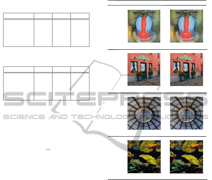
Table 1: The PSNR values of the original and watermarked
images, for compression of qualities Q = 85, 75 and 65.
Filename Q = 85 Q = 75 Q = 65
lena.jpg 54.0 50.0 46.8
baboon.jpg 49.3 46.2 42.5
trattoria.jpg 67.8 60.6 53.5
dome.jpg 64.6 59.8 54.9
aquarium.jpg 65.2 61.2 58.3
Table 2: The SSIM values of the original and watermarked
images, for compression of qualities Q = 85, 75 and 65.
Filename Q = 85 Q = 75 Q = 65
lena.jpg 0.997 0.993 0.986
baboon.jpg 0.995 0.989 0.980
trattoria.jpg 0.999 0.999 0.996
dome.jpg 0.999 0.999 0.997
aquarium.jpg 0.999 0.999 0.998
where µ and µ
w
are the mean luminances of the origi-
nal and watermarked image I respectively, σ(I) is the
standard deviation of I, σ(I
w
) is the standard devia-
tion of I
w
, whereas C
1
and C
2
are constants to avoid
null denominator. We use a mean SSIM (MSSIM) in-
dex to evaluate the overall image quality over the M
sliding windows,
MSSIM(I, I
w
) =
1
M
M
∑
i=0
SSIM(I, I
w
). (7)
The highest value of SSIM is 1, and it is achieved
when the original and watermarked images (I, I
w
re-
spectively) are identical.
Our watermarked images have excellent PSNR
and SSIM values. In Figure 5 we present four im-
ages of different sizes, along with their correspond-
ing PSNR and SSIM values. Typical values for the
PSNR in lossy image compression are between 40
and 70 dB, where higher is better. In our experiments,
the PSNR values of 90% of the watermarked images
were greater than 40 dB. The SSIM values are almost
equal to 1, which means that the watermarked image
is quite similar to the original one, which explains the
method’s high fidelity.
In Table 1 and 2 we demonstrate the PSNR and
SSIM values of some images that are used in this
work. These values are decreasing on smaller quality
factors. Also, as the additive value c = c
opt
increases
for each quality factor, the quality decreases. More-
over, the additive value c that embedsrobust marks for
qualities Q = 85, Q = 75 and Q = 65, does not result
in a significant image distortion as the tables suggest.
Original
Watermarked
500 x 500
PSNR = 60.6
c = 1.0
1024 x 1024
PSNR = 61.2
c = 3.1
PSNR = 46.2
200 x 200
Size / Name
c = 2.3
PSNR = 59.8
800 x 800
baboon.jpg
trattoria.jpg
dome.jpg
aquarium.jpg
c = 1.5
opt
opt
opt
opt
SSIM = 0.989
SSIM = 0.999
SSIM = 0.999
SSIM = 0.999
Figure 5: Some original images and their corresponding wa-
termarked ones; for each image, its size and its c
opt
, and
PSNR and SSIM values are also shown, for Q=75.
5 CONCLUDING REMARKS
In this paper we propose a method for embedding in-
visible watermarks into images and their intention is
to prove the authenticity of an image.
We experimentally tested our embedding and ex-
tracting algorithms on color JPEG images with var-
ious and different characteristics; our testing proce-
dure includes the phases of embedding a numerical
watermark w = π
∗
into a colored JPEG image I, stor-
ing the watermarked image I
w
in JPEG format with
various compression ratios, and extracting the water-
mark w = π
∗
from the image I
w
; in our method, the
watermark w is a self-inverting permutation π
∗
over
the set N
n
.
WatermarkingImagesintheFrequencyDomainbyExploitingSelf-invertingPermutations
53

We obtained positive results as the watermarks
were invisible, they didn’t affect the images’ qual-
ity and they were extractable despite the JPEG com-
pression. In addition, the experimental results show
an improvement in comparison to the previously ob-
tained results and they also depict the validity of our
proposed codec algorithms.
It is worth noting that the proposed algorithms are
robust against cropping or rotation attacks since the
watermarks are in SiP form, meaning that they deter-
mine the embedding positions in specific image ar-
eas, and thus if a part is being cropped or the image
is rotated, SiP’s symmetry property may allow us to
reconstruct the watermark. Furthermore, our codec
algorithms can also be modified in the future to get ro-
bust against scaling attacks. That can be achieved by
selecting multiple widths concerning the ellipsoidal
annuli depending on the size of the input image.
Finally, we should point out that the study of our
quality function f remains an open problem; indeed,
f could incorporate learning algorithms (Russell and
Norvig, 2010) so that to be able to return the c
opt
ac-
curately and in a very short computational time.
REFERENCES
Chroni, M. and Nikolopoulos, S. (2010). Encoding water-
mark integers as self-inverting permutations. In Proc.
Int’l Conference on Computer Systems and Tech-
nologies (CompSysTech’10), volume ACM ICPS 471,
pages 125 – 130.
Chroni, M. and Nikolopoulos, S. (2011). An efficient graph
codec system for software watermarking. In IEEE
Proc. 36th Int’l Conference on Computers, Software,
and Applications (STPSA’12), pages 595 – 600.
Chun-Shien, L., Shih-Kun, H., Chwen-Jye, S., and Hong-
Yuan, M. L. (2000). Cocktail watermarking for digital
image protection. IEEE Transactions on Multimedia,
2(4):209 – 224.
Collberg, C. and Nagra, J. (2010). Surreptitious Software.
Addison-Wesley.
Cox, I., Kilian, J., Leighton, T., and Shamoon, T. (1996). A
secure, robust watermark for multimedia. In Proc. 1st
Int’l Workshop on Information Hiding, volume LNCS
1174, pages 317 – 333.
Cox, I. J., Miller, M. L., Bloom, J. A., Fridrich, J.,
and Kalker, T. (2008). Digital Watermarking and
Steganography. Morgan Kaufmann, 2nd edition.
Davis, J. C. (1997). Intellectual property in cyberspace -
what technological / legislative tools are necessary for
building a sturdy global information infrastructure? In
IEEE Proc. Int’l Symposium on Technology and Soci-
ety, pages 66 – 74.
Garfinkel, S. (2001). Web Security, Privacy and Commerce.
O’Reilly, 2nd edition.
Golumbic, M. (1980). Algorithmic Graph Theory and Per-
fect Graphs. Academic Press, Inc., New York.
Gonzalez, R. C. and Woods, R. E. (2007). Digital Image
Processing. Prentice-Hall, 3rd edition.
Gonzalez, R. C., Woods, R. E., and Eddins, S. L. (2003).
Digital Image Processing using Matlab. Prentice-
Hall.
Grover, D. (1997). The Protection of Computer Software -
Its Technology and Applications. Cambridge Univer-
sity Press, New York.
Hore, A. and Ziou, D. (2010). Image quality metrics: Psnr
vs. ssim. Proc. 20th International conference on pat-
tern recognition, pages 2366 – 2369.
Kaur, M., Jindal, S., and Behal, S. (2012). A study of digi-
tal image watermarking. Journal of Research in Engi-
neering and Applied Sciences, 2:126 – 136.
Licks, V. and Hordan, R. (2000). On digital image wa-
termarking robust to geometric transformations. In
IEEE Proc. Int’l Conference on Image Processing,
volume 3, pages 690 – 693.
O’Ruanaidh, J. J. K., Dowling, W. J., and Boland, F. M.
(1996). Watermarking digital images for copyright
protection. Vision, Image and Signal Processing, IEE
Proceedings, 143(4):250 – 256.
Petitcolas, F. (2012). Image Database for Wa-
termarking. Retrieved September, 2012, from
http://www.petitcolas.net/fabien/watermarking/.
Russell, S. and Norvig, P. (2010). Artificial Intelligence: A
Modern Approach. Prentice-Hall, 3rd edition.
Sedgewick, R. and Flajolet, P. (1996). An Introduction to
the Analysis of Algorithms. Addison-Wesley.
Solachidis, V. and Pitas, I. (2001). Circularly symmetric
watermark embedding in 2-d dft domain. IEEE Trans-
actions on Image Processing, 10(11):1741 – 1753.
Wang, Z., Bovic, A., Sheikh, H., and Simoncelli, E. (2004).
Image quaity assessment: from error visibility to
structural similarity. IEEE Transactions on Image
Processing, 13(4):600 – 612.
Zain, J. M. (2011). Strict authentication watermark-
ing with jpeg compression (saw-jpeg) for medical
images. European Journal of Scientific Research,
abs/1101.5188:250 – 256.
WEBIST2013-9thInternationalConferenceonWebInformationSystemsandTechnologies
54
