
Shape from Multi-view Images based on Image Generation Consistency
Kosuke Wakabayashi, Norio Tagawa and Kan Okubo
Graduate School of System Design, Tokyo Metropolitan University, Hino-shi, Tokyo, Japan
Keywords:
Image Generation Consistency, Unification of Shape from X, Shape from Multi-view Images.
Abstract:
There are various and a lot of depth recovery methods have been studied, but a discussion about an unification
of individual methods is expected not to be enough yet. In this study, we argue that the importance and the
necessity of an image generation consistency. Various clues including binocular disparity, motion parallax,
texture, shading and so on can be effectively used for depth recovery for the case where each or some of
those are completely performed. However, in general, those clues without shading cause ideal and simplified
constraints, and for several cases those clues without shading are suitable for obtaining initial depth values for
the unification algorithm based on an image generation consistency. On the other hand, shading indicates a
strict characteristics for image generation and should be used for the key principle for the unification. Based on
the above strategy, as a first step of our scheme, through a simple problem with two-views, the unification of
binocular disparity and shading without explicit disparity detection is examined based on an image generation
consistency, and simple evaluation results are shown by simulations.
1 INTRODUCTION
There are various clues for depth recovery, for exam-
ple, stereo, motion, texture, blur and shading, and us-
ing each clue, a lot of methods have been proposed for
recovering a three dimensional (3-D) shape from im-
ages. For each clue, there is a condition under which
depth recovery is theoretically impossible, and Pog-
gio (Poggio et al., 1988) asserted the unification of
various modules, each of which recovers depth based
on a specific clue respectively, using an edge map
computed by preprocessing. Namely, multiple depth
maps obtained by all modules are incorporated into a
final result of a depth map. This strategy is effective
for the case where whole region can be partitioned so
that in the local regions the suitable clue for accurate
depth recovery exists respectively. However, in gen-
eral, there are the regions where an accurate depth can
not be recovered by a single certain clue and hence, a
superior unification of clues is required.
Most clues except shading are the constraints be-
tween specific features detected from images and
depth. These constraints can be used simply and ef-
ficiently for depth recovery, but sometimes the con-
straints are required to be improved by complicated
ways. For example, a simple binocular disparity con-
straint is inadequate for occlusions and intensity in-
consistency of a corresponding image pair caused by
a difference of appearance from two views includ-
ing a specular reflectance, and various studies have
been carried out (Lazaros et al., 2008). On the other
hand, shading constraint essentially depends on com-
plete image information instead of specific image fea-
tures, and hence, in addition to the depth, other 3-
D quantities including albedo should be also consid-
ered, although general shape from shading algorithm
assumes that albedo multiplied by an intensity of a
light source is known. From the above discussion, the
shading clue is fundamental and exact as compared
with the other clues, and it should be applied to depth
recovery in distinction from the other clues. The
similar concept has been argued (Hayakawa et al.,
1994), but in this research especially the unification of
shading and edge information was discussed and the
computational scheme to reduce computation costs is
mainly examined. In the following, we call the con-
straints except shading ”feature-based clues.” As de-
scribed above, since the shading constraint has many
quantities to be determined as a 3-D recovery, the
shading constraint for multi-view images becomes
important. Therefore, the shading clue with respect to
various 3-D quantities with multi-view images should
be called ”image generation consistency” preferably.
We propose a strategy, in which the feature-
based clues and the image generation consistency are
adopted hierarchically. At first, various feature-based
clues are applied to the pixels or the regions where
these clues are effective respectively, and all results
334
Wakabayashi K., Tagawa N. and Okubo K..
Shape from Multi-view Images based on Image Generation Consistency.
DOI: 10.5220/0004345203340340
In Proceedings of the International Conference on Computer Vision Theory and Applications (VISAPP-2013), pages 334-340
ISBN: 978-989-8565-48-8
Copyright
c
2013 SCITEPRESS (Science and Technology Publications, Lda.)

are unified so as to obtain a partial or sparse depth
map. Subsequently, using it as an initial value the
image generation consistency is imposed on all infor-
mation of observed multiple images to obtain a whole
depth map and other 3-D quantities accurately.
In this study, as a first step of our research, we
take up a simple problem, ”shape from two-view im-
ages,”and confirm the effectiveness of the image gen-
eration consistency. We suppose that initial values
of 3-D quantities including a depth map are obtained
by various feature-based clues, and in the numerical
evaluation below, good initial values are given heuris-
tically and are used. In future, we are going to de-
velop the system in which various feature-based clues
for obtaining rough and sparse 3-D quantities are ac-
tually used and the unification schemeproposed in this
study is effectively performed.
The intensity of images used in the numerical
evaluation consists of a diffuse reflectance and a spec-
ular reflectance. The strength of a diffuse reflectance
and a specular reflectance are unknown relative to
the strength of a parallel light source, but those are
constant on an object. Therefore, we recover both
strength using the length of a light source as a unit.
The direction of a light source is also unknownand re-
covered. We recover a depth and the other 3-D quan-
tities by the image generation consistency with two
images. The degree of the unknownvariables is larger
than the number of observations of one image, i.e. a
pixel number, hence it is worried that a unique solu-
tion cannot be determined by an usual shading analy-
sis using only one image. For the case where only the
diffuse reflectance exists, it was clarified that a two-
way ambiguity appears (Brooks and Horn, 1985). Ad-
ditionally, since there is no clear texture, an accurate
binocular disparity detection is difficult. Namely, our
strategy is expected to be needed to solve this problem
accurately in spite of the simpleness of this problem.
The above simple algorithm evaluated in this
study as a first step can be also regarded as a new
unification method of the binocular disparity and the
shading constraints. The most unification methods
proposed recently adopt almost the same strategy that
a stereo constraint is firstly used for specific image re-
gions or points where disparity detection can be easily
done to recover sparse depth map, and then a shading
constraint is used for the other region where the shad-
ing constraint can be used suitably (Samaras et al.,
2000). On the other hand, our algorithm does not
use the binocular disparity constraint directly and the
image generation consistency of two images is con-
cerned to at most, although a disparity detection re-
sult can be used as an initial value. As the similar
awareness of the issues, (Maki et al., 2002) proposed
a method based on the principle of the photometric
stereo using known object motion, but in which only
a shading and a motion are focused and a texture is
not considered essentially. As against this, our strat-
egy can deal with the distribution of albedo in princi-
ple, although, in this study, albedo is assumed to be
constant.
2 SHADING CONSISTENCY FOR
TWO-VIEWS
2.1 Formulation of Depth from Shading
Various shape from shading method have been exam-
ined (Zhang et al., 1999),(Szeliski, 1991), and almost
are based on the image irradiance equation:
I(x,y) = R(~n(x,y)), (1)
which represents that image intensity I at a image
point (x,y) is formulated as a function R of a surface
normal~n at the point (X,Y,Z) on a surface projecting
to (x,y) in the image. General R contains other vari-
ables such as a view direction, a light source direction
and albedo. These variables have to be determined in
advance or simultaneously with the shape from im-
ages in general.
From the image irradiance equation, image inten-
sity is uniquely determined by surface orientation not
by surface depth. Most formulations of shape from
shading problem have focused on determining surface
orientation using the parameters (p,q) representing
(Z
X
,Z
Y
), which is the first derivative of Z with respect
to X and Y. Hence, we can express the shape from
shading problem as solving for p(x,y) and q(x, y),
with which the irradiance equation holds, by minimiz-
ing the following objective function.
J ≡
Z
{I(x, y) − R(p(x,y),q(x,y))}
2
dxdy, (2)
where I(x, y) is an observed image intensity. How-
ever, this problem is highly under-constrained, and
additional constraints are required to determine a par-
ticular solution, for example a smoothness constraint.
Additionally, the solutions p(x,y) and q(x, y) will not
correspond to orientations of a continuous and dif-
ferential surface Z(x,y) in general. Therefore, the
post processing is required, which generates a surface
approximately satisfying the constraint p
Y
= q
X
, or
(Horn, 1990) proposed the objective function includ-
ing such a constraint implicitly.
To avoid these difficulties, we can represent
p(x,y) and q(x,y) as a first derivative of Z(x,y) ex-
plicitly and consider R(p,q) as a function of Z(x,y).
ShapefromMulti-viewImagesbasedonImageGenerationConsistency
335
In addition, using the second derivatives Z
XX
= p
X
and Z
YY
= q
Y
, Leclerc and Bobick (Leclerc and Bo-
bick, 1991) proposed the following objective function
for parallel projection,
J
LB
≡ (1 − λ)
Z
{I(x, y) − R(Z
X
(x,y),Z
Y
(x,y))}
2
dxdy
+λ
Z
Z
2
XX
(x,y) + Z
2
YY
(x,y)
dxdy, (3)
and minimized it with a discrete representation of
Z(x, y) and its derivatives. The method in (Leclerc
and Bobick, 1991) assumed only the Lambertian re-
flection as R(Z
X
,Z
Y
). In the objective function, λ in-
dicates a degree of smoothness required for Z(x,y),
and is initially set as 1 and is gradually decreased to
near zero with a hierarchical coarse to fine technique
using the multi-resolution image decomposition (Ter-
zopoulos, 1983).
In (Leclerc and Bobick, 1991), since parallel pro-
jection is adopted, we can use the relations Z
X
=
∂Z/∂x and Z
Y
= ∂Z/∂y. However, when we as-
sume perspective projection, the relations x = X/Z
and y = Y/Z have to be considered, and hence, the
following formulations are required to be used (Wak-
abayashi et al., 2012).
∂Z
∂X
=
1
Z
∂Z
∂x
,
∂Z
∂Y
=
1
Z
∂Z
∂y
, (4)
∂
2
Z
∂X
2
=
1
Z
2
∂
2
Z
∂x
2
−
1
Z
3
∂Z
∂x
2
, (5)
∂
2
Z
∂Y
2
=
1
Z
2
∂
2
Z
∂y
2
−
1
Z
3
∂Z
∂y
2
. (6)
Equation 4 can be represented in a discrete manner as
follows:
Z
Xi, j
=
1
2Z
i, j
δx
(Z
i+1, j
− Z
i−1, j
), (7)
Z
Yi, j
=
1
2Z
i, j
δy
(Z
i, j+1
− Z
i, j−1
), (8)
where δx and δy are the sampling intervals in an im-
age respectively along x and y directions.
For Eqs. 5 and 6, the second term in the both equa-
tions can be omitted as compared with the first term
in those, and hence, the discrete formulations are in-
troduced as follows:
Z
XXi, j
=
1
Z
2
i, j
δx
2
(Z
i+1, j
− 2Z
i, j
+ Z
i−1, j
), (9)
Z
YYi, j
=
1
Z
2
i, j
δy
2
(Z
i, j+1
− 2Z
i, j
+ Z
i, j−1
). (10)
By evaluating Eq. 3 and minimizing it with the use
of a coarse to fine strategy, we can determine a depth
map for perspective projection.
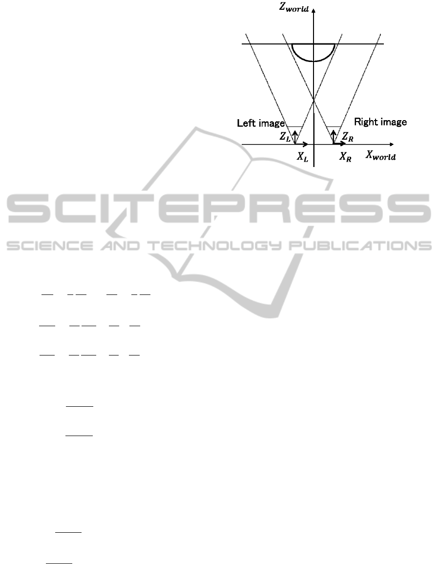
Figure 1: Two cameras coordinates and world coordinates
used for imaging and recovering in evaluations.
2.2 Multi-view Consistency
We define an objective function J
total
using two-view
images corresponding to a left image and a right im-
age,
J
total
≡ (1 − λ) (J
L
+ J
R
) + λJ
smooth
, (11)
where each of J
L
and J
R
indicates the integrated value
of the square errors of the image irradiance equations
at the left camera and the right camera respectively,
which corresponds to the integration part of the first
term in the right-hand side of Eq. 3 with the perspec-
tive modifications Eqs. 7-10. J
smooth
in this equa-
tion represents smoothness constraints, which corre-
sponds to the second term without λ in the right-hand
side of Eq. 3, but Z
2
XX
and Z
2
YY
are represented with
the world coordinate system placed at the interme-
diate position of both camera’s coordinates shown in
Fig. 1. By using the world coordinates, we can deal
with both of a left image and a right image equally to
recover a depth map. This objective function should
be minimized by varying the 3-D variables including
a depth map and a direction of a light source and so
on.
In our study, the dichromatic reflection model
(S.A.Shafer,1985) in which image intensity is defined
by a linear sum of diffuse and specular reflections is
adopted.
R = R
dif f use
+ R
specular
. (12)
To simplify the problem, we assume that the diffuse
and the specular reflections are constant on the object,
and the strength of both reflections are measured us-
ing the intensity of a light source as a unit. R
dif f use
indicates the diffuse reflection component. Using the
strength of the diffuse reflectance K
d
, a surface nor-
mal vector ~n and a unit vector
~
l indicating the direc-
VISAPP2013-InternationalConferenceonComputerVisionTheoryandApplications
336

tion of a parallel light source, R
dif f use
can be formu-
lated as follows:
R
dif f use i, j
= K
d
~n
i, j
·
~
l. (13)
R
specular
indicates the specular reflection component.
In this study, we apply the Phong’s reflection model
(Phong, 1975). In the same way, R
specular
is formu-
lated with the strength of the specular reflectance K
s
,
a unit vector~r denoting the direction of the reflected
light, a unit vector~v denoting the direction of a view
point and α indicating a highlight factor as follows:
R
specular i, j
= K
s
(~r
i, j
·~v
i, j
)
α
. (14)
In Eqs. 13 and 14, (~a ·
~
b) represents an inner prod-
uct of ~a and
~
b. In the formulation of R
i, j
, {Z
i, j
},
~
l,
K
d
, K
s
and α are concerned as unknown variables in
this study. However, in general, R
i, j
can have various
models and can include many unknown variables, for
example, the albedo distribution of the diffuse reflec-
tion and the intensity of a light source. Such an exten-
sion is an indispensable future work in the framework
of our strategy.
We discretize the X and Y axes of the world co-
ordinates, and represent the depth as the Z value at
the discretized (X,Y) position. To evaluate the value
of J
total
, the updated depth map defined in the world
coordinate as the above way is projected to both cam-
era images, and the depth values at all pixels in both
images are calculated using a interpolation technique.
We use Z
cam
as the depth value corresponding to a
certain pixel in the image of the camera. At each iter-
ation, Z
cam
is obtained with an adaptive interpolation
as follows:
Z
cam
=
4
∑
i=1
f
i
Z
i
world
, (15)
where {Z
i
world
}
i=1,···,4
means the depth values of the
neighboring four 3-D points in the world coordi-
nates, and f
i
indicates the interpolation weight hold-
ing
∑
4
i=1
f
i
= 1. In this study, we simply adopt a lin-
ear interpolation. Using also the updated other 3-D
variables, subsequently the values J
L
and J
R
are com-
puted respectively and those are summed up with a
same weight.
We minimize J
total
with decreasing λ from 1.0 to
0.0 using a coarse to fine technique based on a hi-
erarchical multi-resolution decomposition of images.
Minimization for each λ is performed by the conju-
gate gradient method. In our minimization, the vari-
ables to be recovered, i.e. {Z
i, j
},
~
l, K
d
, K
s
and α,
are updated reciprocally and individually. This mini-
mization procedure is repeated until convergence. To
lower J
total
repeatedly, we need derivatives with re-
spect to the each variable. Note that the exact dif-
ferentiation with respect to the depth is complicated,
-3
-2
-1
0
1
2
3
-3
-2
-1
0
1
2
3
5.9
6
6.1
6.2
6.3
6.4
6.5
6.6
Figure 2: True depth map using Z values represented with
world coordinates.
(a) (b)
Figure 3: Artificially generated image using the imaging
model shown in Fig. 1: (a) left camera image; (b) right cam-
era image.
since the depth values explicitly appearing in J
L
and
J
R
are the functions of the each camera’s coordinates.
To differentiate J
total
with respect to Z
i
world
, the fol-
lowing computation is required.
∂J
total
∂Z
i
world
= (1− λ)
(
K
L
∑
k=1
f
k
Li
∂J
L
∂Z
L
k
cam
+
K
R
∑
k=1
f
k
Ri
∂J
R
∂Z
R
k
cam
)
+λ
∂J
smooth
∂Z
i
world
,
(16)
where Z
L
k
cam
is the depth corresponding to the pixel in
the left camera image and is interpolated using Z
i
world
,
K
L
indicates the number of Z
L
k
cam
, and f
k
Li
is the inter-
polation weight of Z
i
world
for Z
L
k
cam
. Z
R
k
cam
, K
R
and
f
k
Ri
are defined in the same way. It is noted that, in
this study, there are no rotation between both camera
coordinates, and hence the light source direction
~
l is
common to both images. Therefore, the derivative of
J
total
with respect to
~
l needs no special techniques.
The other variables also can be derivative straightfor-
wardly.
3 NUMERICAL EVALUATIONS
3.1 Evaluation Methods
We used a very simple target object, i.e. a hemisphere
on the flat board placed perpendicular to an optical
axis. The coordinate systems including two cameras
ShapefromMulti-viewImagesbasedonImageGenerationConsistency
337
and the the world coordinates are shown in Fig. 1.
The true depth map used in the evaluations is shown
in Fig. 2. The parallel light source with the direc-
tion
~
l = (0.236, 0.236, −0.943) irradiates the object
and cameras are assumed as pin-hole cameras. The
strengths of both reflectances are defined as K
d
= xx
and K
s
= xx, and the highlight factor α = xx.
In Fig. 3(a), an artificially generated image for the
left camera under this condition. When this image is
only watched, an optical illusion occurs generally,and
human can recognize also spurious shape and light di-
rection. On the other hand, in Fig. 3(b) shows the im-
age generated for the right camera. To generate these
test figures, the surface normals ~n
i, j
s are calculated
analytically and used in Eq. 13, but when we recover
the 3-D variables, the first and the second differen-
tials are calculated in a discrete manner using Eqs. 7-
10. This discrepancy causes the error for the image
radiance equation defined by Eq. 1, although no in-
tensity noise is added explicitly. The spatial distance
between two cameras are set as 1 using a focal length
of the cameras as a unit. Since the both image in-
clude binocular disparity information, using the two
images we can recover the shape, and hence using
the recovered shape and images the light source di-
rection can be also determined. However, it is noted
that explicit disparity matching between these images
is difficult because of existing specular reflection, and
hence only the poor depth recoveryis performed. This
means that, in the evaluations, we can examine the
case where only the poor initial values are used.
Using these two figures, we define J
total
in Eq. 11
and minimize it to recover 3-D information, specifi-
cally a depth map, a light source direction, a highlight
factor related to a specular reflectance and strengths
of a diffuse reflectance and a specular reflectance us-
ing a intensity of a light source as a unit. In the re-
covery processing, as initial values, we use a plane
depth Z = 6.5, a light source direction parallel to op-
tical axis
~
l = (0.0, 0.0,−0.1), strengths of both re-
flectances K
d
= 0.5, K
s
= 0.5 and highlight factor
α = 2.0, and adopt 4 layer multi-resolution decompo-
sition of images. Those initial values are determined
heuristically.
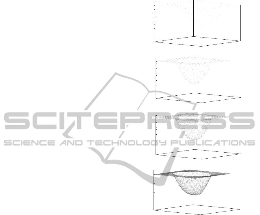
3.2 Evaluation Results
The depth maps for each hierarchical stage recovered
from two views are shown in Fig. 4. The RMSE
of the recovered depth at 4th layer is 9.85 × 10
−3
,
the inner product of recovered
~
l and true value is
1.00, the relative errors of the other parameters are
respectively K
d
= 2.47× 10
−2
, K
s
= 3.89× 10
−2
and
α = 6.43 × 10
−2
. In Fig. 5, the re-generated images
(a)
0
2
4
6
8
10
12
0
2
4
6
8
10
12
5.9
6
6.1
6.2
6.3
6.4
6.5
6.6
(b)
0
5
10
15
20
25
30
0
5
10
15
20
25
30
6
6.05
6.1
6.15
6.2
6.25
6.3
6.35
6.4
6.45
6.5
6.55
(c)
0
10
20
30
40
50
60
0
10
20
30
40
50
60
6
6.05
6.1
6.15
6.2
6.25
6.3
6.35
6.4
6.45
6.5
6.55
(d)
0
20
40
60
80
100
120
0
20
40
60
80
100
120
6
6.1
6.2
6.3
6.4
6.5
6.6
Figure 4: Recovered depth from two-view images: (a) at
first layer with 13× 13 pixels; (b) at 2nd layer with 27× 27
pixels; (c) at 3rd layer with 54× 54 pixels; (d) at 4th layer
with 108× 108 pixels.
using the recovered 3-D quantities for the both camera
are shown, and the RMSEs of those and input images
are 6.80× 10
−3
for the left camera and 6.51 × 10
−3
for the right camera. From these results, unknown
quantities related to an image generation, such as a
depth, can be recovered using the image generation
consistency from multi-views despite the difficulty of
disparity detection caused by specular reflection.
Subsequently, we confirm usefulness of using
multi-viewimages. Fig. 6 shows the depth map recov-
ered by using only the right camera image and defin-
ing objective function with (1 − λ)J
R
+ λJ
smooth
. The
RMSE of the recovered depth is 4.54 × 10
−2
, the in-
ner product of recovered
~
l and true value is 0.990, the
relative errors of the other parameters are respectively
K
d
:8.65×10
−2
, K
s
: 7.11×10
−1
and α : 6.28×10
−1
.
VISAPP2013-InternationalConferenceonComputerVisionTheoryandApplications
338

(a) (b)
Figure 5: Re-generated image using 3-D quantities recov-
ered from two-view images: (a) left camera image; (b) right
camera image.
0
20
40
60
80
100
120
0
20
40
60
80
100
120
6
6.1
6.2
6.3
6.4
6.5
6.6
Figure 6: Recovered depth from only right camera image.
The errors are larger for the case of using two-view
images. By comparing the minimized value of the
objective function, J
total
corresponding to the result
in Fig. 4(d) divided by 2 is 2.65 × 10
−4
and J
R
is
2.53 × 10
−4
. It is noted that λ = 0 when the objec-
tive function is minimized finally. This means that
the objective function for only the right camera is
minimized to the the same level with the objective
function for the both camera. The RMSE of the re-
generated image for the right camera and input image
is 9.19 × 10
−3
, hence it is shown in Fig. 7 (b) that
the recovered 3-D quantities generate the image suf-
ficiently close to the input image of the right camera.
Fig. 7 (a) shows the left camera image generated by
the recovered 3-D quantities from only the right cam-
era image, and the RMSE of that and the original left
camera image is 4.16× 10
−2
. This result denotes that
the image generation constraint from only one-view
point does not have enough information, and the im-
age generation consistency from multi-view prevents
falling an erroneous solution.
(a) (b)
Figure 7: Re-generated image using 3-D quantities recov-
ered only from right camera image: (a) left camera image;
(b) right camera image.
4 CONCLUSIONS
In this paper, we discussed the unification strategy
of various clues for shape from X. The feature-based
clues are desirable for mainly obtaining the initial val-
ues for the unification processing based on an image
generation constraint. The unification strategy pro-
posed in this paper mainly consists of forward com-
putations, i.e. computer graphics computations. On
the other hand, the methods using the feature-based
clues can be considered to be used for solving the in-
verse problems. Hence, it is necessary that a wide
and profound discussion about the way for combin-
ing a feature-based method and an image generation
constraint method. To minimize the objective func-
tion using an image generation consistency, which is
strongly asserted in this study, effectively and/or sta-
bly, the feature-based clues may be used powerfully
to update the values to be determined.
In this paper, we showed only that the image gen-
eration consistency can be used for the problem which
can not be solved uniquely or accurately by each of
the usual shading method and the disparity detection
individually. Our strategy is expected to be powerful
especially if there are the vague distributions of a dif-
fuse and a specular reflectance, in which a binocular
disparity detection is drastically difficult and hence,
the unification based on the image generation consis-
tency is increasingly effective to update the rough and
bad initial depth. Now, we are examining and gen-
erating the algorithm for this situation based on the
image generation constraint.
Additionally, we can expand our multi-view strat-
egy toward a temporal processing. By using im-
age sequence, the previously recovered 3-D quantities
can be known and only the change between frames
should be computed with small computation costs.
The Kalman filter technique can also be applied and
hence, it is expected that the reliability of the recov-
ered 3-D quantities increases over time.
REFERENCES
Brooks, M. J. and Horn, B. K. P. (1985). Shape and source
from shading. In proc. Int. Joint Conf. Art. Intell.,
pages 18–23.
Hayakawa, H., Nishida, S., Wada, Y., and Kawato, M.
(1994). A computational model for shape estimation
by integration of shading and edge information. Neu-
ral Networks, 7(8):1193–1209.
Horn, B. K. P. (1990). Height and gradient from shading.
Int. J. Computer Vision, 5(1):37–75.
Lazaros, N., Sirakoulis, G. C., and Gasteratos, A. (2008).
ShapefromMulti-viewImagesbasedonImageGenerationConsistency
339

Review of stereo vision algorithm: from software to
hardware. Int. J. Optomechatronics, 5(4):435–462.
Leclerc, Y. G. and Bobick, A. F. (1991). The direct com-
putation of height from shading. In proc. CVPR ’91,
pages 552–558.
Maki, A., Watanabe, M., and Wiles, C. (2002). Geotensity:
combination motion and lighting for 3d surface recon-
strcution. Int. Journal of Comput. Vision, 48(2):75–
90.
Phong, B. T. (1975). Illumination for computer generated
pictures. Communication of the ACM, 18(6):311–317.
Poggio, T., Gamble, E. B., and Little, J. J. (1988). Parallel
integration of vision modules. Science, 242:43–440.
Samaras, D., Metaxas, D., Fua, P., and Leclerc, Y. G.
(2000). Variable albedo surface reconstruction from
stereo and shape from shading. In proc. Int. Conf.
CVPR, volume 1, pages 480–487.
S.A.Shafer (1985). Using color to separate reflection com-
ponents. Color Research and Application, 10(4):210–
218.
Szeliski, R. (1991). Fast shape from shading. CVGIP: Im-
age Understanding, 53(2):129–153.
Terzopoulos, D. (1983). Multilevel computational pro-
cesses for visual surface reconstruction. Computer Vi-
sion, Graphics, and Image Processing, 24:52–96.
Wakabayashi, K., Tagawa, N., and Okubo, K. (2012). Di-
rect computation of depth from shading for perspec-
tive projection. In proc. Int. Conf. Comput. Vision,
Theory and Applications, pages 445–448.
Zhang, R., Tsai, P.-S., Cryer, J. E., and Shah, M. (1999).
Shape from shading: A survey. IEEE Trans. PAMI,
21(8):690–706.
VISAPP2013-InternationalConferenceonComputerVisionTheoryandApplications
340
