
Contactless Electrical Bioimpedance System for Monitoring Ventilation
A Biodevice for Vehicle Environment
Ra
´
ul Mac
´
ıas Mac
´
ıas, Miguel
´
Angel Garc
´
ıa Gonz
´
alez, Juan Ramos Castro, Ramon Brag
´
os Bardia
and Mireya Fern
´
andez Chimeno
Department of Electronic Engineering, Universitat Polit
`
ecnica de Catalunya, Campus Nord,
Edifici C-4 08034, Barcelona, Spain
Keywords:
Bioimpedance, Ventilation, Contactless Electrodes, Textrodes, Automotive.
Abstract:
Nowadays, automotive companies are focused in improving road traffic safety. For that, not only the vehicle
performance is improved but also the driver behavior is monitored. This could be done in many ways. One of
them is to monitor a specific physiological parameter using a biodevice. That device should be reliable enough
to use in a very noisy environment like a vehicle is. Furthermore, because long-term monitoring is required,
any invasive and annoying method should be avoided. Therefore, an electrical bioimpedance device capable
of monitoring driver ventilation using several textiles electrodes has been designed and implemented.
1 INTRODUCTION
In recent years one of the main goals of the automo-
tive industry is to improve the road safety. Because of
most of traffic crashes occur during the appearance of
non-appropriate states for driving, e.g. drowsy driv-
ing or drunk driving (Anund et al., 2008), apart from
improving the vehicle performance, monitoring the
driver behavior is also required. To achieve that, sev-
eral systems are being tested. These systems can be
mainly classified on three types. First type is based
on driving performances i.e. unintended lane depar-
tures, steerings and brakes. The second one is based
on camera systems that detect the percentage of eye
closure (PERCLOS), head movements and blinkings.
Finally, the third type is based on recording biomed-
ical signals. In (Michail et al., 2008), signals from
electroencephalography (EEG), electrocardiography
(ECG) and heart rate variability (HRV) are used. On
the other hand, electroocculography (EOG) and venti-
lation are used in (Lal and Craig, 2001) and in (Folke
et al., 2003), respectively.
Focusing on the third type, regardless of the phys-
iological parameter to be measured, any biodevice
should fulfill three requirements at least. Firstly, the
biodevice must be capable of recording signals in a
very noisy environment. In a vehicle, there are not
only artifacts produced by the car engine but also arti-
facts caused by other reasons like body motion or the
state of the roads. As for the second feature, a long-
term monitoring system is required because the ap-
pearance of non-appropiate states while driving is a
slow process. Moreover, the device should also be
non-invasive and non-annoying to allow the driving
as comfortable as possible. Therefore, the use of hos-
pital devices is not recommended and the design of
new biodevices is required.
Thus, this paper shows a new biodevice suitable
for automotive applications. This device consists of
an electrical bioimpedance (EBI) system capable of
monitoring the ventilation, and also the heart rhythm,
using textile electrodes. These electrodes are placed
on the steering wheel and also in the car seat. In addi-
tion, this paper also shows some results according to
some parameters such as the electrode configuration,
the frequency of the injected signal and the clothing
thickness.
2 SYSTEM
As mentioned above, the biodevice is based on an in-
strumentation system of EBI. This allows to monitor
signals from the driver by textiles electrodes. The de-
vice is designed following the guidelines shown in
(Riu et al., 2009). In addition, in order to avoid the
impedance of the electrodes, the EBI system is based
on the four-wire method proposed by (Schwan and
Ferris, 1968).
Thus, as shown in figure 1, the biodevice can be
14
Macías Macías R., Ángel García González M., Ramos Castro J., Bragós Bardia R. and Fernández Chimeno M..
Contactless Electrical Bioimpedance System for Monitoring Ventilation - A Biodevice for Vehicle Environment.
DOI: 10.5220/0004195800140020
In Proceedings of the International Conference on Biomedical Electronics and Devices (BIODEVICES-2013), pages 14-20
ISBN: 978-989-8565-34-1
Copyright
c
2013 SCITEPRESS (Science and Technology Publications, Lda.)

divided into three main blocks:
• Signal Generator (GEN).
• Analog Front-End (AFE).
• Demodulator and Acquisition (DEM).
Figure 1: A block diagram of the EBI device. The striped
areas are the possible placements of the driving electrodes.
In light color, the possible placements of the sensing elec-
trodes.
2.1 Signal Generator
Signal generation can take several forms, e.g. from
a simple linear oscillator or digital clock to a Direct
Digital Synthesizer (DDS) able to produce sinusoidal
waveforms or arbitrary waveforms in a wide range
of frequencies and amplitudes. In this case, and be-
cause of hardware limitations, the selected option is
to generate by a microcontroller, PIC18F1320, an ad-
justable amplitude single tone waveform of 62.5 kHz.
Later, this signal is used also as the reference sig-
nal in the demodulator block.
2.2 Analog Front-end
Once the signal is generated, this is sent to an AFE.
Basically, the AFE consists of two main stages. In
the first stage, the AFE injects an excitation signal
through a pair of driving electrodes. In the second
one, a pair of sensing electrodes are used to measure
the voltage difference which is related to the proper-
ties of the tissue.
2.2.1 Current Injection Stage
The excitation signal is sent to a differential-
differential amplifier, AD8138. However, instead of
applied directly the voltage of these two outputs to
the driving electrodes, each one is used as an input of
a voltage-current (V-I) converter based on a second-
generation current conveyor (CCII). Thus, the V-I
converter acts as a voltage-controlled current source
(VCCS), (Bragos et al., 1994). In this way, using
current driving instead of voltage driving achieves a
current limiting mechanism and reduces the possible
nonlinearities. So the guidelines of safety risks pro-
vided by the IEC-60601-1 standard can be fulfilled.
In this case where a 62.5-kHz frequency current is in-
jected, the current limit is established in 6.250 mA.
In addition, as there are filter capacitors to avoid
the flow of the Direct-Current (DC) current to the
body, in this stage a DC feedback of the CCII is also
required to avoid saturation problem.
2.2.2 Voltage Sensing Stage
In the voltage sensing stage, a differential to single
ended voltage conversion is done by a wideband dif-
ferential amplifier. However, before this conversion,
the voltage difference between the pair of sensing
electrodes is measured by a pair of high-impedance
buffers. These buffers are used because of their input
impedances are higher than the input impedance of
the differential amplifier. Furthermore, these buffers
also allow to measure the common-mode voltage
without disturbing the signal quality.
In addition, as in the current injection stage, filter
capacitors are also required. Thus, to avoid the satu-
ration of the amplifiers the polarization currents of the
amplifiers should be as low as possible.
2.2.3 Common-mode Feedback Block (CMFB
Block)
Usually there is not a perfect isolation between the
current injection stage and the voltage sensing stage.
Thus, due to these unbalanced conditions a common-
mode voltage can exist. To reduce this voltage a feed-
back circuit with the appropiate negative open loop
gain is required. Furthermore, this feedback circuit
should also maintain the stability of the system.
2.2.4 Active Shielding
In order to reduce interferences from external elec-
tromagnetic fields and crosstalk between the driving
electrodes and the sensing ones, shielded cables are
used. The shield of these cables is connected to a cir-
cuitry. This circuitry drives the shield to a voltage
that is equal to the voltage in the internal wire. Due
to oscillation problems could appear at high frequen-
cies, a filter capable of reducing the gain below one at
high frequencies is also used at the input of the active
shielding circuitry.
ContactlessElectricalBioimpedanceSystemforMonitoringVentilation-ABiodeviceforVehicleEnvironment
15

2.3 Electrodes
As mentioned above, the electrodes should be as no-
invasive and no-annoying as possible for the driver.
Therefore, using standard metal electrodes seems to
be not the better option. In addition, as cited in
(Wheelwright, 1962),during long-term monitoring,
the hidrogel used with this kind of electrodes can
cause irritation and allergy problems.
So, in this system instead of using standard metal
electrodes, electrodes made of textiles, also called
textrodes, are chosen. In this way, not only irrita-
tion and allergy problems are solved but also a higher
comfort for the driver is achieved. However, the
main drawback of the textrodes is that the electrode
impedance, Z
ep
, shows a strong capacitive behavior,
(Beckmann et al., 2010). In addition, as the textrode is
not directly in contact the skin, this capacitive behav-
ior depends on the exerted pressure and factors related
to the clothing of the driver like material, thickness or
number of layers.
2.4 Demodulator & Acquisition
Although there are several demodulation techniques,
a switching demodulator is used. Switching demod-
ulators are based on a switch controlled by a square
signal. The frequency of this square signal is the same
that the signal generated by the microcontroller in the
signal generator block. After the switching demodu-
lator, the signal is driven to a third-order Sallen-Key
low-pass filter (LPF). Then using this output signal
from the LPF, the measured voltage is acquired. In
addition, by a high-pass filter (HPF) and a basic cir-
cuitry, the relative variations of the measured voltage
are also amplified and acquired. These voltage vari-
ations should be amplified before recording because
of their low amplitude and also the poor accuracy
that the 10-bit Analog-to-Digital Converter (DAC) of
the microcontroller can provide. Finally, the acquired
data are sent from the microcontroller to a computer
by a mini USB-Serial UART development module.
Thus, any software such as Matlab or LabVIEW can
be used later to process and to estimate the impedance
value.
3 MEASUREMENTS
To check that the biodevice works properly, several
measurements are carried out. These measurements
can be classified into three groups according to:
• Comparison to a reference signal.
• Configuration of electrodes, i.e, the placement of
the driving and sensing electrodes in the car seat
and steering wheel.
• Influence of the thickness of clothing.
Note the measurements were done in a simulation
environment where there are no interferences caused
by the state of the road or the car engine vibrations.
3.1 Comparison to a Reference Signal
In this group, several subjects are monitored by the
designed device and also by a commercial one made
by BIOPAC Systems. The commercial device ac-
quires at a sampling frequency of 1 kHz the ventila-
tion signal using a piezoresistive thoracic band. Then,
this signal is used as reference signal to verify the cor-
rect operation of the designed device.
It is worth mentioning that in this case, only the
proper behavior of the AFE is checked in fact. In-
stead of using the signal generator block and the de-
modulator block mentioned above, a National Instru-
ments Data Acquisition (DAC) module is utilized. By
this module, a single frequency sine wave of 300 kHz
is generated and In-phase Quadrature (IQ) demodu-
lation is done to obtain the real and imaginary part
of the signal at a sampling frequency of 25 Hz. Fi-
nally, using a Labview application, the magnitude and
the phase of the estimated impedance are saved. Note
that instead of generating a signal of 62.5 kHz, a sig-
nal of 300 kHz is applied. There are two reasons to
apply a higher frequency. First, using this DAC mod-
ule, the hardware limitation is less strong as the one
imposed by the generator and the demodulator blocks
described above. Second, the higher the frequency a
better response of the system is achieved because of
the capacitive behavior of the textile electrodes.
3.2 Configuration of Electrodes
In the second group of measurements, the biodevice is
checked according the placement of electrodes. Thus,
whereas the frequency of the injection signal is fixed
to 62.5 kHz, the place of driving and sensing elec-
trodes is changed, giving three configurations:
• Steering Wheel-steering Wheel Configuration.
• Steering Wheel-back Seat Configuration.
• Back Seat-back Seat Configuration.
In the steering wheel-steering wheel configura-
tion, a driving electrode and a sensing electrode are in
contact with the right hand of the driver. In the same
way, the other pair of driving-sensing electrodes and
the left hand are also in contact.
BIODEVICES2013-InternationalConferenceonBiomedicalElectronicsandDevices
16
On the other hand, in the second configuration,
whereas a driving and a sensing electrode remain in
the steering wheel, the other driving and sensing elec-
trode are moved to the upper half of the back seat.
Finally, in the back seat-back seat configuration,
instead of using the 4-wire technique, the 2-wire tech-
nique is carried out because of both textile electrodes
on the back seat act as driving and sensing.
3.3 Influence of the Thickness of
Clothing
In the last group of measurements, the relationship be-
tween the clothing and the measured signals is tested.
Therefore, using the steering wheel-back seat config-
uration, the ventilation of a subject is monitored under
the following states according to the clothes:
• Thin t-shirt.
• Thin jacket over thin t-shirt.
• Thick sweater over thin t-shirt.
4 RESULTS
As in previous section, the results are discussed based
on the three kinds of measurements.
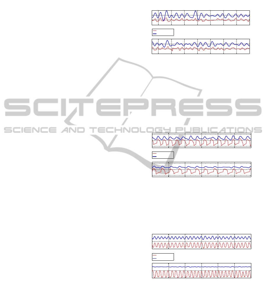
4.1 Comparison to a Reference Signal
As mentioned above, the signal acquired by the tho-
racic band acts as a reference to check the signal
from the designed biodevice. Thus, the biodevice
works properly if the measured signal fits to the refer-
ence, i.e. for the same period of time, the exhalation-
inhalation ratio is the same in both signals.
For each volunteer, two different configurations
are tested. In the upper graphs of the figures 2, 3 and
4, as a driving electrode and a sensing electrode are
in contact to the left hand, the second driving and the
second sensing electrode are placed in the right and
left side of the back seat, respectively. On the other
hand, in the bottom graphs whereas the electrodes on
the back seat remain at the same point, both electrodes
on the steering wheel are moved to the right side.
Note that for all cases except one (bottom graph in
figure 4), both signals, from the bioimpedance device
and from the thoracic band, match up. The special
case can be due to the lack of contact between any
textrode and the volunteer.
Furthermore, whereas the figures 2 and 4 show
a normal respiration rate, i.e. between 12 and 20
breaths per minute in adults and in normal conditions,
in the figure 3 a slower respiration rate, around 6-7
breaths per minute, can be observed.
50 60 70 80 90 100 110 120
−5
0
5
10
Time (s)
Magnitude(Ω)
Thoracic Band vs. Impedance Ventilation:
Right Hand − Back Seat Configuration
50 60 70 80 90 100 110 120
−5
0
5
10
Time (s)
Magnitude(Ω)
Left Hand − Back Seat Configuration
Thoracic Band
Impedance
Figure 2: Comparison between the Thoracic Band and the
Bioimpedance Device for the first volunteer. (Top) Configu-
ration where both driving electrodes, back seat and steering
wheel, are in the right side of the body. (Bottom) Config-
uration where the driving electrode of the steering wheel is
in the left hand and the other driving electrode is in the right
side of the back. In both plots, the upper line is related to
the bioimpedance device and the bottom one comes from
the thoracic band.
20 40 60 80 100 120 140
−20
0
20
Time (s)
Magnitude(Ω)
Thoracic Band vs. Impedance Ventilation:
Right Hand − Back Seat Configuration
20 40 60 80 100 120 140
−20
0
20
Time (s)
Magnitude(Ω)
Left Hand − Back Seat Configuration
Thoracic Band
Impedance
Figure 3: Comparison between the Thoracic Band and the
Bioimpedance Device for the second volunteer. (Top) Both
driving electrodes are in the right side of the body. (Bottom)
The driving electrode of the steering wheel is in the left the
other driving electrode is in the right side of the back.
20 40 60 80 100 120 140
−5
0
5
Time (s)
Magnitude(Ω)
Thoracic Band vs. Impedance Ventilation:
Right Hand − Back Seat Configuration
20 40 60 80 100 120 140
−5
0
5
Time (s)
Magnitude(Ω)
Left Hand − Back Seat Configuration
Thoracic Band
Impedance
Figure 4: Comparison between the Thoracic Band and the
Bioimpedance Device for the third volunteer. (Top) Both
driving electrodes are in the right side of the body. (Bottom)
The driving electrode of the steering wheel is in the left the
other driving electrode is in the right side of the back.
4.2 Configuration of Electrodes
In this group of measurements, the influence of the
placement of the electrodes in the measured signal is
ContactlessElectricalBioimpedanceSystemforMonitoringVentilation-ABiodeviceforVehicleEnvironment
17
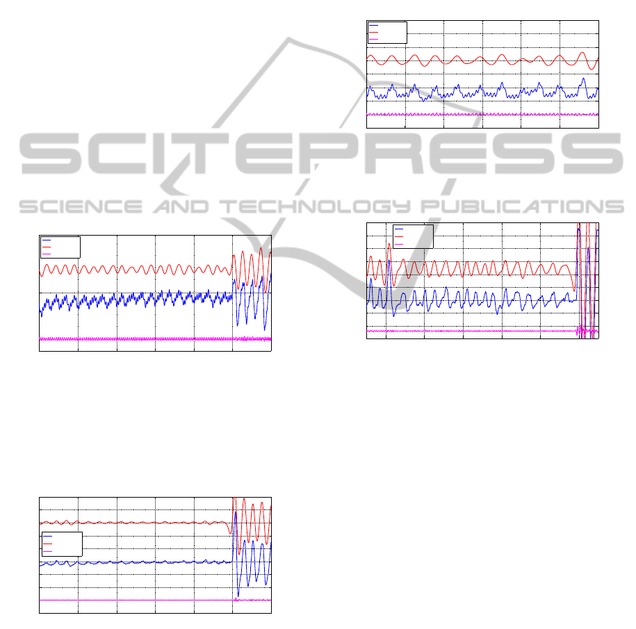
checked. Then, as mentioned above, three configura-
tions are tested. In any configuration, the same test
is done. The test consists of a two-minute monitor-
ing and, around the last 30 seconds, five deep breath-
ing are taken. It is worth mentioning that instead of
using the National Instruments DAC module, in this
group of measurements, and in the group below, the
signal generation block and the demodulation block
are based on a microcontroller which gives an injec-
tion signal of 62.5 kHz.
As shown in figures 5, 6, 7 and 8, three signals
are plotted. The middle one is the raw signal mea-
sured by the bioimpedance device and without pro-
cessing. Note that this signal is based on two compo-
nents: a low-frequency component, between 0.1 Hz
and 0.3 Hz, and a high-frequency component, over 1
Hz. Then, in the figures the upper signal is related to
the low frequency component of the raw data and the
bottom one is related to the high frequency compo-
nent. Furthermore, the low frequency signal and the
higher one are also related to the ventilation and the
cardiac rhythm, respectively.
20 40 60 80 100 120 140
−5
0
5
time(s)
Variations of Z(Ω)
Steering Wheel − Steering Wheel Configuration
Raw Data
Ventilation
Heartbeat
Figure 5: Steering Wheel - Steering Wheel Configuration.
(Middle) The raw data obtained from the bioimpedance de-
vice. (Top) The processed data after applying a simple soft-
ware band-pass filter, between 0.1 Hz and 0.3 Hz, to obtain
the ventilation signal. (Bottom) The processed data after
applying a simple software high-pass filter, over 1 Hz, to
obtain the signal related to the cardiac rhythm.
20 40 60 80 100 120 140
−20
−15
−10
−5
0
5
10
15
20
25
time(s)
Variations of Z(Ω)
Steering Wheel (Left Hand) − Back Seat Configuration
Raw Data
Ventilation
Heartbeat
Figure 6: Steering Wheel - Back Seat Configuration with a
driving electrode in the left hand and the other in the right
side of the back. (Middle) The raw data. (Top) The ven-
tilation signal. (Bottom) The signal related to the cardiac
rhythm.
Checking the figures 5, 6, 7 and 8, a first issue can
be observed. As in figures 5 and 7, the high frequency
component is noticed easily, in figure 8 this compo-
nent is insignificant. Therefore, either it is not possi-
ble to measure the signal related to the cardiac rhythm
using a 2-wire technique or using the designed biode-
vice, to be in contact directly to a hand is required to
obtain the high frequency component.
50 60 70 80 90 100 110
−3
−2
−1
0
1
2
3
4
5
time(s)
variations of Z(Ω)
Steering Wheel (Left Hand) − Back Seat Configuration
Zoom in 1−minute Period
Raw Data
Ventilation
Heartbeat
Figure 7: Zoom in to the figure 6 in a one-minute period.
(Middle) The raw data. (Top) The ventilation signal. (Bot-
tom) The signal related to the cardiac rhythm.
20 40 60 80 100 120
−15
−10
−5
0
5
10
15
20
25
30
time(s)
Variations of Z(Ω)
Back Seat − Back Seat Configuration
Raw Data
Ventilation
Heartbeat
Figure 8: Back Seat - Back Seat Configuration using a 2-
wire measurement technique. (Middle) The raw data. (Top)
The ventilation signal. (Bottom) The signal related to the
cardiac rhythm.
4.3 Influence of the Thickness of
Clothing
In the last group of measurements, dependencies on
clothing are checked. Applying the same test ex-
plained above and the steering wheel - back seat con-
figuration of electrodes, a subject is monitored wear-
ing three different clothing. In figure 9, the signal
is measured wearing a thin 100% cotton T-shirt. On
the other hand, over this T-shirt a thin 100% polyester
jacket and a thick sweater are worn in figures 10 and
11, respectively.
Note that the respiration rate is different in the
three figures. In figures 10 and 11, the respiration rate
is around 8 breaths per minute, lower than the mini-
mum respiration rate for normal condition in adults.
On the other hand, in figure 9 a normal rate of 11
breaths per minute can be observed. Furthermore, as
BIODEVICES2013-InternationalConferenceonBiomedicalElectronicsandDevices
18
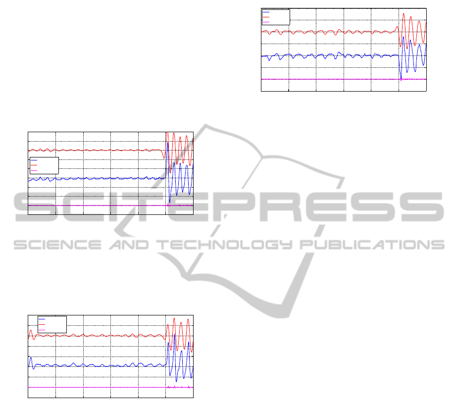
thicker the clothing, the measured signal is less sim-
ilar to the reference ventilation signal, refered to the
thoracic band.
Therefore, there seems to be a correlation between
clothing and the measured signal. Depending on the
clothings, the biodevice could not work properly be-
cause of some inhalations or exhalations cannot be
monitored. In fact, due to the capacitive behavior of
the textrodes, this problem could be solved using an
injection signal with a higher frequency.
20 40 60 80 100 120 140
−20
−15
−10
−5
0
5
10
15
20
25
time(s)
Variations of Z(Ω)
Steering Wheel (Left Hand) − Back Seat Configuration
Raw Data
Ventilation
Heartbeat
Figure 9: Steering Wheel - Back Seat Configuration with
the driving electrodes in the left hand and in the right side
of the back, respectively. The subject is wearing a thin T-
shirt made of cotton (100%). (Middle) The raw data. (Top)
The ventilation signal. (Bottom) The signal related to the
cardiac rhythm.
20 40 60 80 100 120 140
−15
−10
−5
0
5
10
15
20
25
time(s)
Variations of Z(Ω)
Steering Wheel − Back Seat Configuration wearing a Thin Jacket
Raw Data
Ventilation
Heartbeat
Figure 10: Steering Wheel - Back Seat Configuration with
the driving electrodes in the left hand and in the right side of
the back, respectively. The subject is wearing a thin jacket
made of polyester (100%) over a thin T-shirt made of cot-
ton (100%). (Middle) The raw data. (Top) The ventilation
signal. (Bottom) The signal related to the cardiac rhythm.
5 CONCLUSIONS
As shown in this paper, using a bioimpedance de-
vice, signals related to physiological parameters can
be monitored. In this particular case, not only sig-
nals related to the ventilation are measured but also
signals related to the cardiac rhythm. However, due
to the fact that the use of standard metal electrodes
are not recommended, new challenges related to the
textile electrodes arise. Thus, to analyze the behavior
20 40 60 80 100 120 140
−15
−10
−5
0
5
10
15
20
time(s)
Variations of Z(Ω)
Steering Wheel − Back Seat Configuration wearing a Thick Sweater
Raw Data
Ventilation
Heartbeat
Figure 11: Steering Wheel - Back Seat Configuration with
the driving electrodes in the left hand and in the right side
of the back, respectively. The subject is wearing a thick
sweater made of woolen (33%), polyester (27%), acrylic
(27%) and polyurethane (13%) over a thin T-shirt made of
cotton (100%). (Middle) The raw data. (Top) The ven-
tilation signal. (Bottom) The signal related to the cardiac
rhythm.
of the clothing-textrode interface in depth is required.
Furthermore, to test the bioimpedance device in a real
environment is also required.
But, in any case, the tests in a simulation environ-
ment show a proper operation of the biodevice. This
system is capable of monitoring the ventilation signal
just like a thoracic band. Furthermore, the biodevice
is also able to acquire the signal related to the car-
diac rhythm. Therefore, this biodevice seems to be
a further step to obtain a non-annoying non-invasive
biodevice capable of monitoring some physiological
parameters in a vehicle environment.
ACKNOWLEDGEMENTS
This work has been partially funded by the Span-
ish MINISTERIO DE CIENCIA E INNOVACI
´
ON.
Proyecto IPT-2011-0833-900000. Healthy Life style
and Drowsiness Prevention-HEALING DROP.
REFERENCES
Anund, A., Kecklund, G., Peters, B., and
˚
A kerstedt, T.
(2008). Driver sleepiness and individual differences
in preferences for countermeasures. Journal of Sleep
Research, 17(1):16–22.
Beckmann, L., Neuhaus, C., Medrano, G., Jungbecker, N.,
Walter, M., Gries, T., and Leonhardt, S. (2010). Char-
acterization of textile electrodes and conductors us-
ing standardized measurement setups. Physiological
Measurement, 31(2):233–247.
Bragos, R., Rosell, J., and Riu, P. (1994). A wide-band AC-
coupled current source for electrical impedance to-
mography. Physiological Measurement, 15(2A):A91–
A99.
ContactlessElectricalBioimpedanceSystemforMonitoringVentilation-ABiodeviceforVehicleEnvironment
19

Folke, M., Cernerud, L., Ekstr
¨
om, M., and H
¨
ok, B. (2003).
Critical review of non-invasive respiratory monitoring
in medical care. Medical & Biological Engineering &
Computing, 41(4):377–383.
Lal, S. K. L. and Craig, A. (2001). A critical review of the
psychophysiology of driver fatigue. Biological Psy-
chology, 55(3):173–194.
Michail, E., Kokonozi, A., Chouvarda, I., and Maglaveras,
N. (2008). EEG and HRV markers of sleepiness and
loss of control during car driving. In Conference pro-
ceedings : 30th Annual International Conference of
the IEEE. Engineering in Medicine and Biology Soci-
ety (EMBS)., volume 2008, pages 2566–9.
Riu, P., Bragos, R., and Rosell, J. (2009). In-
strumentation for Bio-impedance Measurements.
http://www.mn.uio.no/fysikk/english/people/aca/ogm
/index.html.
Schwan, H. P. and Ferris, C. D. (1968). Four-Electrode
Null Techniques for Impedance Measurement with
High Resolution. Review of Scientific Instruments,
39(4):481–485.
Wheelwright, C. D. (1962). Physiological sensors for use
in Project Mercury. NASA technical note ;NASA
TN D-1082. National Aeronautics and Space Ad-
ministration, Washington, D.C. [Online] Available
from: http://catalog.hathitrust.org/Record/011447015
[Accessed 12th April 2012].
BIODEVICES2013-InternationalConferenceonBiomedicalElectronicsandDevices
20
