
Method of Multislice CT Effective Doses Estimation on the Basis of
Dose Distribution Curves
Sergey Kruchinin and Mikhail Zelikman
Research and Practical Centre of Medical Radiology, Srednyaya Kalitnikovskaya, 28/1, Moscow, Russia
Keywords: CT, Effective Dose, Scattered Radiation.
Abstract: Conventional dose-length product method for CT effective dose evaluation in case of multislice scanners
with comparatively large X-ray beam collimation leads to underestimation of effective doses due to partly
neglecting of scattered in patient body radiation. It is possible to avoid this problem taking into account
“tails” of dose distribution on the length exceeds zone ±50 mm relative to the beam centre. Method of DLP
evaluation on the basis of dose distribution curves with “tails” estimated on full length (±200 mm or more)
is presented.
1 PURPOSE
Modern multislice CT scanners use X-ray beam
collimation of 30 – 40 mm or more and this leads to
increasing of scattered in patient body radiation and
its contribution to the effective dose as a result.
Traditionally effective doses evaluation for
various computed tomography exams is performed
on the basis of dose-length product (DLP) parameter
and conversion factors, specified for study type and
patient age by European Commission: as a rule adult
or child but sometimes child conversion factors are
presented more detailed
(European Commission’s
Study Group, 1999); (Deak et al., 2010). DLP in this
case is calculated using CT dose index (CTDI)
measurements on the length of 100 mm but when the
value of scattered radiation is significant this length
of dose integration becomes insufficient and results
in effective dose underestimation. Taking into
account dose distribution along z-axis on the length
of approximately ±200 mm (or more) relative to the
center of X-ray beam, provides an opportunity to
estimate CTDI and respectively DLP more correctly.
Features of method concerning DLP evaluation
on the basis of dose distribution curves with “tails”
estimated on the length of 200 mm or more (on each
side from X-ray beam centre) are described in the
paper.
2 METHODS AND MATERIALS
All the experiments (chest study parameters setting)
were conducted on the basis of two 64-slice CT
scanners: Aquilion 64 (Toshiba Medical Systems)
and Light Speed VCT (GE Healthcare). X-ray beam
collimation for CT units has been chosen in the
range from 32 to 40 mm.
Measuring of absorbed dose distribution along z-
axis has been performed utilizing CTDI cylindrical
phantoms (PMMA, “body” – 32 cm in diameter,
about 15 cm in length) and specially designed
cylindrical containers into each of which a set of
thermoluminescent dosimeters (TLDs) has been
placed. For experimental evaluation of absorbed
dose distribution on both sides from X-ray beam
centre (and plotting of corresponding curves) two
phantoms have been positioned close to each other
and this made possible to estimate in two steps
“tails” of absorbed dose distribution at the interval
of approximately ±200 mm along z-axis relative to
the beam centre. To plot a complete curve it is
necessary to combine the data obtained for the right
and the left sides of distribution.
Attention must be given for TLDs calibration
because utilized TLDs have a sensible dependence
of measured values on X-ray energy. It must be
taken into account that energy spectrum of scattered
radiation differs from that of the main beam. For this
reason the traditional calibration in air using
standard irradiation source (for example
137
Cs) or
91
Kruchinin S. and Zelikman M..
Method of Multislice CT Effective Doses Estimation on the Basis of Dose Distribution Curves.
DOI: 10.5220/0004184400910094
In Proceedings of the International Conference on Biomedical Electronics and Devices (BIODEVICES-2013), pages 91-94
ISBN: 978-989-8565-34-1
Copyright
c
2013 SCITEPRESS (Science and Technology Publications, Lda.)
CT scanner X-ray beam leads to substantial
distortions in dose estimates despite the fact that the
last method takes into account beam rotation
.TLDs
(LiF:Mg, Ti; 4.5±0.12 mm in diameter, 0.9±0.1 mm
thickness) from chosen group were placed inside a
container in which 22 – 24 sensors are housed
simultaneously. As a reference dosimeter Unfors Xi
with pencil type ionization chamber has been used.
Container with TLDs as well as Unfors Xi detector
were installed at the central and periphery holes of
CTDI phantom located in the centre of scanner
gantry and after this several exposures for one tube
rotation and with fixed table position have been
made. Multiple exposures are needed in order to
reliably exceed the sensitive threshold of
thermoluminescent dosimeters. Considering
reference device (Unfors Xi) readings and TLDs
measurements (estimates of an integral under
absorbed dose distribution curve on ±50 mm
interval) two values of the weighted CTDI have
been calculated and their ratio gives the calibration
factor for testing TLDs group.
Effective doses on DLP basis have been
calculated in respect that conversion factor for adult
chest studies in accordance with appropriate
document is equal to 0.017 mSv·mGy
-1
·cm
-1
(European Commission’s Study Group, 1999).
An adult (hermaphrodite) anthropomorphic body
phantom consists of 25 mm elements simulating
human body organ sections with different densities.
This phantom with TLDs (about 100 sensors) placed
inside was chosen for reference measurements. One
phantom section with thermoluminescent sensors
housed in is shown on Fig.1, as an example. TLDs
distribution in phantom was the following: red bone
marrow – 7; colon – 5; lungs – 24; stomach – 4;
breast – 2; gonads – 2; bladder – 2; liver – 5;
esophagus – 8; thyroid – 6; skin – 11; bone surface –
10; remind organs – 13. Using an anthropomorphic
phantom+TLDs, effective dose evaluation has been
made on the basis of weighting factors for different
organs and tissue presented in International
Commission on Radiological Protection (ICRP)
documents: ICRP Publication 60 and ICRP
Publication 103 recommendations (ICRP, 1991);
(ICRP, 2007).
3 RESULTS AND DISCUSSION
The right parts of absorbed dose distribution curves
received at the central and periphery holes of
doubled CTDI “body” phantom are presented on
Fig.2 and Fig.3 respectively. Fig.4 shows the right
parts of weighted distribution curves. Full length
weighted curves have been used for weighted CTDI
calculation on the basis of integrals under the curves
on the interval from –200 to +200 mm). Weighting
has been made using weighted factors 1/3 and 2/3
for centre and periphery zones respectively. It
follows from the received data that the integrals
under the absorbed dose distribution curves at the
central hole of doubled CTDI phantom (in the range
of ±200 mm) differ from the integrals on the interval
from –50 to +50 mm (traditional CTDI method)
approximately by (53 – 65)% for both scanners. For
periphery holes this difference is not so significant
and is about (11 – 13)%. Mentioned above means
that ignoring of scattered radiation outside ±50 mm
zone along z-axis leads to underestimation of the
effective dose up to approximately 20% in average
when using the traditional method on the basis of
single CTDI "body" phantom and 100 mm
ionization chamber (weighted CTDI) in case of
collimation 32 – 40 mm.
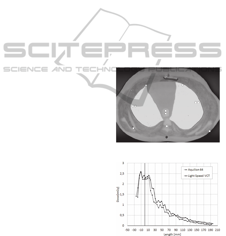
Figure 1: Anthropomorphic phantom section with TLDs
housed in.
Figure 2: The right part of absorbed dose distribution at
the centre hole of doubled CTDI phantom.
BIODEVICES2013-InternationalConferenceonBiomedicalElectronicsandDevices
92
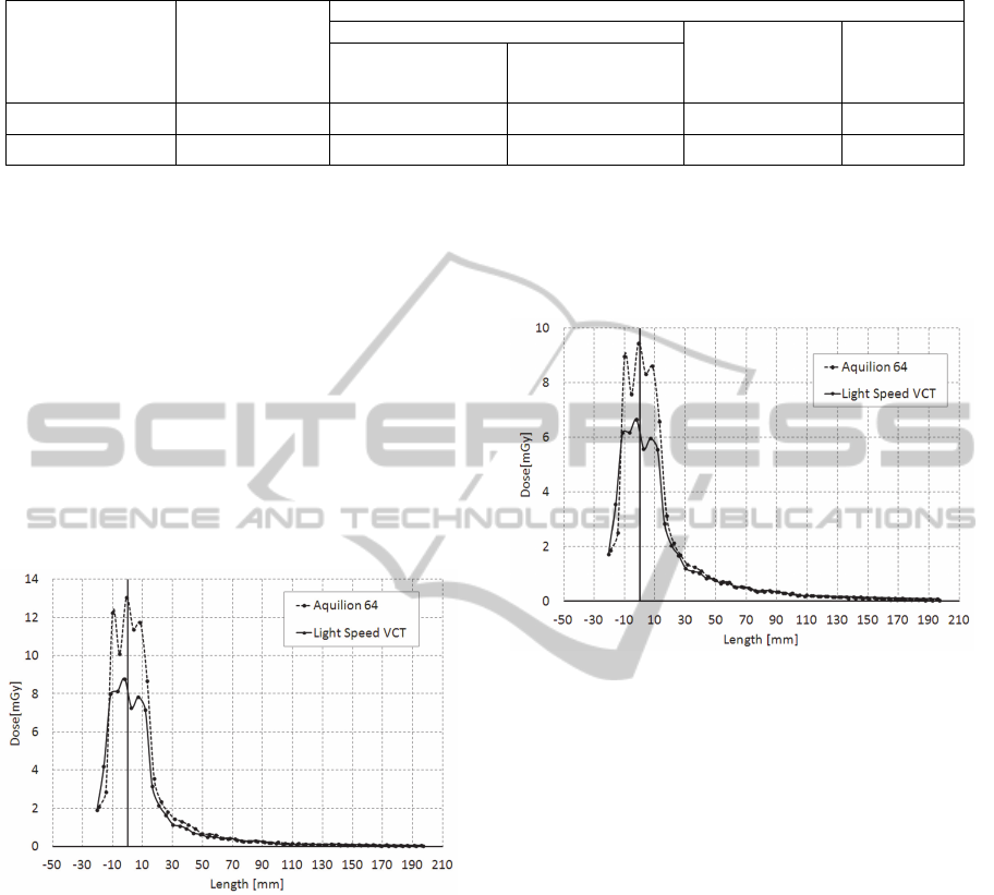
Table 1: Effective dose estimates obtained on the basis of various methods.
CT scanner type
X-ray beam
collimation, mm
Effective dose estimates, mSv
Anthropomorphic body phantom + TLDs
DLP parameter
method
Dose
distribution
curves
method
60 ICRP
Recommendations
103 ICRP
Recommendations
Aquilion 64
32 6,98 7,98 6,47 7,57
Light Speed VCT
40 6,53 7,61 5,54 6,66
After the experimental receiving of weighted
CTDI for one tube rotation and with fixed patient
table position (taking into account dose distribution
outside ±50 mm zone along z-axis), knowing pitch
and scanning length, it is possible to calculate DLP
parameter and patient effective dose as a result.
Effective dose estimates achieved on the basis of
conventional DLP method, anthropomorphic body
phantom+TLDs (60 and 103 ICRP Publications
recommendations) and proposed method utilizing
dose distribution curves are presented in Table 1.
Electrical parameters settings for both devices have
been chosen as close as possible (X-ray tube voltage,
current and time of one tube rotation).
Figure 3: The right part of absorbed dose distribution at
the periphery hole of doubled CTDI phantom.
The results obtained using presenting method are
very close to reference estimations based on
anthropomorphic phantoms+TLDs measurements.
Difference for chest exams on both CT scanners
does not exceed 8%. When compared it must be
taken into account that doses evaluated using
weighted factors from ICRP 103 Publication
recommendations exceed those based on ICRP 60
Publication recommendations by approximately 14 –
16% (15% in average) and that effective dose
conversion factors recommended by European
Commission have been calculated using Monte-
Carlo simulation method in 1999 when there were
ICRP 60 Publication recommendations only. Up to
now for ICRP 103 Publication recommendations
appropriate conversion factors are calculated for CT
scanner Somatom Sensation 64 (Siemens
Healthcare) only (Deak et al., 2010).
Figure 4: The right part of weighted dose distribution in
doubled CTDI phantom.
4 CONCLUSIONS
The presented method allows estimating of CT
effective doses more accurately in comparison with
traditional DLP procedure by taking into account of
scattered in patient body radiation outside ±50 mm
scanning zone along z-axis.
In this case patient effective dose evaluation
accuracy increases by approximately 20% (chest
exams) for considered models of 64-slice CT
scanners.
Since the use of traditional DLP method for
multislice CT scanners with large beam collimation
(30 – 40 mm and more) leads to underestimation of
patient effective dose, it seems necessary to utilize
presented method or, as an alternative, to calculate a
set of correction factors for widely used now
weighted CTDI values which are displayed on
scanner’s console for various types of CT studies.
Additionally these correction factors should take
into account differences in dose evaluation using
ICRP 103 Publication and ICRP 60 Publication
MethodofMultisliceCTEffectiveDosesEstimationontheBasisofDoseDistributionCurves
93

recommendations.
REFERENCES
Deak, P., Smal, Y. and Kalender, W. 2010, ‘Multisection
CT protocols: sex- and age- specific conversion
factors used to determine effective dose from dose-
length product’, Radiology, vol. 257, no.1, pp. 158 –
66.
European Commission’s Study Group 1999, European
Guidelines on Quality Criteria for Computed
Tomography (EUR 16262 EN), Luxembourg,
European Communities.
ICRP 1991, 1990 Recommendations of the International
Commission on Radiological Protection (Publication
60), ann. ICRP 21, no. 1 – 3.
ICRP 2007, 2007 Recommendations of the International
Commission on Radiological Protection (Publication
103), ann. ICRP 37, no. 2 – 4.
BIODEVICES2013-InternationalConferenceonBiomedicalElectronicsandDevices
94
