
RECENT SPS PROJECTS IN JAPAN
Naoki Shinohara
Research Institute for Sustainable Humanosphere, Kyoto University, Gokasho, Uji, Kyoto, Japany
shino@rish.kyoto-u.ac.jp
Keywords: Solar Power Satellite, SPS, Wireless Power Transmission, Microwave Power Transmission, Phased Array
Abstract: Solar Power Satellite/Station (SPS) is one of important energy system in future, which is
supported by radio wave technologies. The electric power which is generated in the SPS is
transmitted to the Earth by microwave or laser. We need a high efficiency and light weight for
microwave power transmission (MPT) system in order to reduce total cost of the SPS. There
were some MPT phased array, for example, a phased array in the MILAX experiment in 1992 in
Japan, a magnetron phased array in MPT airship experiment in 2009 in Japan, and a phased array
in the Hawaii experiment in 2008 in US and Japan. However, there were not enough for the
future SPS. Recently in Japan, there are two trials to develop a MPT phased array. One is a new
phased array for collaborative inter-universities researches, which has been developed in Kyoto
University in FY2010. The other is the SPS research and development project, in which we are
developing thin and high efficiency phased array for MPT from FY2009. The Japanese SPS
projects are based on ‘Basic plan for space policy’ which was established by Strategic
Headquarters for Space Policy in June 2009. Beam forming and target detecting algorisms and
technologies are also as important as the development of the high efficiency and light weight
phased array. There are various beam forming and target detecting techniques for the SPS, for
example, retrodirective target detecting with a pilot signal, Rotating Electromagnetic Vector
(REV) method, Position and Angle Correction (PAC) method, etc. The Japanese SPS projects
involve the verification of the various beam forming and target detecting techniques. In this
paper, I show mainly developments of phased array and beam forming and target detecting
techniques in the recent Japanese SPS projects.
1 INTRODUCTION
In June, 2009, Japanese Government established
‘Basic plan for space policy’ in order to expand
Japanese space activities and technologies. In the
plan, the SPS was selected on measure nine systems
and programs for the utilities and R&D of space as
follows;
“As a program that corresponds to the following
major social needs and goals for the next 10 years, a
Space Solar Power Program will be targeted for the
promotion of the 5-year development and utilization
plan.” and “Government will conduct ample studies,
then start technology demonstration project in orbit
utilizing "Kibo" or small sized satellites within the
next 3 years to confirm the influence in the
atmosphere and system check.”(Basic plan for space
policy1, 2009) (Basic plan for space policy2, 2009).
Three years passed from the establishment of the
Basic plan for space policy. During three years,
Japanese government has changed from
the Liberal
Democratic Party, which had political power for a
long time, to the Democratic Party of Japan.
Unfortunately, there was less progress of the space
policy by the Democratic Party of Japan in Japan in
this three years. However, in June 20 , 2012,
Japanese government established new law
concerning space development which is called “Law
of partly improvement of law of establishment of
Cabinet Office”. In the new law, they declare that
Cabinet Office will have jurisdiction over Japanese
space development instead of several Ministries,
including Ministry of Education, Culture, Sports,
Science and Technology which has jurisdiction over
JAXA, which had jurisdiction over the Japanese
space development simultaneously. They also
declare that new space policy decision commission
th
19
Shinohara N.
RECENT SPS PROJECTS IN JAPAN.
DOI: 10.5220/0005413400190023
In Proceedings of the First International Conference on Telecommunications and Remote Sensing (ICTRS 2012), pages 19-23
ISBN: 978-989-8565-28-0
Copyright
c
2012 by SCITEPRESS – Science and Technology Publications, Lda. All rights reserved
will be established instead of old Space Activities
Commission which leaded the Japanese space
activities. Seven members of new space policy
decision commission are selected in July 26 , 2012.
Prof. Hiroshi Matsumoto of Kyoto University, Prof.
Hiroshi Yamakawa of Kyoto University, and Prof.
Shin-ichi Nakasuka of University of Tokyo are the
members of new space policy decision commission.
th
Under the tempestuous circumstance of
Japanese space policy, the Japanese SPS project
and related development of a microwave power
transmission (MPT) are making our way.
2 DEVELOPMENT OF PHASED
ARRAY IN JAPAN
From FY2009, J-spacesystems (former USEF) starts
the SPS and the MPT R&D project(Fuse, 2011). The
author is committee chair of the assessment
committee of the project. The purposes of the project
are (1) development of high efficiency phased array
and rectenna array, and (2) field MPT experiment
with the developed phased array and rectenna. A
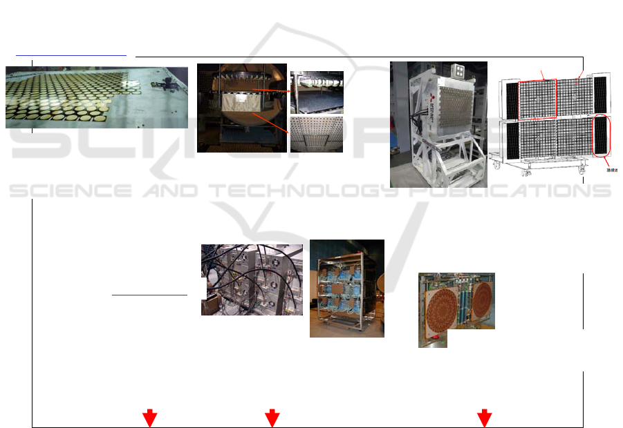
historical review of the phased array is shown in
Fig.1. There are two kinds of the phased array. One
is a phased array with semi-conductors. The other is
a phased array with magnetrons which are mainly
developed in Kyoto University, Japan. There are a
lot of the phased array for radar and SAR in the
world. However, the phased array for the MPT and
the SPS requires higher accuracy of beam forming
with higher efficiency of DC-RF conversion than
those for the radars. The newest phased array, which
will be developed in J-spacesystems’ SPS project in
FY2013, will have thinnest thickness (<4cm),
highest efficiency (>70% at HPA) at 5.8GHz with
GaN semi-conductor and MMIC technologies.
1990 2000 2010
1992 (for Airplane Experiment)
2.45GHz, Total Power >1.2kW
96 array module, 3in1 sub-array
HPA PAE >40%
Semi-Conductors
(GaAs)
By Kyoto Univ. and Kobe Univ.
Rear : Solar Cells
Front : Phased Array
10x10
Receiving Antenna (Rectenna)
Lights as Sun
METLAB
in Kyoto Univ.
SPSLAB
in Kyoto Univ.
A-METLAB
in Kyoto Univ.
2000 SPTITZ (for SPS)
5.8GHz, Total Power >25W
100 array module with Solar Cell,
System Eff. >15% (GaAs)
by JAXA and Kyoto Univ.
2010 5.8GHz,
Total Power >1.9kW
256 array module
thickness <30cm
in Kyoto Univ.
HPA PAE >70% (GaN)
2013 5.8GHz,
Total Power >1.6kW
304 array module
4in1 sub-array
By METI&USEF
HPA PAE >70% (GaN)
thickness <4cm
Magnetrons
2000 SPORTS2.45
2.45GHz, Total Power >4kW
Eff. >70% in Kyoto Univ.
12 magnetron array
2001 SPORTS5.8
5.8GHz, Total Power >2.7kW
Eff. >65% in Kyoto Univ.
2009 for Airship Exp.
2.45GHz, Total Power >440W
2 magnetron array in Kyoto Univ.
9 magnetron array
Fig.1 History of Developed Phased Array for MPT
At the end of FY2010, a new phased array was
installed in Kyoto University as multipurpose
research equipment(Honma, 2011)(Yamanaka,
2010). The characteristics of the phased array in
Kyoto University are as follows:
1) 5.8 GHz CW, no modulation.
2) Separated module antenna/active circuits
system.
3) Rigid antenna plane.
4) 256 elements.
First International Conference on Telecommunications and Remote Sensing
20
5) Active phased array with one active circuit for
one antenna.
6) 1.5 kW output microwave power.
7) F-class power amplifiers with GaN FETs.
8) >7 W output in high-power amplifier as final
stage.
9) >70% power added efficiency in microwave
high-power amplifier as the final stage (Fig. 21).
10) >40% as total DC-microwave conversion
efficiency.
11) 5-bit MMIC phase shifters.
12) <30 cm thickness as universal experimental
equipment.
The phased array system consists of phased array
equipment, beam control units, and a cooling unit.
The beam control units consist of an antenna control
unit, a PC, and the retrodirective equipment. The
rectenna array system consists of the rectenna array,
a DC/DC converter, a load, and the retrodirective
equipment.
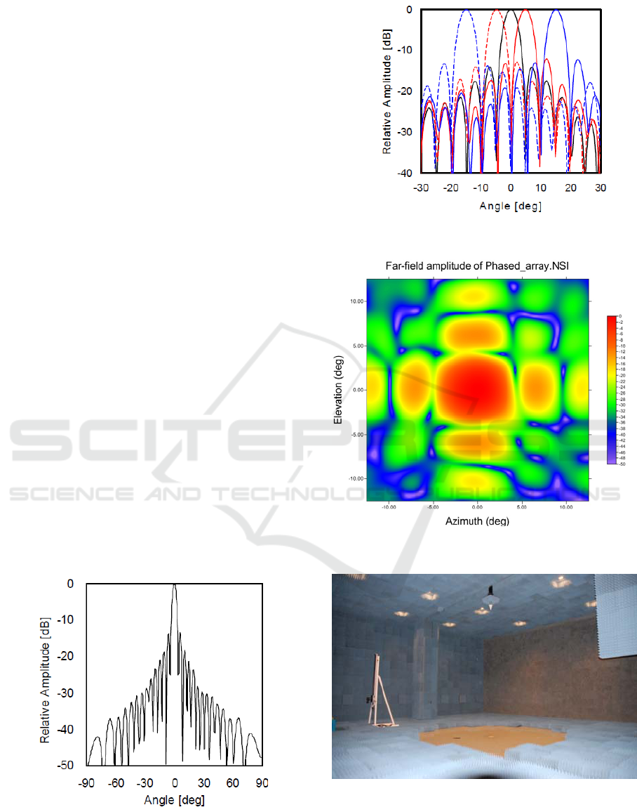
Figure 2 shows a simulated beam pattern, and
Fig. 3 shows measured beam patterns when the main beam
is steered to EL = (−15, −10, −5, 0, 5,10, 15) degrees. In
each beam steering angle, the obtained steering accuracy
was within 0.1 degrees.
Figure 4 shows measured azimuth-elevation beam pattern
which is measured by near field scanner in Kyoto
University. The near field scanner is installed in new
anechoic chamber called Advanced METLAB with the
phased array at the same time (Fig.5). It is plane-polar
type near field scanner. It can measure the multi-beam
pattern with control of beam direction of the phased array
simultaneously. It can also measure the 10mφ and
10kWCW phased array of satellite for the SPS. The
phased array and the near field scanner are open for use by
inter-universities and international collaborative studies.
We would like use the research facilities in Kyoto
University in order to advance the Japanese SPS project.
Fig.2 Simulated Beam Pattern of the Phased Array in
Kyoto University
Fig.3
Measured Elevation Beam Pattern of Phased Array
(Beam Steering Angle: EL=-15, -5, 0, 5, 15
Degrees(AZ=0 Degrees)).
Fig.4 Measured Azimuth and Elevation Beam Pattern
of the Phased
in Kyoto University
Fig.5 Anechoic Chamber A-METLAB and Plane-
Polar Type Near Field Scanner in Kyoto
University
Recent SPS Projects in Japan
21
3 NEW ALGORISM OF BEAM
FORMING AND TARGET
DETECTING FOR SPS
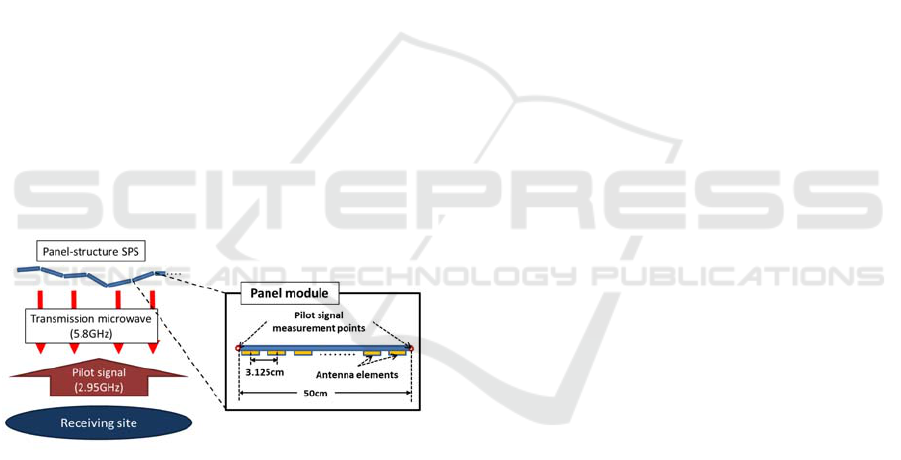
The panel-structure SPS is designed by Japanese
SPS committee. It consists of a large number of
power generation/transmission panel modules. This
type of SPS is suitable for mass production and easy
to maintenance. However, joints of the panel
modules are flexible and the panel-structure SPS is
difficult to maintain flatness of the transmission
antenna surface. In order to achieve the high beam
direction control accuracy, we have to correct the
output phase errors caused by the antenna surface
distortion.
Mitsubishi Heavy Industry’s SPS research group
proposed new beam correction methods which is
called a PAC (Position and Angle Collection)
method. The PAC method is one of the beam
correction methods for the panel-structure SPS. In
the PAC method, we measure phases of a pilot
signal, which was sent from a power receiving site
on the Earth, on every panel module. We estimate
the panel module positions by using the
measurement phases. Then, considering the panel
module positions, we correct the output phases of
pilot signal.
Fig. 6 Schematic Diagram of a SPS 1D Array
Model.
In Kyoto University, we simulated the PAC
method by a 1D array model shown in Figure 6.
Taking account of the SPS system, we set these
parameters. At first, we simulated the accuracy of
the PAC method. From the simulations, the pilot
signal measurement points have to be put on the
both ends of each panel module in order to achieve
the high beam direction control accuracy. However,
the spacing of two measurement points is much
longer than the half wavelength of the pilot signal
and ambiguities occur in the panel position
estimation method. Because of the ambiguities, we
can correct the output phase errors only when the
panel module gradients are in the range of -5 degrees
to 5 degrees. Thus, we propose an improved panel
position estimation method. By using this estimation
method, we can use the PAC method even if the
panel module gradients are in the range from -50
degrees to 50 degrees(Ishikawa, 2012).
4 CONCLUSIONS
There is no experimental satellite project for the SPS
in the world. Based on the developments of the new
phased array for the MPT, we hope the first
experimental satellite will be launched in Japan.
REFERENCES
Basic plan for space policy1, 2009,
http://www.kantei.go.jp/jp/singi/utyuu/basic_pla
n.pdf
Basic plan for space policy2, 2009,
http://www.kantei.go.jp/jp/singi/utyuu/keikaku/p
amph_en.pdf
Fuse, Y., T. Saito, S. Mihara, K. Ijichi, K. Namura, Y.
Honma, T. Sasaki, Y. Ozawa, E. Fujiwara, and T.
Fujiwara, “Outline and Progress of the Japanese
Microwave Energy Transmission Program for SSPS”,
Proc. of 2011 IEEE MTT-S International Microwave
Workshop Series on Innovative Wireless Power
Transmission: Technologies, Systems, and
Applications (IMWS-IWPT2011), pp.47-50, 2011
Homma, Y., T. Sasaki, K. Namura, F. Sameshima, T.
Ishikawa, H. Sumino and N. Shinohara, “New Phased
Array and Rectenna Array Systems for Microwave
Power Transmission Research”, Proc. of 2011 IEEE
MTT-S International Microwave Workshop Series on
Innovative Wireless Power Transmission:
Technologies, Systems, and Applications (IMWS-
IWPT2011), pp.59-62, 2011
Yamanaka, K., Y. Tuyama, H. Ohtsuka, S. Chaki, M.
Nakayama, and Y. Hirano, “Internally-matched GaN
HEMT High Efficiency Power Amplifier for Space
Solar Power Stations”, Proc. of Asia-Pacific
Microwave Conference 2010, pp.119-122, 2010
Ishikawa, I., and N. Shinohara, “Study on Microwave
Power Beam Correction Method with Deployment
System for Panel Structure SPS”, Proc. of 2012 IEEE
MTT-S International Microwave Workshop Series on
Innovative Wireless Power Transmission:
Technologies, Systems, and Applications (IMWS-
IWPT2012), pp.25-28, 2012
First International Conference on Telecommunications and Remote Sensing
22

BRIEF BIOGRAPHY
Naoki Shinohara received the B.E. degree in
electronic engineering, the M.E. and Ph.D (Eng.)
degrees in electrical engineering from Kyoto
University, Japan, in 1991, 1993 and 1996,
respectively. He was a research associate in the
Radio Atmospheric Science Center, Kyoto
University from 1998. He was a research associate
of the Radio Science Center for Space and
Atmosphere, Kyoto University by recognizing the
Radio Atmospheric Science Center from 2000, and
there he was an associate professor since 2001. he
was an associate professor in Research Institute for
Sustainable Humanosphere, Kyoto University by
recognizing the Radio Science Center for Space and
Atmosphere since 2004. From 2010, he has been a
professor in Research Institute for Sustainable
Humanosphere, Kyoto University. He has been
engaged in research on Solar Power Station/Satellite
and Microwave Power Transmission system. He is a
member of the IEEE, URSI, the Institute of
Electronics, Information and Communication
Engineers (IEICE) and the Institute of Electrical
Engineers of Japan (IEEJ).
Recent SPS Projects in Japan
23
