
Task-based Method for Designing Underactuated Elastic Mechanisms
Shoichiro Kamada
1
, Youngwoo Kim
1
and Goro Obinata
2
1
Graduate School of Engineering, Nagoya University, Nagoya, Japan
2
EcoTopia Science Institute, Nagoya University, Nagoya, Japan
Keywords: Underactuated Mechanism, Task-based Design, Principal Component Analysis, Elastic Element.
Abstract: In this paper, we introduce a task-based method for designing underactuated mechanisms which actuators
are linked with the joints via elastic elements. We consider multi-joint mechanisms that contain fewer
independent actuators than the joints. The elastic elements work as convertors from the displacement of the
actuators to the joint torques of the mechanisms. In our method, we analyze the joint motions of the
mechanisms during the completion of each task and the level of participation of each joint for few specific
tasks. The results of this study can be used for the synthesis of dedicated underactuated mechanisms that can
operate in a low task coordinate space and for the systematic design of underactuated mechanisms.
1 INTRODUCTION
The design of robot mechanisms has often been
inspired by the structure and functioning of the
human body. Such an approach in designing robot
hands leads to the synthesis of mechanisms that can
handle the objects more dexterously; however, the
designing of robot hands with a large number of
joints by mimicking the human structure often
becomes very complicated because of the necessity
of many actuators. While human muscles can
generate very high energy per unit weight, electrical
motors do not have high power-to-weight ratio. This
leads to serious design difficulties and the designed
robot hands becoming large, heavy and less
powerful.
Various studies show that specific human
movement tasks can be expressed by only a small
number of variables. Kim et al. (2011) confirmed
that only four to five principal components are
sufficient for achieving human walking patterns on a
smooth surface. A study of human hand motions
proved that a relatively small number of principal
components are engaged during the completion of
specific motions (Santello et al., 1998).
It is often suggested that hand prostheses and
robot grippers must possess a kinematic structure
that is similar to those of the natural human hand
that allows grasping or pinching of various objects
of different sizes and forms. Anthropomorphic hands
with a large number of joints are highly dexterous,
but the independent joint control requires a large
number of actuators. As a solution to the problem,
many design concepts of robotic hands have been
introduced with fewer actuators than degree-of-
freedom (DoF) in the hand mechanisms. For an
example in such concepts, one actuator is connected
with several joints and operates them simultaneously.
In this research field such mechanisms are often
called “underactuated” mechanisms. In our previous
research we already proposed a task-based method
for underactuated mechanisms in a systematic way
(Kamada et al., 2012). The method was based on the
analysis of the set of predefined tasks that should be
performed by the new robot hand, which the analysis
leads to the approximated motion trajectories with
fewer independent variables than the variables for
the exact achievement of the tasks. If such
approximation is allowed, we can design a robot
hand for the predefined tasks with a specific type of
device which is called linear dependent drive (LDD).
The approach allowed the synthesis of hands with a
simple structure that include fewer actuators than
joints and that possess high functionality and precise
motions for the named set of tasks. Generally, the
synthesized underactuated mechanisms can achieve
only the approximated motions to the exact ones of
mechanisms with the same kinematic structure and
independently controlled joints. To cope with such
deterioration on the accuracy of the motion
trajectories, Birglen et al. (2004) and Dollar et al.
(2007) introduced an approach that uses elastic
383
Kamada S., Kim Y. and Obinata G..
Task-based Method for Designing Underactuated Elastic Mechanisms.
DOI: 10.5220/0004121503830387
In Proceedings of the 9th International Conference on Informatics in Control, Automation and Robotics (ICINCO-2012), pages 383-387
ISBN: 978-989-8565-22-8
Copyright
c
2012 SCITEPRESS (Science and Technology Publications, Lda.)
elements for connecting the output of actuator to the
joints in a simple robot hand. Such solution solves
the problem on motion trajectories; moreover, the
feature of self-adaptability to the object different
shapes can be also expected because of the
characteristics of the elastic elements. However, this
robot hand is single purpose; only hard gripping the
object is possible but other types of tasks, for
examples pinching and twisting, are impossible.
To extend the good feature of such elastic robot
hands for multi-purpose, we apply the task-based
design method suggested by Kamada et al. in 2012
to design dextrous robot hands which possess more
than one actuator with several elastic elements. We
propose an index to analyze the level of participation
of each joint for the named set of the given tasks.
The kinematic and elastic parameters of the designed
underactuated mechanism are determined by
minimizing the criterion. We have verified the
proposed method with few numerical design
examples and provide here some of the key results
that demonstrate its effectiveness.
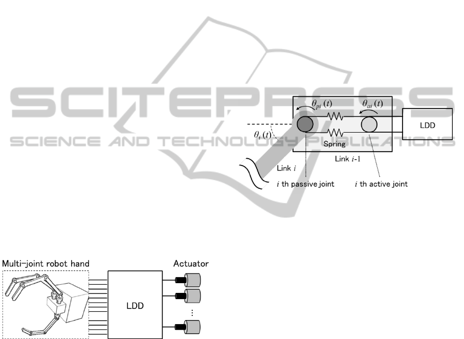
2 SYSTEM STRUCTURE
In the present study we consider gripper mechanisms
that consist of three components as represented in
Figure 1. The fingers of a multi-joint robot hand are
connected to a small set of actuators via Linear
Dependent Drives (LDDs).
Figure 1: Components of designed mechanisms.
The structure of the joint between the i th link and
the (i-1) th link is represented in Figure 2. Here,
θ
ai
(t) is the i th active joint angle, θ
pi
(t) is the i th
passive joint angle, θ
i
(t) is the i th actual joint angle
of the robot hand. Active joint angles are determined
by LDDs and displacements of actuators. LDDs are
mechanisms that transmit the displacements of the
actuators to the joints as follows:
cφθ
a
)()( tAt
(1)
Here, θ
a
(t)={θ
ai
(t)}R
n
is a vector of active joint
angles, AR
nr
is a constant matrix, φ(t)R
r
is a
vector of displacements of actuators (n>r), c R
n
is a
constant vector. The number of actuator r is smaller
than the number of the joints n. Passive joint angles
θ
p
(t)={θ
pi
(t)}R
n
are determined by the torques
which act on joints. The relation between passive
joint torques τ
p
(t)R
n
and passive joint angles is
given as follows:
)()( tKt
pp
θτ
(2)
Here, K=diag(k
1
, k
2
, … , k
n
) is a matrix of spring con
stants. k
i
(i=1, … , n) are positive values. If there is n
o external force, the actual joint angles of the hand θ
(t)={θ
i
(t)} R
n
equal to the active joint angles. With
some external forces, the actual joint angles of the h
and θ(t) are the sum of the active joint angles θ
a
(t) a
nd the passive joint angles θ
p
(t).
)()()( ttt
pa
θθθ
(3)
Figure 2: Connection between joints and LDD.
3 MECHANISM DESIGN
3.1 Principal Component Analysis
In this section we introduce a method for design of a
LDD. Initially, it is assumed that the mechanism is
fully actuated. Each joint of the mechanism is
connected with an independent actuator via a pair of
linear springs. From (2) and (3), joint angles of
active joints θ
a
(t) are represented as follows:
)()()(
1
tKtt
pa
τθθ
(4)
In our study, the joints of the hand and the actuators
are connected linearly via springs. The torques of the
active joints τ
a
(t)R
n
equal to the torques of the
passive joints τ
p
(t).
)()( tt
pa
ττ
(5)
From (4) and (5), the joint angles of the active joints
θ
a
(t) can be represented as follows:
)()()(
1
tKtt
aa
τθθ
(6)
ICINCO 2012 - 9th International Conference on Informatics in Control, Automation and Robotics
384
In equation (6), the active joint angles θ
a
(t) are the
sum of the actual joint angles of the hand θ(t) and
the weighted active joint torques τ
a
(t). The joint
angles θ(t) determine the positions/orientations of
the links of the hand. The active joint torques τ
a
(t)
determine expressing forces of the hand. If we
generate appropriate θ
a
(t) for the tasks, the hand
accomplish them. In our approach, the active joint
angles θ
a
(t) are analyzed and the information is used
for design of a LDD.
In the paper (Kamada et al. 2012), the design
method of a LDD based on Principal Component
Analysis (PCA) have been introduced. We follow
the method. PCA is a method which converts a
multivariable data set into a set of uncorrelated
variables called principal components by
orthonormal transformation. We apply PCA to the
joint angles data sets of the active joints for the
executed task motions. The relation between the
principal components p(t)R
n
and the active joint
angles θ
a
(t) is represented by the following equation:
a0a
θθp )()( tWt
(7)
Here, θ
a0
R
n
is the average of θ
a
(t), WR
nn
is the
translation matrix of PCA. We can calculate a
contribution rate for each principal component. Each
contribution rate indicates the proportion of the
variance of the principal component to the total
variance of the joint angles of the active joints θ
a
(t).
If we group all principal components into two
groups depending on their contribution rates, (7) can
be presented as follows:
a0a
l
h
θθ
p
p
p
)(
)(
)(
)( tW
W
W
t
t
t
l
h
(8)
where p
h
(t)R
r
is the r principal components with
higher contribution rates, p
l
(t)R
n-r
is the n-r
principal components with lower contribution rates,
W
h
R
rn
, W
l
R
(n-r)n
are the submatrices of W. The
reconstructed joint angles from p
h
(t) are given as
follows:
a0a
θpθ )()(
ˆ
1
tWt
T
h
(9)
where
)(
ˆ
t
a
θ
R
n
is the reconstructed active joint
angles. Since the relationship (9) corresponds to (1),
it can be used for calculation the matrix A and the
vector c. In this approach, the number of the
actuators equals to the dimension of p
1
(t).
Without external force, the fingers of the robot
hand generate approximated motion for the selected
tasks. If the contact points of the finger is similar to
the given task motions, the passive joint angles θ
p
(t)
take similar values to the given ones.
3.2 Design Method
In Section 3.1, the group of the principal
components with low contribution rates is excluded.
Therefore there is the reduction errors
(t) between
the original joint angles θ
a
(t) and the reconstructed
joint angles
)(
ˆ
t
a
θ
. The reduction errors
(t) can be
defined as follows:
)()()()(
ˆ
)( tIWWttt
nh
T
h
aaa
θθθΔ
(10)
If we change the link lengths or the spring constants,
the errors
(t) also change. We define the index J to
select the parameters. In this paper, ‖·‖ means the
Euclidean norm.
f
t
dttJ
0
2
)(Δ
(11)
Here, tasks are executed from t=0 to t=t
f
.
Minimizing J yields the optimal parameters for the
design.
4 DESIGN EXAMPLE
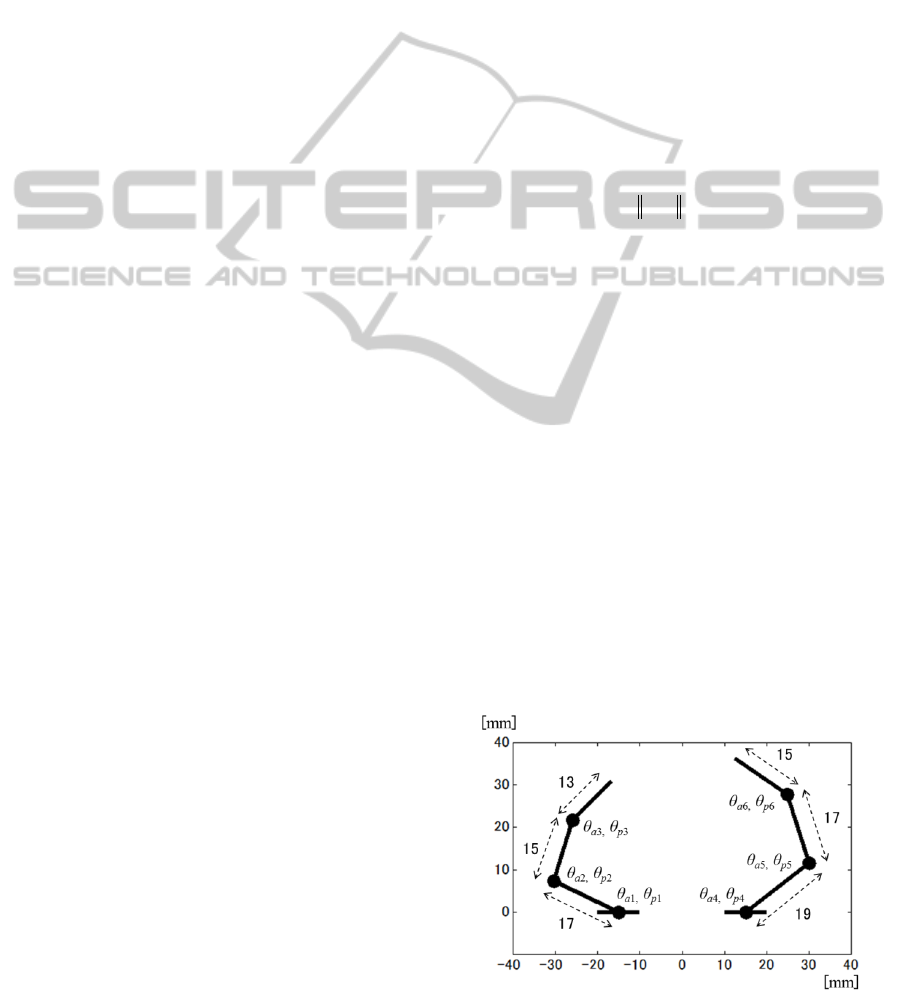
4.1 Structure of the Robot Hand
In this example, we consider a robot hand with two
fingers and six links (Figure 3). Here, θ
ai
are the
joint angles of the active joints, θ
pi
are the joint
angels of the passive joints (i = 1, …, 6). The spring
constants at each joint are given as
90,90,90
80,80,80
654
321
kkk
kkk
(12)
The units above are mN·m/rad. The hand has an
asymmetrical shape.
Figure 3: Shape of robot hand.
Task-based Method for Designing Underactuated Elastic Mechanisms
385
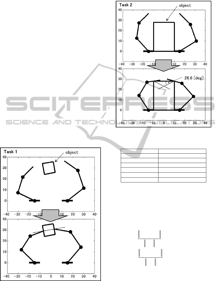
4.2 Given Tasks
We consider two tasks and design one robot hand
which can accomplish the given two tasks. The
dashed lines are applied forces. The motions for the
tasks are shown in Figure 4 and 5. Task 1 is to pinch
the target object with two fingers. The forces are
applied vertically to the both sides of the object by
the finger tips. The magnitudes of the forces are 0.5
N. Task 2 is to wrap the fingers around the target
object. The forces are applied to the object as
represented by Figure 5. The magnitudes of the
applied forces are 0.447 N. It is assumed that the
object is fastened on the floor plane. We analyzed
the motion for tasks as indicated in Figure 4 and 5.
We apply PCA to the joint angles of the active joints
while the gripper in Figure 3 executes the both tasks
in Figure 4 and 5. In Table 1, the contribution rates
of the principal components are shown. The
accumulate contribution rate of 2 major principal
components is 97.7%. If the size of the object
changes, the contribution rates also change.
However, the change of the accumulated
contribution rate of the two major principal
components is relatively small. In this chapter, we
design the mechanism with 2 actuators.
Figure 4: Motion for task 1.
Figure 5: Motion for task 2.
Table 1: Contribution rates.
Principal component
Contribution rate [%]
1
69.2
2
28.5
3
1.84
4
3.5610
-1
5
5.6710
-2
6
5.6310
-3
4.3 Motions of Designed Hand
The designed hand can apply forces to the target
objects as shown in Figure 6. We use the index of
(13) to evaluate the error between the force given as
the task motion and the force applied to the object
by the underactuated robot hand.
[%]100
[%]100
gr
argr
gl
algl
f
ff
f
ff
r
l
E
E
(13)
Here, f
gl
is the given force of the left finger, f
al
is the
actual force of the left finger, f
gr
is the given force of
the right finger, f
ar
is the actual force of the right
finger. In Table 2 and Table 3, we show the values
of E
l
and E
r
for each task. The results show that in
this simulation design example the forces to the
ICINCO 2012 - 9th International Conference on Informatics in Control, Automation and Robotics
386
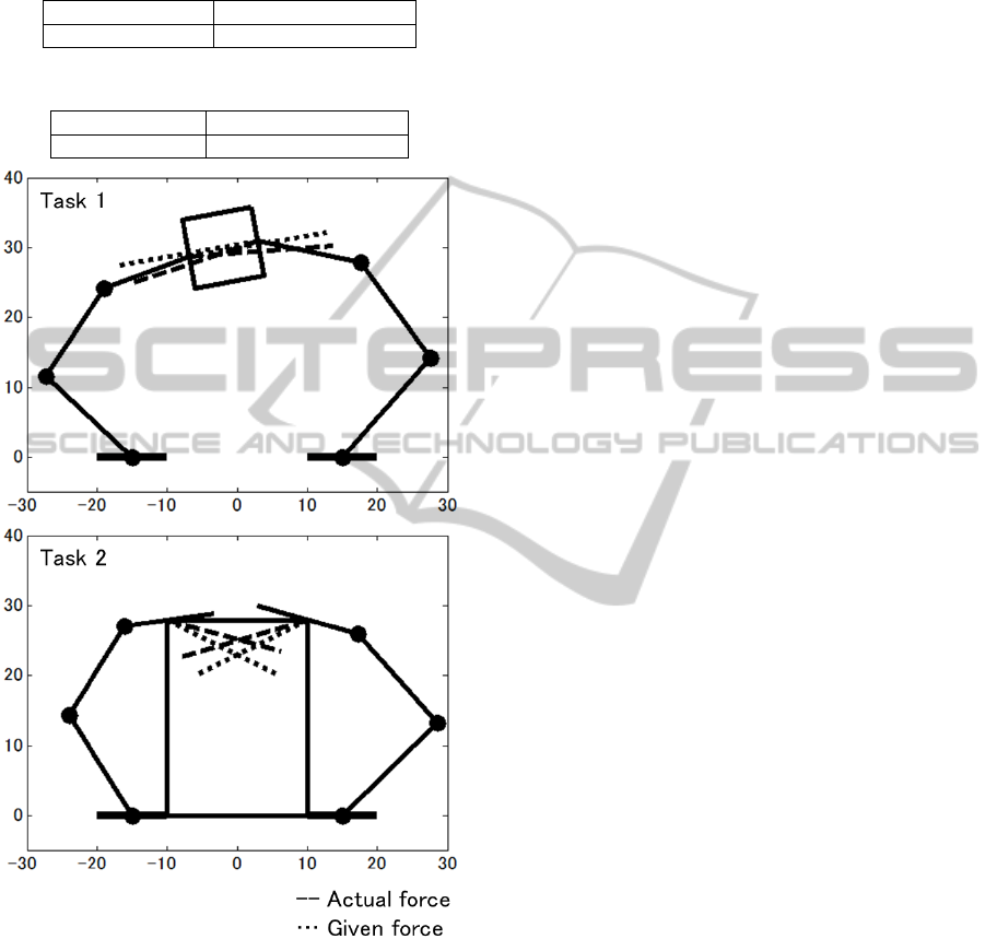
object are similar to the given ones and the
difference between them does not exceed 20 %.
Table 2: Error of force (Task1).
E
l
[%]
E
r
[%]
10.9
16.3
Table 3: Error of force (Task2).
E
l
[%]
E
r
[%]
19.7
18.9
Figure 6: Motions of designed hand.
5 CONCLUSIONS
We introduced a task-based method for design of
underactuated mechanisms attached elastic elements
between joints and actuators. The given tasks are
defined by the trajectories and the contact forces of
the links in the task coordinate space. At the
beginning, it is assumed that the given tasks are
performed by fully actuated mechanisms. We
analyze the joint motions of the mechanisms during
the completion of each task and synthesize dedicated
underactuated mechanisms. The proposed approach
allows the synthesis of underactuated mechanisms
that have fewer actuators than joints. Without
external force, the joint angles of the synthesized
mechanism are linearly dependent on the
displacements of the actuators. We presented an
example that shows promising results and potential
of the proposed method in various practical
applications.
ACKNOWLEDGEMENTS
We would like to thank to Dr. Dimitar Stefanov. He
gave us constructive comments and improved
English writing.
REFERENCES
Hirai, K., Hirose, M., Haikawa, Y., and Takenaka, T. 1998.
The Development of Honda Humanoid Robot, In Proc.
1998 IEEE International Conference on Robotics &
Automation, pp. 1321-1326.
Kawasaki, H., Komatsu, T., and Uchiyama, K. 2002.
Dexterous Anthropomorphic Robot Hand With
Distributed Tactile Sensor: Gifu Hand II, IEEE/ASME
Trans. on Mechatronics, Vol. 7, No. 3, pp. 296-303.
Kim, Y., Tagawa, Y., Obinata, G., and Hase, K. 2011.
Robust control of CPG-based 3D neuromusculo-
skeletal walking model, Biological Cybernetics, Vol.
105, Issue 3, pp. 269-282.
Santello, M., Flanders, M., and Soechting, J. F. 1998.
Postural Hand Synergies for Tool Use, The Journal of
Neuroscience, Vol. 18, No. 23, pp. 10105-10115.
Birglen, L., and Gosselin, C. M. 2004. Kinetostatic
Analysis of Underactuated Fingers, IEEE Trans. on
Robotics and Automation, Vol. 20, No. 2, pp. 211-221.
Dollar, A. M., and Howe, R. D. 2007. The SDM Hand as a
Prosthetic Terminal Device: A Feasibility Study, In
Proc. 2007 IEEE 10th International Conference on
Rehabilitation Robotics, pp. 978-983.
Kamada, S., Kim, Y., Obinata, G., and Stefanov, D., 2012.
Task-Based Method for Designing Underactuated
Mechanisms, International Journal of Advanced
Robotic Systems, Vol. 9, pp. 1-12.
Task-based Method for Designing Underactuated Elastic Mechanisms
387
