
Artificial Intelligence Methods in Reactive Navigation
of Mobile Robots Formation
Zenon Hendzel, Andrzej Burghardt and Marcin Szuster
Dept of Applied Mechanics and Robotics, Rzeszow University of Technology, 8 Powstancow Warszawy St., Rzeszow, Poland
Keywords:
Behavioural Control, Adaptive Critic Design, Robots Formation, Reactive Navigation, Neural Networks.
Abstract:
The article presents a hierarchical control system build using artificial intelligence methods, that generates
a trajectory of the wheeled mobile robots formation, and realises the tracking control task of all agents. The
hierarchical control system consists of a navigator, based on a conception of behavioural control signals coor-
dination, and individual tracking control systems for all mobile robots in the formation. The navigator realises
a sensor-based approach to the path planning process in the unknown 2-D environment with static obstacles.
The navigator presents a new approach to the behavioural control, where one Neural dynamic programming
algorithm generates the control signal for the complex behaviour, which is a composition of two individual be-
haviours: “goal-seeking”and “obstacle avoiding”. Influence of individual behaviours on the navigator control
signal depends on the environment conditions and changes fluently. On the basis of control signal generated
by the navigator are computed the desired collision-free trajectories for all robots in formation, realised by the
tracking control systems. Realisation of generated trajectories guarantees reaching the goal by selected point
of the robots formation with obstacles avoiding by all agents. Computer simulations have been conducted to
illustrate the process of path planning in the different environment conditions.
1 INTRODUCTION
The problem of large-size objects transport is difficult
to solve and expensivein realisation. It requires to use
suitably large transport facilities or a group of small
cooperating devices. The second conception seems to
be more adequate but is harder to apply. The trans-
porters cooperating in a formation in the large-size
load transportation task can be also useful after ful-
filling the task, but the cooperation of human opera-
tors is not always suitable and can lead to dangerous
situations. This problem can be solved by using au-
tonomous group of mobile robots, moving in a defi-
nite formation with precisely determined position of
individual agents in formation.
The tracking control task of the wheeled mobile
robot (WMR) is difficult because of its dynamics de-
scribed by the non-linear equations, and changeable
parameters during transportation tasks. The problem
of not known or changing parameters of the WMR
dynamics model in the tracking control task, is often
solved by using adaptive methods in the tracking con-
trol system, like modern Artificial inteligence (AI) al-
gorithms, especially neural networks (NNs). The sec-
ond problem is to coordinate the movement of all ag-
ents in the wheeled mobile robots formation (WMRF)
to successively complete the task. This type of prob-
lem can be solved by using virtual structure algo-
rithms (Egerstedt and Hu, 2001; Ogren and Leonard,
2003). The third problem concerns the conception
of sensor-based navigation in generating the trajec-
tory of the WMRF in the unknown environment with
static obstacles (Arkin, 1998; Fahimi, 2008; Maaref
and Barret, 2002; Millan, 1995). This task is often
solved by deriving inspiration from the wold of an-
imals in a form of behavioural methods of WMRF
control (Yamaguchi, 1997).
The development of AI methods, like NNs, al-
lowed to apply Bellman’s Dynamic Programming
(DP) idea in the form of Neural Dynamic Program-
ming (NDP) algorithms (Sutton and Barto, 1998;
Powell, 2007; Prokhorov and Wunsch, 1997; Si et al.,
2004), that proved to be very efficient in the control
tasks. In the article, the hierarchical control system
with NDP algorithms is presented. It consists of three
main layers: the highest is the navigator, that gener-
ates the desired trajectory of the WMRF, the middle
layer is the robots formation control system, that gen-
erates desired trajectories for all agents, and the low-
est layer consists of the tracking control systems for
466
Hendzel Z., Szuster M. and Burghardt A..
Artificial Intelligence Methods in Reactive Navigation of Mobile Robots Formation.
DOI: 10.5220/0004113404660473
In Proceedings of the 4th International Joint Conference on Computational Intelligence (NCTA-2012), pages 466-473
ISBN: 978-989-8565-33-4
Copyright
c
2012 SCITEPRESS (Science and Technology Publications, Lda.)
individual agents.
The results of scientific researches presented in
the article continuous authors’ earlier works related
to the tracking control of the WMR problem (Hendzel
and Szuster, 2010a; Hendzel and Szuster, 2010b), the
WMRF control (A. Burghardt and Giergiel, 2011)
and the trajectory generating process in the unknown
2D environment (Burghardt, 2004; Burghardt, 2008;
Hendzel, 2004; Hendzel and Szuster, 2011; Hendzel
and Szuster, 2012), where were used AI methods. The
article is organised in the following way: the first sec-
tion is an introduction to the WMRs control problem,
connected with the tracking control, the WMRF con-
trol and path planning. The second section contains
description of the WMR dynamics. The section three
presents hierarchical control system. Section four
contains results of numerical tests. The last section
summarises the article.
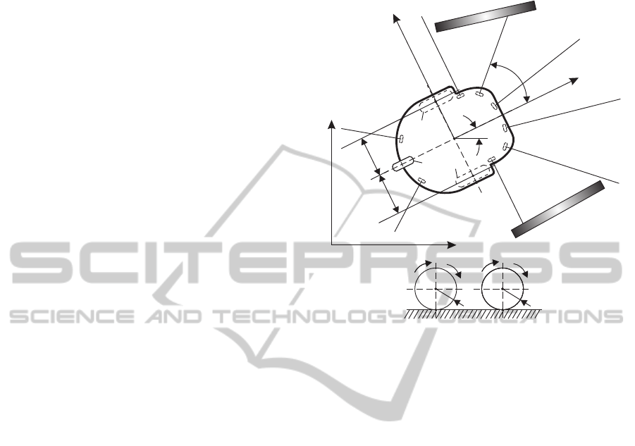
2 MODEL OF THE WHEELED
MOBILE ROBOT
The WMRF is composed of m = 3 WMRs Amigobot,
that form a virtual structure of a triangle. The WMR
Amigobot consists of two driving wheels, a frame and
a third castor wheel. It has eight ultrasonic range find-
ers s
1
, ..., s
8
for obstacles detection. Angles between
axes of ultrasonic range finders and the axis of the
frame of Amigobot are equal ω
1
= 144
◦
, ω
2
= 90
◦
,
ω
3
= 44
◦
, ω
4
= 12
◦
, ω
5
= −12
◦
, ω
6
= −44
◦
, ω
7
=
−90
◦
, ω
8
= −144
◦
, the range of individual range
finder measurements is equal to d
i
, i = 1,...,8, and
the maximal range d
mx
= 4 [m].
The discrete notation of the WMR dynamics was
derived using the Euler’s derivative approximation of
the model obtained by applying the Maggie’s math-
ematical formalism (Giergiel J., 2002; Giergiel and
Zylski, 2005), and takes the form
z
1{k+1}
= z
1{k}
+ z
2{k}
h ,
z
2{k+1}
= −M
−1
C
z
2{k}
z
2{k}
+ F
z
2{k}
+
+τ
d{k}
− u
{k}
h+ z
2{k}
,
(1)
where z
2{k}
=
z
2[1]{k}
,z
2[2]{k}
T
– the vector of dis-
crete angular velocities, M – the positive definite in-
ertia matrix, C
z
2{k}
z
2{k}
– the vector of Coriolis
and centrifugal forces, F
z
2{k}
– the vector of rolling
resistances, τ
d
– the vector of bounded disturbances,
u =
u
[1]
,u
[2]
T
– the vector of tracking control sig-
nals, h – the time discretization parameter, k – the in-
dex of iteration steps.
The movement of the WMR is analysed in xy
plane. The scheme of the WMR in the environment
with static obstacles is shown in fig. 1.
L
r
[1]
r
[2]
B
C
K
u
[1]
u
[2]
z
2[1]
z
2[2]
x
y
b
D
1
2
3
4
w
i
d
i
obstacle
obstacle
s
1
s
2
s
3
s
4
s
5
s
6
s
7
s
8
A
x
1
y
1
C
B
l
1
l
1
Figure 1: The wheeled mobile robot Amigobot scheme.
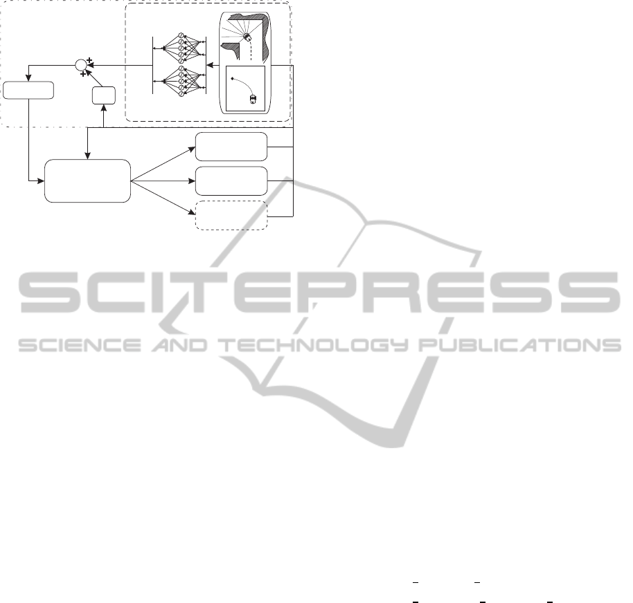
3 HIERARCHICAL CONTROL
SYSTEM
The proposed hierarchical control system is com-
posed of three main layers. The highest layer is the
navigator, that generates the desired trajectory of the
point M of the virtual structure. The middle layer is
the robots formation control system, that generates
desired trajectories for all agents. The lowest layer
consists of m tracking control systems for individual
agents. Scheme of the proposed hierarchical control
system is shown in fig. 2.
3.1 Navigation in the Unknown
Environment
The navigator consists of the discrete Action de-
pendant heuristic dynamic programming (ADHDP)
structures and the proportional (P) controller. The
ADHDP structures are adapted on-line using a rein-
forcement learning (RL) idea, that bases on the iter-
ative interaction with the environment. The NDP al-
gorithm searches for the optimal action to take. Per-
forming this action minimises the assumed cost func-
tion. The presented construction of the navigator is an
innovative approach to the trajectory generating pro-
cess, it uses the P regulator in the navigator to indicate
ArtificialIntelligenceMethodsinReactiveNavigationofMobileRobotsFormation
467
Obstacle Avoiding(OA)
+GoalSeeking(GS)
ADHDP
Kinematics
Trajectory
generator
P.
+
+
u
TA k{ }
u
T k{ }
u
TP k{ }
actor-critic
Proportional
regulator
Multi-robot
formation
control
.
q
dm k{ }
Trackingcontrol
robot1
Trackingcontrol
robot2
Trackingcontrol
robot2
Trackingcontrol
robot m
.
q
d2 k{ }
q
d1 k{ }
q
dM k{ }
q
1 k{ }
d
1 k{ }
q
2 k{ }
d
2 k{ }
q
m k{ }
d
m k{ }
q
i k{ }
d
i k{ }
Figure 2: Scheme of the control system for robots forma-
tion.
NDP structures adequate control signal at the begin-
ning of the adaptation process to limit exploration and
avoid the trial and error learning.
The navigator presents a new approach to the be-
havioural control, where one Neural dynamic pro-
gramming algorithm generates the control signal for
the complex behaviour, which is a composition of two
individual behaviours: “goal-seeking”(GS) and “ob-
stacle avoiding”(OA).
The overall navigator’s control signal u
T{k}
=
h
u
Tv{k}
,u
T
˙
β{k}
i
T
consists of the control signal u
Tv{k}
that controls the desired velocity of the point M of the
virtual structure, and the control signal u
T
˙
β{k}
, that
corresponds to the angular velocity of the WMRF’s
self-turn
˙
β
M
. The overall control signal u
T{k}
is a sum
of control signal generated by the actor-critic ADHDP
structures u
TA{k}
and the P regulator control signals
u
BP{k}
, according to equation
u
T{k}
= u
TA{k}
+ u
TP{k}
, (2)
where u
TP{k}
= K
T
e
T{k}
, K
T
- a fixed matrix of pro-
portional gains,
K
T
=
k
Tv
0 0
0 k
TO
k
TG
. (3)
and k
Tv
, k
TO
, k
TG
are fixed positive gains. The errors
of the trajectory generating layer are defined in the
form
e
v{k}
= f
d
∗
F{k}
f
l
G{k}
− v
A{k}
/v
∗
A
,
e
O{k}
= d
∗
R{k}
− d
∗
L{k}
,
e
G{k}
= ϕ
G{k}
− β
M{k}
,
(4)
where f (.) – a sigmoidal bipolar function, d
∗
F{k}
=
min
d
i[4]{k}
(s
i4
),d
i[5]{k}
(s
i5
)
/d
mx
– the normalised
distance to the obstacle in the front of the WMRF,
d
i[ j]{k}
– range of the j - th range finder of the
i-th WMR in the formation, l
G{k}
– the distance
of WMRF centre (point M) to the point G, v
M{k}
– a realised velocity of the point M of the vir-
tual structure, v
∗
M
– a maximal defined velocity of
the point M, d
L{k}
= min
d
1[3]{k}
(s
13
),d
2[3]{k}
(s
23
)
,
d
R{k}
= min
d
1[6]{k}
(s
16
), d
3[6]{k}
(s
36
)
, d
∗
L{k}
=
2
d
L{k}
/
d
L{k}
+ d
R{k}
− 0.5
– the normalised
distance to the obstacle on the left side of the WMRF,
d
∗
R{k}
= 2
d
R{k}
/
d
L{k}
+ d
R{k}
− 0.5
– the nor-
malised distance to the obstacle on the right, e
G{k}
–
the temporal angle between the x axis and the line p
G
,
β
M{ k}
– the temporal angle of the self-turn of the vir-
tual structure.
The main objective of the actor-critic structures in
ADHDP configuration is to generate control signals,
that minimises the value functions V
v{k}
and V
˙
β{k}
in
the form
V
v{k}
=
n
∑
k=0
γ
k
L
Cv{k}
,
V
˙
β
{
k}
=
n
∑
k=0
γ
k
L
C
˙
β{k}
,
(5)
where n – the last step of the finite discrete process, γ
– a discount factor (0 ≤ γ ≤ 1), L
Cv{k}
– a local cost in
step k for the first actor-critic structure, L
C
˙
β{k}
– a lo-
cal cost in step k for the second actor-critic structure
of the navigator.
ADHDP algorithm used in the proposed naviga-
tor does not require a mathematical model of the con-
trolled object or process in NNs adaptation laws.
The local costs L
Cv{k}
and L
C
˙
β{k}
were assumed in
the forms
L
Cv{k}
=
1
2
P
v
e
2
v{k}
+
1
2
R
v
u
2
Tv{k}
,
L
C
˙
β{k}
=
1
2
P
G
e
2
G{k}
+
1
2
P
O
e
2
O{k}
+
1
2
R
˙
β
u
2
T
˙
β{k}
,
(6)
where P
v
, P
G
, P
O
, R
v
, R
˙
β
– fixed, positive defined scal-
ing rates.
The navigator control signals were generated by
two actor-critic structures in ADHDP configuration.
ADHDP structure consists of:
• critic RVFL (Random Vector Functional Link)
NN, that estimates the suboptimal value functions
5, and generates signals
ˆ
V
v{k}
= W
T
Cv{k}
S
x
Cv{k}
,
ˆ
V
˙
β{k}
= W
T
C
˙
β{k}
S
x
C
˙
β{k}
,
(7)
where W
Cv{k}
, W
C
˙
β{k}
– vectors of critic NNs’
output-layer weights, S(.) – a vector of sigmoidal
IJCCI2012-InternationalJointConferenceonComputationalIntelligence
468
bipolar neurons activation functions, x
Cv{k}
,
x
C
˙
β{k}
– input vectors to the critic NNs. The in-
put vectors to the critic NNs consists of adequate
errors and control signals.
Critics’ weights are adapted by the back propa-
gation method of the Temporal Difference error
(Powell, 2007; Prokhorov and Wunsch, 1997; Si
et al., 2004).
• actor RVFL NNs, that generates the control law
u
TAv{k}
or u
TA
˙
β{k}
, according to equations
u
TAv{k}
= W
T
Av{k}
S
x
Av{k}
,
u
TA
˙
β{k}
= W
T
A
˙
β{k}
S
x
A
˙
β{k}
,
(8)
where W
Av{k}
, W
A
˙
β{k}
– vectors of actor NNs’
output-layer weights, x
Av{k}
, x
A
˙
β{k}
– input vec-
tors to the actor NNs.
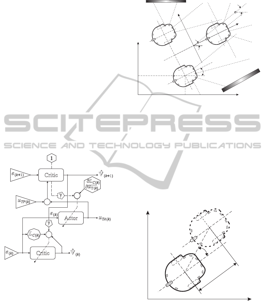
The general scheme of the NDP structure in AD-
HDP configuration used in the navigator is shown in
fig. 3, where e is the error vector.
+
+
+
-
1
+
¶u
T{ }k
Actor
Critic
Critic
e
{ 1}k+
L
C k{ }
u
TA k{ }
g
g
e
{ }k
V
{ 1}
^
k+
V
{ }
^
k
¶L
C k{ }
e
{ }k
u
TP k{ }
+
+
Figure 3: Scheme of the ADHDP structure.
The discrete navigator using ADHDP algorithms
was described in detail in (Hendzel and Szuster,
2012).
3.2 Control of the Robots in Formation
The WMRF control system uses the idea of the vir-
tual structure with the centre in point M(x
M{ k}
, y
M{ k}
),
and orientation defined by β
M{ k}
angle, shown in
fig. 4. Position and orientation of the virtual structure
change according to control signals of the navigator
(u
Tv{k}
and u
T
˙
β{k}
), that depend on the environment
conditions and assumed localisation of the goal.
p
G
y
G
G( , )x y
G G
l
G
x
y
x
m
y
m
A ( , )x y
m mm
A ( , )x y
2 22
A ( , )x y
1 11
x
1
y
1
b
m
M( , )x y
M M
b
M
d
F
d
L
d
R
obstacle
obstacle
Figure 4: The robots formation scheme.
Positions of characteristic points of the virtual
structure are traced by the WMRs points A in the way,
that the i-th WMR’s point A
i{k}
(x
i{k}
, y
i{k}
) is going
to achieve in the next iteration step the desired po-
sition A
di{k}
(x
di{k}
, y
di{k}
) computed on the basis of
the virtual structure position and orientation. The idea
of the WMRF control bases on generating trajectories
of point A of the individual WMRs. Determined tra-
jectories guarantee minimisation of errors δ
Li{k}
and
ψ
Li{k}
, what results in the trajectories, in which point
A
i
of the i-th WMR traces point A
di
of the virtual
structure. The idea of formation control is shown in
fig. 5.
x
y
A ( , )x y
i ii
y
Li
d
Li
A ( , )x y
di didi
Figure 5: Conception of robots formation control with er-
rors δ
Li{k}
and ψ
Li{k}
.
The location of the i-th WMR is defined by the
coordinates q
i{k}
=
x
i{k}
,y
i{k}
,β
i{k}
T
, where β
i{k}
is
an angle of the self turn of the i-th WMR’s frame.
We assumed the WMRF control signals in the
form
ArtificialIntelligenceMethodsinReactiveNavigationofMobileRobotsFormation
469
u
Fvi{k}
= k
F1
δ
Li{k}
cos
ψ
Li{k}
,
u
F
˙
βi{k}
= k
F1
sin
ψ
Li{k}
cos
ψ
Li{k}
+ k
F2
ψ
Li{k}
,
(9)
where k
F1
, k
F2
– positive constants. The presented
formation control system was presented in detail in
(A. Burghardt and Giergiel, 2011).
On the basis of the WMRF control signals u
Fvi{k}
and u
F
˙
βi{k}
the angular velocities of i-th WMR proper
wheels are calculated according to equation
z
di2[1]{k}
z
di2[2]{k}
=
1
r
v
∗
M
˙
β
∗
l
1
v
∗
M
−
˙
β
∗
l
1
u
Fvi{k}
u
F
˙
βi{k}
,
(10)
where
˙
β
∗
– a maximal defined angular velocity of the
self turn of the WMR frame, l
1
, r = r
[1]
= r
[2]
– the
lengths that derive from the WMR geometry.
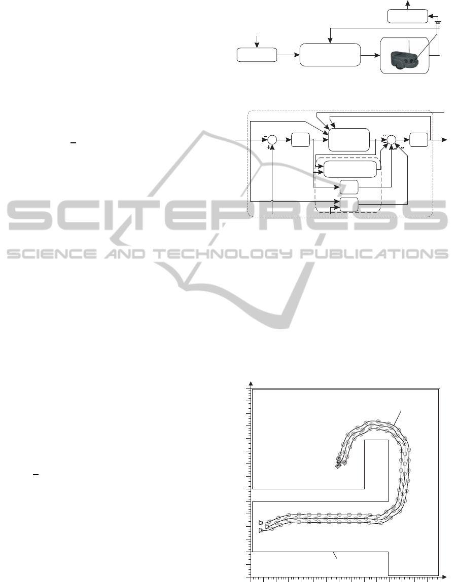
3.3 Tracking Control System
The discrete tracking control system realises trajec-
tory generated for an individual agent. It generates
control signals for the WMR driving systems. Re-
alisation of the tracking control signals allows the
point A of the WMR to keeps its position in the mov-
ing virtual structure of the WMRF. The tracking con-
trol system uses NDP algorithms in Dual heuristic
dynamic programming (DHP) configuration and was
described in detail in (Hendzel and Szuster, 2010b).
The overall tracking control signal consist of con-
trol signal generated by two NDP structures u
A{k}
=
u
A[1]{k}
,u
A[2]{k}
T
, the PD control signal u
PD{k}
, the
supervisory term control signal u
∗
S{k}
derived from the
Lyapunov stability theorem, and control signal u
E{k}
,
that derives from discretisation of the WMR’s model
in the closed system loop. The overall tracking con-
trol signal is assumed in the form
u
{
k}
=
1
h
M
n
−u
A{k}
+ u
∗
S{k}
− u
PD{k}
− u
E{k}
o
.
(11)
Scheme of the tracking control system for the i-th
WMR Amigobot in the formation is shown in fig. 6.
4 NUMERICAL EXPERIMENTS
RESULTS
In this section, for the sake of simplicity, all variables
are presented in a continuous domain of the time with
the time axis t on diagrams, not as the discrete vari-
ables, and there is not used index k, h = 0.01 [s].
Signalsfromrangefinders
Neuraltrackingcontrolsystem
e
{ }k
[ ]IL
s
{ }k
PD
-
Supervisoryterm
-
Wheeledmobile
robot Amigobot
1_
h
M
u
PD{ }k
u
S{ }
*
k
u
A k{ }
-
u
{ }k
-
+
z
{ }k
z
d k{ }
u
E
-
u
E{ }k
DHP
z
d k3{ }
actor-critic
Kinematics
q
di k{ }
Kinematics
q
i k{ }
d
i k{ }
u
{ }k
z
{ }k
Neuraltracking
controlsystem
z
d k{ }
z
d k3{ }
a)
b)
Figure 6: a) The tracking control system of the i-th mobile
robot, b) the neural tracking control system.
On the basis of the simulated range finders measure-
ments the proposed hierarchical control system gener-
ated the collision-free trajectory of the WMRF point
M, and the tracking control signals for all agents, that
allowed to realise the planed trajectory. The gener-
ated paths start in the point S, marked by the triangles
on the figure, and ends in the goal G, marked by the
X mark. In fig. 7 is shown the environment map with
the path of the points A of all WMRs of the formation
for the goal G(7.0, 9.0).
0 1 2 3 4 5 6 7 8 9 10 11 12 13 14 15
x [m]
0
1
2
3
4
5
6
7
8
9
10
11
12
13
14
15
y [m]
G (7.0, 9.0)
start
position
goal
path of the WMR
movement
environment map
Figure 7: The environment map with the path of the
wheeled mobile robots formation to the goal G(7.0, 9.0).
IJCCI2012-InternationalJointConferenceonComputationalIntelligence
470
Taking into account the behavioural conception of
the trajectory generating problem, the map of the en-
vironment was projected in the way, that the suc-
cessive path can not be generated using only one of
the behavioural control signals, for GS or OA task.
The proposed navigator generates control signals, that
make planning of the path in the complex task of ob-
stacle avoiding and goal seeking possible. The local-
isations of obstacles were computed on the basis of
simulated range finders readings, localisation and ori-
entation of the WMRs in the modelled environment.
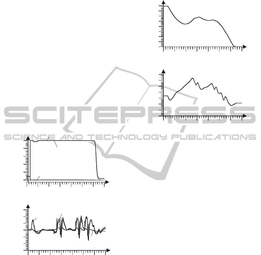
The overall trajectory generator control signals
u
Tv
and u
T
˙
β
, shown in fig. 8.a) and b), consists of
control signals generated by the NDP structures in
ADHDP configuration (u
TAv
, u
TA
˙
β
) and control sig-
nals of the P controller (u
TPv
, u
TP
˙
β
). The values of
control signals generated by the P controller are small
in a comparison with the ADHDP structures actors’
control signals u
TAv
and u
TA
˙
β
.
0 10 20 30 40 50 60 70
t [s]
0
0.2
0.4
0.6
0.8
1
u
Tv
, u
TAv
, u
TPv
a)
0 10 20 30 40 50 60 70
t [s]
-0.6
-0.4
-0.2
0
0.2
0.4
0.6
u
Tb
.
, u
T
Ab
.
, u
TPb
.
u
TA
b
.
b)
u
Tb
.
u
TP
b
.
u
TAv
u
Tv
u
TPv
Figure 8: a) The navigator control signals u
Tv
, u
TAv
and
u
TPv
, b) the navigator control signals u
T
˙
β
, u
TA
˙
β
and u
TP
˙
β
.
The distance to the goal G of the virtual struc-
ture M point is shown in fig. 9.a). It is consequently
reduced during the numerical test, to the value near
zero. The angle ψ
G
is shown in fig. 9.b).
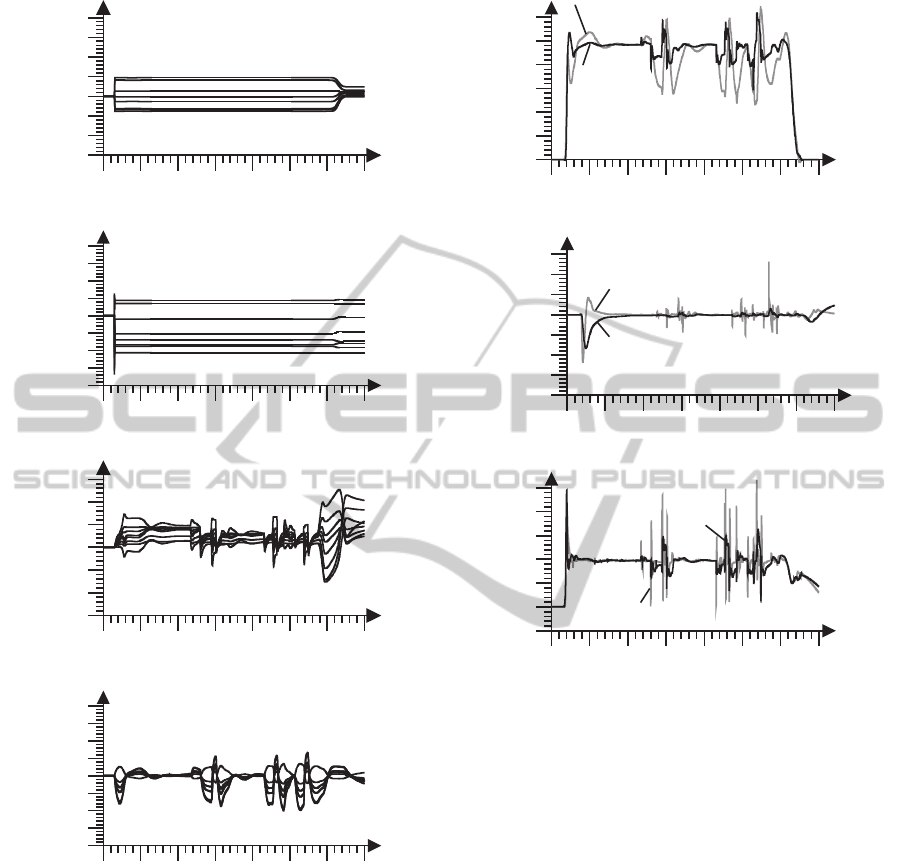
In fig. 10.a) and b) are shown values of the ac-
tor’s (W
TAv
) and the critic’s (W
TCv
) NN weights of
the ADHDP structure, that generates the navigator’s
control signal u
TAv
, that influences on the linear ve-
locity of the WMRF virtual structure. Values of the
actor’s (W
TA
˙
β
) and the critic’s (W
TC
˙
β
) NN weights
0 10 20 30 40 50 60 70
t [s]
0
1
2
3
4
5
6
7
8
l
G
[m]
a)
0 10 20 30 40 50 60 70
t [s]
-1
-0.5
0
0.5
1
1.5
2
2.5
G
[rad]
b)
y
Figure 9: a) The distance to the goal G, l
G
, b) the angle ψ
G
.
of the ADHDP structure, that generates the naviga-
tor’s control signal u
TA
˙
β
, are shown in fig. 10.c) and
d). This signal controls the angle of the WMRF vir-
tual structure turn. Weights of NNs are bounded and
converge to the fixed values.
On the basis of the overall control signals gener-
ated by the navigator,u
Tv
and u
T
˙
β
, taking into account
position of the point A of i-th agent in the WMRF, de-
sired angular velocities of the third WMR z
d32[1]
and
z
d32[2]
(fig. 11.a)) were computed. The desired trajec-
tory was realised, with the tracking errors shown in
fig. 11.b), using the tracking control system with the
overall tracking control signals u
3[1]
, u
3[2]
, shown in
fig. 11.c).
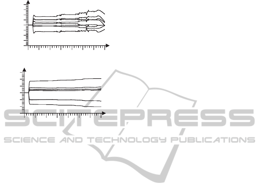
In fig. 12.a) and b) are shown values of the ac-
tor’s (W
A31
) and the critic’s (W
C31
) NN weights of
the DHP structure, that generates the tracking control
signal u
[1]
for the third agent in the WMRF. Weights
of NNs are bounded and converge to the fixed values.
5 SUMMARY
The proposed hierarchical control system generates
the trajectory for the WMRF and realises tracking
control of all agents. The generated trajectory is col-
lision free and allows to reach the goal by the selected
point of the WMRF. The sensor-based navigator was
builded using NDP algorithms in ADHDP configu-
ration. It is based on the behavioural control con-
ArtificialIntelligenceMethodsinReactiveNavigationofMobileRobotsFormation
471
0 10 20 30 40 50 60 70
t [s]
-0.4
-0.3
-0.2
-0.1
0
0.1
0.2
0.3
0.4
weights W
TCv
0 10 20 30 40 50 60 70
t [s]
-1
-0.75
-0.5
-0.25
0
0.25
0.5
0.75
1
weights W
TC
b
.
0 10 20 30 40 50 60 70
t [s]
-1.5
-1
-0.5
0
0.5
1
1.5
2
weights W
TAv
0 10 20 30 40 50 60 70
t [s]
-0.6
-0.4
-0.2
0
0.2
0.4
0.6
weights W
TA
b
.
b)
d)
a)
c)
Figure 10: a) Weights of the ADHDP actor 1 NN W
TAv
,
b) weights of the ADHDP critic 1 NN W
TCv
, c) weights of
the ADHDP actor 2 NN W
TA
˙
β
, d) weights of the ADHDP
critic 2 NN W
TC
˙
β
.
ception with use of only two individual behaviours:
“goal seeking”and “obstacle avoiding”, combined to
generate collision free trajectory that allows to reach
the goal. The new approach to the behaviour con-
trol used in the presented navigator allows to unite
two individual behavioural control systems for indi-
vidual behaviours into one structure. Appropriate po-
sition of the agent in the formation was ensured by
the virtual structure control algorithm, with control
0 10 20 30 40 50 60 70
t [s]
-1
0
1
2
3
4
5
u
3[1]
, u
3[2]
[Nm]
u
3[1]
u
3[2]
c)
a)
0 10 20 30 40 50 60 70
t [s]
0
1
2
3
4
5
6
z
d32[1]
, z
d32[2]
[rad/s]
z
d32[1]
z
d32[2]
b)
0 10 20 30 40 50 60 70
t [s]
-2
-1.5
-1
-0.5
0
0.5
1
1.5
e
31[1]
[rad], e
32[1]
[rad/s]
e
31[1]
e
32[1]
Figure 11: a) Desired
z
d32[1]
,z
d32[2]
angular veloci-
ties of the i-th agent, b) the tracking errors for the first
e
31[1]
,e
32[1]
, c) the overall tracking control signals u
3[1]
and u
3[2]
.
signals derived using the Lyapunov stability theory.
The trajectory generated for the individual agent was
realised using the tracking control system with DHP
structures. The proposed hierarchical control system
using AI methods, works on-line and does not require
the preliminary learning of NNs. Computer simula-
tions conducted to illustrate the path planning process
in the different environment conditions confirmed the
correctness of the assumed conception of the WMRF
hierarchical control. The selected point of the vir-
tual structure reaches the goal, while no one of agents
collides obstacles. The next step of the presented re-
searches will be verification of the proposed control
system using three Amigobot WMRs in the labora-
tory environment.
IJCCI2012-InternationalJointConferenceonComputationalIntelligence
472
0 10 20 30 40 50 60 70
t [s]
-0.4
-0.3
-0.2
-0.1
0
0.1
0.2
0.3
0.4
wagi W
A31
a)
0 10 20 30 40 50 60 70
t [s]
-12
-8
-4
0
4
8
12
wagi W
C31
b)
Figure 12: a) Weights of the DHP actor 1 NN W
A31
,
b) weights of the DHP critic 1 NN W
C31
.
ACKNOWLEDGEMENTS
This paper is supported by Polish Government under
Contract N N501 068838.
REFERENCES
A. Burghardt, T. B. and Giergiel, J. (2011). Control of
robots’ formation in unknown surroundings environ-
ment. In Dynamical Systems. Nonlinear dynamic and
control, Proc. of Conference on Dynamical Systems,
Theory and Applications. WPL.
Arkin, R. (1998). Behavior-Based Robotics. Intelligent
Robots and Autonomous Agents. MIT Press.
Burghardt, A. (2004). Behavioural control of wheeled
minirobot, (in polish). PAK, 11:26–29.
Burghardt, A. (2008). Proposal for a rapid prototyping envi-
ronment for algorithms intended for autonomous mo-
bile robot control. Mechanics and Mechanical Engi-
neering, 12:5–16.
Egerstedt, M. and Hu, X. (2001). Formation constrained
multi-agent control. IEEE Transactions on Robotics
and Automation, 17(6):947–951.
Fahimi, F. (2008). Autonomous Robots: Modeling, Path
Planning, and Control. Springer.
Giergiel, J. and Zylski, W. (2005). Description of motion of
a mobile robot by maggie’s equations. J. Theor. App.
Mech., 43:511–521.
Giergiel J., Hendzel Z., Z. W. (2002). Modeling and control
of wheeled mobile robots (in Polish). PWN.
Hendzel, Z. (2004). Fuzzy reactive control of wheeled mo-
bile robot. J. Theor. App. Mech., 42:503–517.
Hendzel, Z. and Szuster, M. (2010a). Discrete action depen-
dant heuristic dynamic programming in wheeled mo-
bile robot control. Solid State Phenomena, 164:419–
424.
Hendzel, Z. and Szuster, M. (2010b). Discrete model-based
adaptive critic designs in wheeled mobile robot con-
trol. In Proceedings of the 10th international con-
ference on Artifical intelligence and soft computing:
Part II, ICAISC’10, pages 264–271, Berlin, Heidel-
berg. Springer-Verlag.
Hendzel, Z. and Szuster, M. (2011). Neural dynamic pro-
gramming in behavioural control of wheeled mobile
robot (in polish). Acta Mechanica et Automatica,
5(1):28–36.
Hendzel, Z. and Szuster, M. (2012). Neural dynamic pro-
gramming in reactive navigation of wheeled mobile
robot. LNCS, 7268:450–457.
Maaref, H. and Barret, C. (2002). Sensor-based navigation
of a mobile robot in an indoor environment. Robotics
and Autonomous Systems, 38(1):1–18.
Millan, J. D. (1995). Reinforcement learning of goal-
directed obstacle-avoiding reaction strategies in an au-
tonomous mobile robot. Robotics and Autonomous
Systems, 15:237–246.
Ogren, P. and Leonard, N. (2003). Obstacle avoidance in
formation. Proceedings of 2003 ICRA.
Powell, W. B. (2007). Approximate Dynamic Program-
ming: Solving the Curses of Dimensionality (WileySe-
ries in Probability and Statistics). Wiley-Interscience.
Prokhorov, D. V. and Wunsch, D. C. (1997). Adaptive
critic designs. IEEE Transactions on Neural Net-
works, 8(5):997–1007.
Si, J., Barto, A. G., Powell, W. B., and Wunsch, D. (2004).
Handbook of Learning and Approximate Dynamic
Programming (IEEE Press Series on Computational
Intelligence). Wiley-IEEE Press.
Sutton, R. and Barto, A. (1998). Reinforcement Learning:
An Introduction. Adaptive Computation and Machine
Learning. MIT Press.
Yamaguchi, H. (1997). Adaptive formation control for dis-
tributed autonomous mobile robot groups. In Robotics
and Automation, 1997. Proceedings., 1997 IEEE In-
ternational Conference on, volume 3, pages 2300–
2305.
ArtificialIntelligenceMethodsinReactiveNavigationofMobileRobotsFormation
473
