
A Meta-Model for DEVS
Designed following Model Driven Engineering Specifications
Stéphane Garredu, Evelyne Vittori, Jean-François Santucci and Paul-Antoine Bisgambiglia
SPE-UMR 6134, Università di Corsica, FST Campus Grimaldi, Corte, France
Keywords: DEVS, MDE, MDA, MOF, UML, Meta-modeling, DEVS Interoperability, Model-to-Model
Transformations, Model-to-Text Transformations, OMG MTL.
Abstract: In this paper we give a state-of-art of DEVS components interoperability, and we propose a meta-model for
classic DEVS formalism, designed following a Model-Driven Engineering philosophy. After glancing at the
existing related works, we explain in a step-by-step way how our meta-model is built, starting from the
formal definition of DEVS formalism. As the hardest steps when defining a DEVS Platform-Independent
Model (PIM) are the definition of the states and the definition of the DEVS functions, we particularly focus
on those concepts and we propose a way to describe them in a simple and platform-independent way. UML
class diagrams were chosen to represent this meta-model. Not only can this meta-model be useful to
generate DEVS PIMs but it can also be seen as a powerful tool to improve interoperability between DEVS
models (and in a larger way discrete-event models, via model-to-model transformations) and to provide
automatic code generation towards DEVS simulators (model-to-text transformations). As this meta-model is
not a final version but rather a starting point, we tried to make it as modular and upgradable as possible.
1 INTRODUCTION
For over 30 years now, the Discrete Event system
Specification (DEVS) formalism has been used for
modeling and simulating both discrete-event
dynamic systems (and continuous systems) by a
growing enthusiast community of scientists all over
the world.
Describing a DEVS model in order to perform its
simulation can only be done if we resort to an
Object-Oriented programming Language (OOL),
tied to a particular DEVS simulation platform. Thus,
implementing a DEVS model with an OOL leads to
a loss of comprehensibility, a loss of precision and a
loss of interoperability.
The approach our team has been working on
aims to ease the modeling process and increase the
interoperability of DEVS models. From our point of
view, it can be done if the advantages of Model
Driven Engineering (MDE) methodology are applied
to modeling and simulation. An important part of
this approach is to allow the description of DEVS
models in a unified way, without considering the
platform in which the models will be simulated. To
stick to this philosophy, each DEVS model should
conform to the same pattern. This pattern should
provide all the necessary DEVS concepts in order to
create DEVS models in a unified way: such a pattern
is called a meta-model.
The purpose of this paper is to propose a meta-
model for DEVS. This meta-model is likely to be
enriched with new features: it is designed in a
modular way, and it is upgradable. For read-through
strength reasons, it is shown in this paper with a
well-known and understandable formalism: UML
class diagrams. It also has been fully implemented
within Eclipse Modeling Framework.
This paper starts with the background section:
we present the classic DEVS formalism, DEVS
modeling and simulation philosophy, and DEVS
components interoperability. We say a few words
about UML, MDE (and its particular form Model
Driven Architecture or MDA), we also focus on
related work about DEVS meta-modeling and give a
state-of-art of these approaches. We conclude by a
discussion about this related work. The second part
is dedicated to the process we followed to create our
DEVS meta-model. As much as possible, we try to
stick to the formal definition of DEVS formalism,
and we stress on the particular case of the DEVS
states. We present all the meta-classes involved in
the definition of our meta-model and we stress on
152
Garredu S., Vittori E., Santucci J. and Bisgambiglia P..
A Meta-Model for DEVS - Designed following Model Driven Engineering Specifications.
DOI: 10.5220/0004061501520157
In Proceedings of the 2nd International Conference on Simulation and Modeling Methodologies, Technologies and Applications (SIMULTECH-2012),
pages 152-157
ISBN: 978-989-8565-20-4
Copyright
c
2012 SCITEPRESS (Science and Technology Publications, Lda.)

the definition of states and functions. Finally, we
give a conclusion.
2 BACKGROUND
2.1 Classic DEVS Formalism
DEVS formalism was introduced in the seventies by
Pr. Zeigler, it is based on discrete events, and it
provides a framework with mathematical concepts
based on the sets theory and systems theory concepts
to describe the structure and the behaviour of a
system (Zeigler, 1989). DEVS knows two kinds of
models: the atomic models, which describe a
behavior, and the coupled models which describe a
hierarchy.
With DEVS, there is an explicit separation
between a model and its simulator: once a model is
defined, it is used to build a simulator (i.e. a device
able to execute the model’s instructions).
Now we present the two DEVS models: atomic
models and coupled models.
2.1.1 DEVS Atomic Models
The tiniest element in DEVS formalism is the
atomic model. It is specified as
AM = < X, Y, S, ta, δ
int
, δ
ext
, λ >
where
- X = {(p,v)|p
InputPorts, vX
p
} is the input events
set, through which external events are received;
InputPorts is the set of input ports and X
p
is the set
of possible values for those input ports
- Y = {(p,v)|p
OutputPorts, vY
p
} is the output
events set, through which external events are sent;
OutputPorts is the set of output ports and X
p
is the
set of possible values for those output ports
- S is the states set of the system;
- ta: S → R
0
+
+∞ is the time advance function (or
lifespan of a state);
- δ
int
: S → S is the internal transition function;
- δ
ext
: Q × X → S with Q = {(s,e)/sS, e[0,ta(s)]} is
the external transition function;
- λ: S → Y, with Y = {(p,v)|p
OutputPorts, vY
p
} is
the output function;
The simplest transition is called the internal
transition, it behaves as follows: at a given moment,
a system is in a state sS. Unless an external event
occurs on an input port, the system remains in the s
state for a duration defined by ta(s). When ta(s)
expires, the model sends the value defined by λ(s) on
an output port y
Y
, and then it changes to a new
state defined by δ
int
(s). Such a transition, which
occurs because of the expiration of ta(s), is an
internal transition.
The other transition type is called the external
transition, because it is triggered by an external
event. In this case, it is the δ
ext
(s,e,x) function which
defines which state is the next one (s is the current
state, e is the elapsed time since the last transition,
and xX
is the event received).
In both cases, the system is now in a new state s’
for a new duration d’ = ta(s’) and the algorithm
restarts.
S
ta
X
Y
δ
ext
δ
int
λ
Figure 1: A DEVS atomic model.
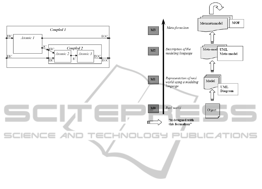
2.1.2 DEVS Coupled Models
A coupled model is composed of at least one
submodel (atomic or coupled). It is formally defined
by
MC = <X, Y, D, {Md|d
D}, EIC, EOC, IC, select>
Where
- X = {(p,v)|p
InputPorts, vX
p
} is the input events
set, through which external events are received;
InputPorts is the set of input ports and X
p
is the set
of possible values for those input ports
- Y = {(p,v)|p
OutputPorts, vY
p
} is the output
events set, through which external events are sent;
OutputPorts is the set of output ports and X
p
is the
set of possible values for those output ports
- D is the set of component names, d
D
- M
d
is a DEVS model (either atomic or coupled)
- EIC is the set of external input couplings;
- EOC is the set of external output couplings;
- IC is the set of internal couplings;
- select is the tiebreaker function
Figure 2 illustrates an example of a coupled model.
2.1.3 DEVS Simulators
Several simulators for DEVS have been
implemented.
They are built with various OOL languages and
even for those which use the same language, the
simulations algorithms are different. Among them
AMeta-ModelforDEVS-DesignedfollowingModelDrivenEngineeringSpecifications
153
we can quote CD++ (Wainer, 2002), a framework
which uses C++, JDEVS (Filippi et al., 2004) and
DEVSJAVA (ACIMS 2012) which both use JAVA,
PythonDEVS (Bolduc et al., 2002) which is written
in Python.
Figure 2: A DEVS coupled model.
2.1.4 DEVS Components Interoperability
The fact of implementing a DEVS model highly
reduces its interoperability.
To solve this, two major kinds of solutions have
been used. The first one aims to increase the
interoperability in a model-centered way, while the
second one aims to increase the interoperability from
the simulator’s point of view, using standard
messages between at least two different simulation
platforms where different models are defined. For
instance, (Seo, 2009) is a simulator-oriented
proposal for a better DEVS simulators
interoperability using SOA.
An exhaustive overview of all those different
solutions is presented in (Touraille et al., 2009).
As our approach is part of the first kind of
solutions, we will only focus on the existing work
which belongs to DEVS models interoperability.
2.2 Software Engineering Background
2.2.1 UML
Unified Modeling Language (UML) is a graphical
set of modeling formalisms: it provides a toolkit
which enables one to model the structural aspects of
a system as well as its behavior (Booch et al., 1998).
UML is owned by the Object Management
Group, and its current version is UML 2.4.1 (OMG,
2011). Its main advantage is that it is considered as a
standard formalism by a large worldwide
community of users.
2.2.2 UML and Meta-Levels
A UML model, for instance a UML class diagram, is
an abstraction of a system from the real world
located at the lowest abstraction level: M0. Such an
abstraction takes place at a higher level: M1. It is
defined by its meta-model at, once more, a higher
level: M2.
Figure 3: UML and the “meta” levels.
This meta-model describes the elements that can be
used to design the model and their relationships with
each other. Such a description is defined at a higher
level by Meta Object Facility (MOF), a language
used to describe other languages. This level is M3.
MOF is defined on itself, i.e. it is described in MOF
terms. Hence, there is no level higher than M3
(Figure 3).
2.2.3 MDE and MDA
Model Driven Engineering is a software
development methodology which focuses on
creating and exploiting domain models. MDE is a
generic approach, and its most famous
implementation is Model Driven Architecture,
owned by the OMG.
MDA (Model Driven Architecture) (OMG,
2001) is a software design approach initiated by the
OMG in 2001 to introduce a new way of
development based upon models rather than code.
MDA defines a set of guidelines for defining
models at different abstraction levels, starting from
Computational Independent Models (CIMs) to
platform independent models (PIMs), then from
PIMs to platform specific models (PSMs) which are
tied to a particular technology (i.e. platform). The
translation from one PIM to one or several PSMs is
to be performed automatically by using
transformation tools. MDA also enables
SIMULTECH2012-2ndInternationalConferenceonSimulationandModelingMethodologies,Technologiesand
Applications
154

transforming a PSM into source code. The
advantage of such an approach is the great
reusability of models.
OMG provides a set of standards dedicated to
this approach. Although UML was at the beginning
the basis of the OMG works on MDA, it is now
Meta-Object Facility (MOF) which appears to be the
most basic standard. The MOF equivalent in EMF is
Ecore.
2.3 Work related to DEVS
Meta-Modeling
A DEVS meta-model must allow the description of
DEVS atomic and coupled PIMs in terms of DEVS
formalism. The related work about DEVS meta-
modeling can be characterized by the formalism
used to define the meta-model.
Many approaches use XML to specify the DEVS
basic elements, such as (Mittal et al., 2007) which
can be considered as a “hybrid” approach as it uses
SOA in order to perform the simulation. DTDs are
used to describe the structure of a DEVS component.
A DEVS framework named SimStudio uses a
similar specification language named DML
(Touraille et al., 2010). It also has its own simulation
engine called DEVS-MS. In this approach, the XML
schema (and not the DTD) gives the structure of a
DEVS component.
A DEVS meta-model was also specified using
Entity-Relationship diagrams, the meta-meta-
formalism used by AToM
3
(Posse et al., 2003).
The main difficulty that remains is to specify the
behaviour of the models: to do so, the previous
approaches often use object-oriented code (with a
loss of the platform-independent aspect) or hybrid
code (a mix between generic code and object-
oriented code.
3 A META-MODEL FOR DEVS
The goal of our approach is to make a proposal for a
DEVS meta-model. In order to be fully compliant
with MDE and in particular MDA philosophy, all
the models generated from this single entry point are
platform-independent. We chose UML class-
diagrams to represent the meta-classes of our meta-
model, and we implemented it within EMF. The
theoretical aspects of our approach are presented in a
more detailed way in (Garredu et al., 2011).
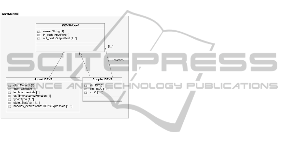
3.1.1 Basic Hierarchy
Every DEVS model must be given a name.
Moreover, it can either be atomic or coupled. As a
consequence, there must exist an abstract meta-class
DEVSModel from which two sub-classes
(AtomicDEVS and CoupledDEVS) inherit. A
coupled DEVS model contains at least one DEVS
model. Such a basic hierarchy will be refined and
presented in the DEVSModel package.
3.1.2 Dealing with Types
Types are defined differently following the object-
oriented languages. So, our meta-model must be able
to handle types, in a generic way. Types will be
useful. We chose to represent only 4 basic types
(StringType, IntegerType, CharType, BooleanType)
but this can be easily extended. The types inherit
from the Type abstract meta-class.
3.1.3 Representing the States
In a formal point of view, a DEVS atomic model is
composed of a finite set of its possible states S
linked by deterministic transitions. Those states are
distinct values; it implies that the fact of changing a
state may lead to the creation of another state.
This is not a problem for the systems of which
the states are known (and can be enumerated) but it
becomes one when we have to deal with states
which take their values in infinite sets, for instance
[0;1]R.
To solve this problem, we chose to represent a
state by what we call a state variable. It takes a new
value when the state changes (i.e. each new state
change will lead to a change of the value of the state
variable).
Therefore, only a state variable is used to
represent a collection of states which belong to the
“same kind”. A state variable must be named, and
must be typed. It can also be affected a literal value.
3.1.4 The Ports
Each port must be named, and also must be typed in
order to send or receive information. A port can be
an input port, or an output port. Port is an abstract
meta-class from which inherit the two meta-classes
InputPort and OutputPort.
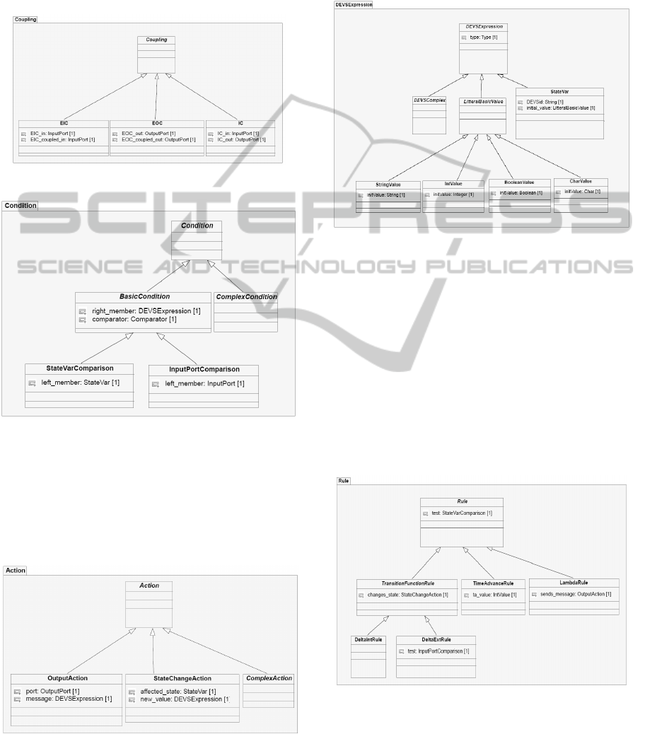
3.1.5 The Coupling Functions
Once we know how to represent a port, we easily
can write the meta-classes which describe the
coupling functions (in the coupled models). Some
AMeta-ModelforDEVS-DesignedfollowingModelDrivenEngineeringSpecifications
155
information cannot be directly specified here (for
instance, the fact that EIC involves 2 sub-models)
but it can be using OCL constraints. Figure 4
represents the Coupling package. As usual, there is
an abstract class (Coupling) from which inherit 3
sub-classes: EIC, EOC, IC.
Figure 4: The Coupling package.
Figure 5: The Condition package.
A condition (see Figure 5) is described by a test: a
left member, a comparator, and a right member.
It can be a test on an input port (in the case of an
external transition function) or on a state variable (in
every DEVS atomic function, there is a test on a
state variable).
Figure 6: The Action package.
An action (figure 6), in fact the description of an
action, can be an output action (on a port), or a state
change action (in the case of a transition function).
3.1.6 DEVS Expressions
Figure 7: The DEVSExpression package.
We chose to describe state variables and types, and
they can be included in a larger set which is called
DEVSExpression. It is one of the basis of our meta-
model. As a StateVar is a DEVSExpression, a
LitteralBasicValue is also a simpler one, in fact the
simplest one because it is composed of a unique
typed value. We built this package (see Figure 7) in
a modular way, in order to facilitate its modification
by enriching it with other sub-classes.
DEVSComplex is a good starting point to do so.
3.1.7 DEVS Rules
Figure 8: The Rule package.
In spite of the differences between the DEVS
functions, we can notice that every function can
describe a test, an action on a variable, a message.
Those descriptions follow a sort of pattern which is
SIMULTECH2012-2ndInternationalConferenceonSimulationandModelingMethodologies,Technologiesand
Applications
156
often the same: a set of enumerations. Those
enumerations are DEVS Rules. The purpose of a rule
is to represent a set of operations on specific
elements.
A rule is always composed of a condition and an
action. The Rules package (Figure 8) purpose is to
enable the description of simple rules often used in
DEVS atomic models. We finally present the core of
our meta-model, the DEVS-Models package (Figure
9). It takes into account all we said before, putting
all together.
Figure 9: The DEVSModel package.
4 CONCLUSIONS
We presented in this paper a state-of-art about
DEVS models interoperability and proposed the first
fully platform-independent meta-model for DEVS
formalism. Although this meta-model only allows
specifying simple functions, it is consistent with
classical DEVS formalism.
This meta-model has been implemented within
the Eclipse Modeling Framework and used in a
MDA approach to perform code generation. Models
were designed in EMF, then with Model-To-Text
transformations, Python code was generated. This
will be presented in another paper.
The meta-model’s modular features will help us
to improve it; the next step in our work is the
definition of complex expressions.
RFERENCES
ACIMS, DEVSJAVA, http://www.acims.arizona.edu,2012
J.-S. Bolduc and H. Vangheluwe, A modeling and
simulation package for classic hierarchical DEVS.
Internal document for the Modelling, Simulation and
Design Lab (MSDL), School of Computer Science,
McGill University, 2002.
G. Booch, J. Rumbaugh, and I. Jacobson. “The unified
Modeling Language User Guide”. Addison-Wesley,
1998.
J.-B. Filippi and P. Bisgambiglia, JDEVS: “An
implementation of a DEVS based on formal
framework for environmental modelling” Original
Research Article Environmental Modelling &
vSoftware, Volume 19, Issue 3, March 2004, Pages
261-274
S. Garredu, E. Vittori, J.-F. Santucci, D. Urbani, “A
methodology to specify DEVS domain specific
profiles and create profile-based models”, IEEE-IRI
2011, 3-5 Aug. 2011, Las Vegas, NV, U.S.A., pp. 353 -
359
S. Mittal, J. L. R. Martín., B.P. Zeigler « DEVSML:
automating DEVS execution over SOA towards
transparent simulators », Proceedings of the 2007
ACM Spring Simulation Multiconference, March 25-
29, 2007, Norfolk, VA, USA, Vol. 2, pp. 287-295.
OMG 2011. Unified Modeling Language: Superstructure
and infrastructure, version 2.4.1, August 2011
http://www.omg.org/spec/UML/2.4.1/
OMG 2001. Model Driven Architecture homepage
http://www.omg.org/mda/
Posse E., Bolduc J.-S., « Generation of DEVS Modelling
& Simulation Environments », Proceedings of the
2003 SCS Summer Computer Simulation Conference,
July 2003, Montréal, Canada, pp. 295-300.
C. Seo, "Interoperability between DEVS Simulators using
Service Oriented Architecture and DEVS
Namespace", Ph.D. Dissertation, Electrical and
Computer Engineering Dept., University of Arizona,
Spring 2009
L.Touraille, M. K. Traoré, D. Hill, "On the interoperability
of DEVS components: On-Line vs. Off-Line
Strategies.", 2009, UMR CNRS 6158, LIMOS/RR-09-
04, 13 p.
L.Touraille, M.K. Traoré, D. Hill, « SimStudio : une
Infrastructure pour la Modélisation, la Simulation et
l’Analyse de Systèmes Dynamiques Complexes »,
UMR CNRS 6158, LIMOS/RR-10-13, 2010, 12 p.
(2010)
G. Wainer, “CD++: a toolkit to define discrete event
models”. Software, Practice and Experience. Vol.32,
No.3. pp. 1261-1306. November 2002
B.P. Zeigler, 1989. "DEVS Representation of Dynamical
System", in Proceedings of the IEEE, Vol.77, pp.72-80
AMeta-ModelforDEVS-DesignedfollowingModelDrivenEngineeringSpecifications
157
