
A Distributed Architecture for Remote Service Discovery
in Pervasive Computing
∗
Farzad Salehi
1
, Stefan D. Bruda
1
, Yasir Malik
2
and Bessam Abdulrazak
2
1
Bishop’s University, Sherbrooke, QC J1M 1Z7, Canada
2
Universit´e de Sherbrooke, Sherbrooke, QC J1K 2R1, Canada
Keywords:
Service Discovery, Peer to Peer, Pervasive Computing, UPnP, Gnutella.
Abstract:
Service discovery is very important in realizing the concept of pervasive computing. Consequently, service
discovery protocols must be able to work in the heterogeneous environment offered by pervasive computing.
Remote service discovery in particular has not been properly achieved so far. In an attempt to remedy this we
propose a new architecture for enabling typical (local) service discovery mechanisms (without the ability of
remote service discovery) to discover services remotely. Our architecture uses Universal Plug and Play (UPnP)
as an example of local service discovery protocols, and Gnutella as an example of peer-to-peer distributed
search protocols. We introduce a module called service mirror builder to the UPnP protocol, and a remote
communication protocol over a Gnutella network. As a consequence, UPnP networks become able to discover
services in remote networks (that is, remote service discovery).
1 INTRODUCTION
Mark Weiser gave birth to the vision of anytime,
anywhere computing or “ubiquitous computing.” He
defined it as follows: Ubiquitous computing is the
method of enhancing computer use by making many
computers available throughout the physical environ-
ment, but making them effectively invisible to the user
(Weiser, 1993). The concept of ubiquitous comput-
ing is also known as “pervasive computing” (which
we use throughout this paper) or “ambient intelli-
gence.” Computing anytime, anywhere, and in any
device means a massive presence of computing de-
vices in the physical world. At the same time, people
should be able to access information and computation
in a user-centric way i.e., user interaction with such
a system must be natural and comfortable. Pervasive
computing is thus a migration from desktop comput-
ing to computing integrated into everyday objects.
Pervasive computing offers an environment satu-
rated with sensors, actuators, cameras, and other sorts
of computing devices; all these devices should work
together and satisfy users’ needs with minimal user
intervention. Service discovery protocols are one tool
that accomplished this. Many service discovery pro-
∗
This research was supported by the Natural Sciences
and Engineering Research Council of Canada. Part of this
work was also supported by Bishop’s University.
tocols have been designed. Most of them are service
discovery and control protocols (service control be-
ing the next phase after discovering a service; it fa-
cilitates the invocation of the discovered service by a
control point or controller). The dominant protocols
(at least for home appliances) include Microsoft Uni-
versal Plug and Play or UPnP (UPnP, 2000), Blue-
tooth Service Discovery Protocol (Bluetooth, 2001),
Apple’s Bonjour, and Sun’s Jini technology (Sun Mi-
crosystems, 2001).
All the available service discovery protocols are
designed for home or enterprise environments (Zhu
et al., 2005). The pervasive computing environmentis
howeverfar more heterogeneousand sophisticated. In
particular, in such an environment applications from
different vendors and platforms have to work together
in a seamless way. The following are three important
challenges faced by a service discovery protocol in a
pervasive computing environment: security and pri-
vacy, interoperability, and remote service discovery.
This paper addresses the latter.
Most service discovery protocols (such as UPnP)
are designed to work only in a local area network
(LAN) (Belimpasakis and Stirbu, 2007). Indeed,
many services in a pervasive computing environment
are physically oriented, meaning that their services
are useful for the users in the same physical envi-
ronment and not for distant users. As an example,
399
Salehi F., D. Bruda S., Malik Y. and Abdulrazak B..
A Distributed Architecture for Remote Service Discovery in Pervasive Computing.
DOI: 10.5220/0004059703990408
In Proceedings of the 7th International Conference on Software Paradigm Trends (ICSOFT-2012), pages 399-408
ISBN: 978-989-8565-19-8
Copyright
c
2012 SCITEPRESS (Science and Technology Publications, Lda.)

a video projector or coffee machine controller can
service only the users on premise. Still, many other
services are not physically oriented (such as digital
data in someone’s home, or remotely monitored sen-
sors and actuators present in a place for security or
health care purposes). Computing anywhere is also
the very definition of the concept of pervasive com-
puting. While it is not possible to provide all services
anywhere, remote access to any services (from any-
where) makes sense and can be realized. For this pur-
pose service discovery protocols must be able to dis-
cover services remotely in order to be able to work
in a pervasive computing environment. A combina-
tion of existing technologies and services can enable
some level of remote access, such as remote file ac-
cess or remote control of the console of a computer.
However, seamless discovery and control of remote
services is currently not possible (Belimpasakis and
Stirbu, 2007; Feng, 2010; H¨aber, 2010).
The objective of this work is to enable local ser-
vice discovery (such as UPnP) networks to discover
services in other similar networks (that is, discoverre-
mote services which are not available locally). We lay
the basis of such remote service discovery by propos-
ing a suitable architecture. We use UPnP as an ex-
ample of service discovery protocols. In our archi-
tecture each local UPnP network is enhanced by a
function called service mirror builder. A service mir-
ror builder presents local services as remote services
to other UPnP networks, and also builds mirrors of
remote services in its local network. The process
of finding a remote service is done with the help of
the distributed peer-to-peer search protocol Gnutella
(though other implementations are also possible).
A service mirror builder is seen as an UPnP en-
abled device in the local UPnP network. It is worth
emphasizing that UPnP is just an example; the service
mirror builder can be generally defined as a service
discovery enabled device with respect to any service
discovery protocol.
1.1 Motivation
Between other things pervasive computing means
spatial heterogeneity: some places offerall the needed
services and others only have a few services to offer.
Therefore a combination of remote and local services
is sometimes needed. The following scenarios moti-
vate our quest for remote service discovery.
One example of pervasive computing environment
is a connected (smart) home, which is a dwelling in-
corporating a communications network that connects
key devices (sensors and actuators, electrical appli-
ances) and allows them to be remotely controlled,
monitored or accessed (Feng, 2010). To realize a
smart home we thus need to have a mechanism to ac-
cess its services remotely. In addition, most of us de-
sire seamless storage, access and consumption of dig-
ital content from and to any compatible digital device
in a home or smart home; ideally, users should be able
to access their residential services from anywhere us-
ing any type of terminal (H¨aber, 2010). Overall use
cases for remote service discovery therefore include
lighting, residential climate control, home theater, au-
dio entertainment systems, domestic security, domes-
tic health care systems, etc.
Vendors need to connect to their devices for vari-
ous purposes such as to update their software or per-
form routine checks (remote support). Security and
health care companies in particular need to be in con-
tact with their customers and their products continu-
ously. The information from sensors, actuators and
cameras can be monitored by such companies, which
can then take action in case of any threat, but also
control devices to be more efficient and usable. The
vendors can also advertise features and offer upgrades
to their devices (continuing close presence).
Massively Multiplayer Games (MMGs) are tradi-
tionally supported by a client-server architecture, but
such a centralized architecture lacks flexibility and
can put communication and computation stress on
the servers (Buyukkaya et al., 2009). To overcome
these problems inherent to centralized solutions, peer-
to-peer networks are emerging as a promising archi-
tecture for MMGs (Buyukkaya et al., 2009). Run-
ning MMGs with the help of remote service discovery
and without any centralized coordinatoris perhaps the
best use cases to motivate our research contribution.
2 PRELIMINARIES
UPnP. The automatic detection by the operating
system of new devices connected to a computer is
called Plug and Play (PnP). The operating system
can discover new devices and configure them without
physical configuration or human intervention. Plug
and Play is also the basis for Universal Plug and Play,
or UPnP (UPnP, 2000). The idea of UPnP is the auto-
matic discovery and configuration of any new devices
that connect to a computer network. UPnP supports
zero configuration networking or Zeroconf, meaning
that UPnP creates an IP network without any need of
manual configuration or configuration servers.
UPnP uses the Internet protocol suite: TCP/IP,
HTTP, SOAP and XML. Special features include the
following (UPnP, 2000): media and device indepen-
dence (any network media or device which supports
ICSOFT2012-7thInternationalConferenceonSoftwareParadigmTrends
400

IP can be a basis for the establishment of UPnP), user
Interface (UI) control (devices can have a UI written
by XML which is readable by a browser), and operat-
ing system and programming languageindependence.
UPnP has three major components: device (con-
tains one or more services), service (performs actions
and shows its state; consists of a state table, control
server and event server), and control point (a system
that discovers and then controls services and devices).
The functioning of UPnP then involves six steps:
Addressing: Each device must have a Dynamic Host
Configuration Protocol (DHCP) client. When the de-
vice connects to the network for the first time it must
search for a DHCP server. If a DHCP server exists,
then the device receives an IP address this way. Oth-
erwise the device must assign an IP address to itself
(Auto-IP). After assignment the device must check
whether this address is not being used by anybody
else. This is accomplished by the device broadcast-
ing some probe message; if the device receives any
other message with the sender IP address matching
the address being tested, a conflict has happened. On
the other hand, if a device receives a probe message
with the same IP address as its own, it must send a
response to the network, which will detect the con-
flict as explained before. A conflict implies that the
address is already in use and then the device should
change the address and check again. Even after the
Auto-IP phase is complete, the device must periodi-
cally check for the presence of a DHCP server (UPnP,
2000). Probing a new IP address, conflict detection,
and address announcement are the three phases of
Auto-IP as described in the IETF RFC 3927 (Cheshire
et al., 2005).
Discovery: Discovery is the process of discovering
the capabilities of the devices on the network. It can
take place in two ways.
First, when a new device gets an IP address and
so is connected to the network, the device must mul-
ticast discovery messages, advertising its embedded
devices and services. This process is called discovery-
advertisement. Any interested control point in the net-
work can listen to these advertisements and then con-
nect and control the originating devices or only some
of their services.
Secondly, when a new control point is established
in the network. Such a new control point multicasts a
Simple Service Discovery Protocol (SSDP) message
(UPnP Forum, 2008), searching for available devices
and services. All devices in the network must listen to
this kind of messages and respond to them whenever
any of their services or embedded devices matches
the criteria from the SSDP messages. This process
is called discovery-search (UPnP, 2000).
Description: Once discovery is complete and the con-
trol point knows about the existence of one device or
service, it must also find out how to invoke that de-
vice or service. The respective control point retrieves
the device description from the URL provided by the
device in the discovery message. The UPnP descrip-
tion for a device is expressed in XML and includes
vendor-specific information, manufacturer informa-
tion, a list of any embedded devices or services, as
well as URLs for control, eventing, and presentation
(UPnP, 2000).
Control: Now that the control point has a clear
overviewof the service and knows how to control it, it
can send an action request. The control point sends a
control message to the device according to the respec-
tive service control description. Control messages are
expressed in XML. In response, the service will return
action specific values or fault codes (UPnP, 2000).
Eventing: Services keep control points informed by
sending them event messages. Event messages con-
tain the last update of changed state variables in the
service. This process is called eventing (UPnP, 2000).
Presentation: Some devices have URLs for presenta-
tion. Such an URL can be fetched and then presented
in a browser by the control point. According to the
device capabilities and URL presentation definition,
a user can then see the status of the service and even
control it (UPnP, 2000).
Gnutella. A distributed network architecture may
be called a peer-to-peer (P2P) network whenever the
participants share a part of their own hardware re-
sources (processing power, storage capacity, network
link capacity, printers, etc.) with each other. These
shared resources are necessary to provide the service
and content offered by the network (e.g., file shar-
ing or shared workspace for collaboration). Further-
more they are accessible by other peers directly, with-
out passing through intermediate entities. The partici-
pants in such a network are thus resource (service and
content) providers and at the same time resource (ser-
vice and content) requesters (the “servent” concept)
(Schollmeier, 2001). Peer-to-peer file sharing is a par-
ticular example of peer-to-peer network. Each peer in
a peer-to-peer file sharing network is implemented by
a client which uses some distributed search protocol
to find other peers as well as the files that are being
shared by them. Different protocols for distributed
search are being used by peer-to-peer file sharing pro-
grams, the most prominent being BitTorrent (Cohen,
2008) and Gnutella (Clip2, 2003).
Because of the distributed nature of Gnutella and
its independency from any central servers, a Gnutella
ADistributedArchitectureforRemoteServiceDiscoveryinPervasiveComputing
401

network is highly fault-tolerant. Indeed, a network
can work continuously despite the fact that different
servents go off-line and back on-line (Clip2, 2003).
We describe in what follows the Gnutella protocol
(Clip2, 2003; Ilie, 2006; Oram, 2001). The first time
a servent wants to join a Gnutella network, its client
software must bootstrap and thus find at least one
other servent (node, peer) in the network. A boot-
strap is thus the process of joining the network by dis-
covering other servents (Gtk-Gnutella, 2011). It can
happen automatically or manually, either out of band
(when the user inquires about another Gnutella ser-
vent using some method such as Internet Relay Chat
or Web pages) or using Gnutella Web caches (caches
that include a pre-existing list of addresses of possi-
bly working hosts may be shipped with the Gnutella
client software or made available over the Web).
Two nodes in a Gnutella network are neighbours
if they are directly connected. A node that is con-
nected to a Gnutella network informs periodically its
neighbours through ping messages. These messages
are not only replied to by pong messages but they are
also propagated to the other interconnected servents.
Therefore when a servent receives a ping message, it
sends it to the nodes to which it is connected (typi-
cally servents are connected directly to 3 other nodes).
Once the servent finds at least one active peer in the
Gnutella network, it can create an updated list of ac-
tive servents by to the ping messages and the corre-
sponding pong messages.
When a client wants to search for a file (or as we
will see in Section 4 for a service), it sends a query to
all its directly connected neighbour servents (except
the one which delivered this query message). Then
these neighbour servents forward the query to their
neighbours and so on. This process repeats through-
out the network. A query message is the primary
mechanism for searching the distributed network. If
a servent receives a query and finds a match in its
directory, it will respond to it with a query-hit mes-
sage. A query-hit is the response to a query and con-
tains enough information for the retrieval of the data
matching the corresponding query.
To avoid flooding the network the query messages
contain a TTL (Time To Live) field. It is possible that
one query reaches a servent more than one time. To
avoid serving a query more than once, each query is
identified by a unique identification called muid. Be-
fore processing a query a servent checks the query’s
muid against a table of previous muids. If they have
encountered the query muid before, then they simply
drop the query message.
The query-hit can go back along the reverse path
of the query to reach the servent which requested it,
or it can be sent directly to the requester.
3 RELATED WORK
Along with summarizing previous work on remote
service discovery we also anticipate a bit and take
the opportunity to compare the previous research with
our solution (which will actually be introduced later
in Section 4).
Remote Access to UPnP Devices Using the Atom
Publishing Protocol. The network topology of one
architecture for remote service discovery in UPnP
(Belimpasakis and Stirbu, 2007) consists of at least
two network segments: the home network and the re-
mote network. These networks are connected to each
other through the Internet. The architecture assumes
that there is an IP tunnelling mechanism such as a
Virtual Private Network (VPN) between the two net-
work segments. The architecture introduces a new el-
ement called UPnP Device Aggregator which is act-
ing as a proxy for the existing standard UPnP devices.
Enhanced UPnP Devices or Control Points are then
UPnP devices or control points which are compat-
ible with this remote service discovery architecture.
The UPnP Device Aggregator aggregates information
about the services and devices in the local network
as an Atom feed, which can then be retrieved (us-
ing GET commands) by the enhanced UPnP control
points in the remote network. Additionally, a UPnP
Device Aggregator can receive information from re-
mote EnhancedUPnP Devices and present them to the
local control points. This information can be received
by the UPnP Device Aggregator via HTTP POST.
The main shortcoming of this architecture is the
need for VPN. Indeed, VPN does not scale well, re-
quiring careful administration of IP addresses and
subnetworks (H¨aber, 2010). VPN also limits the ar-
chitecture to the domains within the VPN network
(limiting heterogeneity). No such limiting factors
are present in our architecture, which is substantially
more scalable. In addition, all remote service discov-
ery requests are addressed to the home network, so
this architecture can be considered centralized or par-
tially centralized: there are some service coordinators
(the UPnP Device Aggregators) to register and cache
services (Feng, 2010). By contrast, our architecture
is fully distributed: no centralized coordinator is nec-
essary. We note that Gnutella has switched to a hy-
brid architecture using Ultrapeers (Oram, 2001) for
efficiency purposes, but even in this case we obtain a
more distributed architecture.
ICSOFT2012-7thInternationalConferenceonSoftwareParadigmTrends
402

Presence-based Remote Service Discovery. An
architecture for remote service discovery and control
based on presence service (as used in instant messag-
ing and VOIP) was also proposed (H¨aber, 2010). A
presentity can be anything that can have a presence
state (be present or absent); presence information is
sent to a presence service, which is a network ser-
vice that records and distributes presence information.
In the remote service discovery architecture based on
presence service (H¨aber, 2010) there are two new
functions called service discovery gateway and ser-
vice virtualizer. Each service is seen as a presentity.
The service discovery gateways register local services
as presentities in a presence server. They can also re-
trieve other presentities from the presence server and
present them to the service virtualizer. The service
virtualizer uses this presence information to virtualize
a local service in the local network. That is, a service
virtualizer presents a remote service as a local one.
This architecture is partially centralized, as remote
service providers and remote service requesters must
first find a presence server to register or request a ser-
vice. Although presence servers (as service coordi-
nators) provide service visibility, the benefit does not
come without cost and complexity (Feng, 2010; En-
gelstad et al., 2003). By contrast, our architecture is
fully distributed.
Content Sharing and Transparent UPnP Inter-
action between UPnP Gateways. Dynamic Over-
lay Topology Optimizing Content Search (DOTOCS)
(Kawamoto et al., 2009) enables flexible content
searches among UPnP gateways. DOTOCS aims to
establish an optimized peer-to-peer overlay network
among UPnP gateways. DOTOCS uses a communi-
cation protocol between UPnP local networks called
transparent interaction solution and described else-
where(Ogawa et al., 2007): The communication be-
tween two connected UPnP local networks across the
Internet is accomplished using the Web service tech-
nology. A local gateway encapsulates Simple Ser-
vice Discovery Protocol (SSDP) messages into Sim-
ple Object Access Protocol (SOAP) messages and
transmit them to another gateway over the global net-
work. A Web service at the destination UPnP gateway
extracts the SSDP message and replaces the original
IP address (which is not valid in this local network)
with the IP address of the gateway itself. The gate-
way then multicasts this discovery search message in
the local UPnP network. If any device responds to
that message (meaning that the device has the service
demanded by the SSDP message), then the gateway
encapsulates that message into another SOAP mes-
sage and sends it back to the first network. This way
one local UPnP network can discover remote services
from a different UPnP network.
Scalability between local networks is manageable
when this solution is used. However, each gateway
multicasts in its local UPnP network any received
discovery message (regardless whether the demanded
service in that discovery message is locally available
or not). This creates substantial traffic in the local
network, most of it useless, which reduces scalability.
Our protocol does not multicast remote requests to the
local network (for indeed the service mirror builder
has already discovered the locally available services),
so the local UPnP network will not be loaded with
spurious messages. Scalability therefore only de-
pends on the Gnutella network (which is scalable to
a high degree).
4 A NEW DISTRIBUTED
ARCHITECTURE FOR
REMOTE SERVICE
DISCOVERY
Recall that remote services are not present in the cur-
rent physical location of the controller but are avail-
able to the controller upon request. A control point
may also reside in a pervasive computing environment
with heterogeneous protocols and networks. Even if
some otherwise available services in the local domain
could not be accessed because of heterogeneity in
protocols (networks, ontologies, etc.), the controller
may still be able to remotely access services within its
capabilities but far from its physical location. In other
words, sometimes service discovery protocols could
not see all the available services in their domain, but
if they could just bridge to neighbour networks (with
the same protocols and ontologies) they could accom-
plish their tasks.
We propose a new architecture that accomplishes
remote service discovery in a fully distributed manner
i.e., without the need of any centralized, coordinating
entity. Our architecture allows the discovery of ser-
vices in local and remote domains, and offers a so-
lution for automatic discovery and control of remote
services. We use UPnP as an example in our architec-
ture, but in fact we try not to depend on any particular
service discovery protocol.
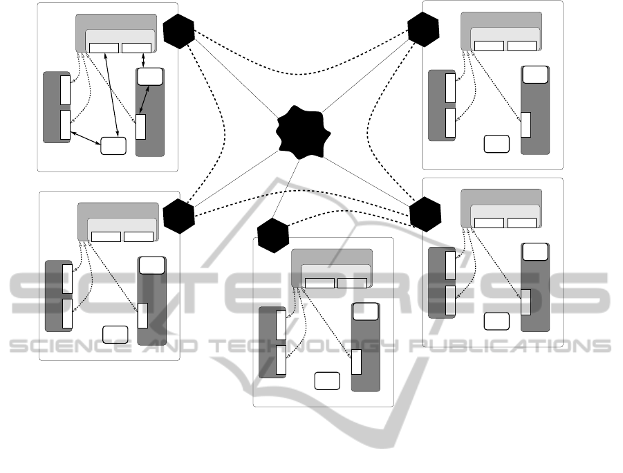
Figure 1 shows our architecture. There are 5
local networks in the figure, labelled from 1 to 5.
Each of these local networks offers local services, de-
vices, and control points. These devices, services, and
control points are connected with each other locally
through UPnP. In each local network there is one spe-
ADistributedArchitectureforRemoteServiceDiscoveryinPervasiveComputing
403
UPnP−enabled device
Control
point
Control
point 1
UPnP−enabled device 1
Service
UPnP−enabled device 2
Service 2Service 1
Service Mirror Builder
Mirrored services
Service 4 Service 3
Local network 1
Control
point
Control
point
Control
point
Control
point
Control
point
Control
point
Control
point
UPnP−enabled device
UPnP−enabled device
UPnP−enabled device
Service Mirror Builder
Mirrored services
Local network 5
Service Mirror Builder
Mirrored services
Local network 3
UPnP−enabled device
UPnP−enabled device
UPnP−enabled device
Service Mirror Builder
Mirrored services
Local network 4
UPnP−enabled device
Service Mirror Builder
Mirrored services
Local network 2
Control
point
Interconnect
client
client
Gnutella
client
client
client
Gnutella
Gnutella
Gnutella
Gnutella
Figure 1: A distributed architecture for remote service discovery (doted lines connecting local networks show the Gnutella
network overlay).
cial function (which can also be seen as a UPnP en-
abled device) called service mirror builder. This spe-
cial function will perform remote service discovery.
In addition, each local network runs a Gnutella
client software. These clients are specialized clients
that share local services to the outside world and find
services requested by their service mirror builder. The
local networks establish a Gnutella network between
them. Dotted lines connecting local networks in the
figure show the overlay of the Gnutella network.
4.1 The Local Network
A local network contains a number of (local) devices,
services, and control points. Our architecture intro-
duces a service mirror builder in every local network.
The network is an IP based network with all of these
devices connected through UPnP (the UPnP protocol
with its six steps is described in Section 2). Address-
ing is accomplished using the normal UPnP protocol.
Discovery-advertising and discovery-search are
then performed in the local network as prescribed by
the local UPnP protocol. The service mirror builder
must be aware of all the available services in the local
network, so it never ignores any multicast message. It
will also advertise its services (that are all remotely
discovered as we will see later) as they become avail-
able. During any kind of discovery-search process
(that is, whenever a control point becomes interested
in a new service) the respective control point multi-
casts a discovery message, thus searching for avail-
able services and devices in the network. All the de-
vices listen to these messages and respond whenever
any of their services match the criteria specified by
the request. Additionally, the service mirror builder
listens to these messages as well. It checks whether
the requested service is in the list of available local
services, case in which the message is ignored; other-
wise, the service mirror builder performs remote dis-
covery for that service.
Refer to Figure 1 for a closer look at one of the
local networks (namely, local network 1). This net-
work features four components: two UPnP-enabled
devices (labelled Device 1 and Device 2), one con-
trol point (Control point 1) and one service mirror
builder (SMB for short). The service mirror builder
typically resides on the smart environment gateway
(such as a connected home gateway). Suppose that
Device 1 has not introduced its service to other con-
trol points except the service mirror builder, and its
control point has discovered a mirror of a remote ser-
vice (Service 3). Device 2 is a UPnP device with 2
ICSOFT2012-7thInternationalConferenceonSoftwareParadigmTrends
404

embedded services (Service 1 and Service 2) which
are also not known to the others. Then Device 2 must
inform all the available control points in the network
about its services; it does so by multicasting a mes-
sage and thus advertising Services 1 and 2 (discovery-
advertisement). The multicast message will be re-
ceived by the service mirror builder and by Device
1. The control point of Device 1 is not interested in
(or not capable to control) either Service 1 or Service
2 and so it ignores this message. However, the service
mirror builder is aware of all the available services in
the local network, so it cannot ignore any multicast
message. The service mirror builder uses this infor-
mation for remote service discovery, which will be
discussed later. In local network 1 the service mirror
builder is interested in Service 1 and Service 2. It then
sends a message to device 1 to retrieve the description
of the two services as per the description UPnP step.
Suppose now that Device 1, Device 2, and the ser-
vice mirror builder have all discovered each other.
Control point 1 then joins the network and obtains
an IP address, but has not discovered any services to
control yet. In such a case the newly added control
point multicasts a Simple Service Discovery Protocol
(SSDP) discovery message, thus searching for avail-
able services and devices in the network (discovery-
search). The devices in the network listen to these
messages and respond whenever any of their services
match the criteria specified therein. The service mir-
ror builder listens to all these messages and proceeds
to remote discovery for the respective service when-
ever the requested service not provided locally. In
our example, Service 1 is matched with the request
of Control point 1. Therefore Device 2 unicasts a re-
sponse message to Control point 1. Now that Control
point 1 has discovered the service, it asks for a de-
scription. Once the description is received, Control
point 1 can control Service 1 in Device 2.
Consider now that Control point 1 multicasts a
discovery-search message requesting a service which
is not locally available (Service 4). The service mir-
ror builder will recognize that this service is not lo-
cally available, and so it sends a query for that service
to the local Gnutella client. The Gnutella client will
then pass that query to the Gnutella network (see Sec-
tion 4.2). Once such a service is found, a mirror of
that service is made available in the local network. In
local network 1 from Figure 1 the mirrors of the re-
mote services are shown in the service mirror builder
box (Services 3 and 4).
After the discovery step (which makes the con-
trol points aware of the available services), the con-
trol points must find out how to use these available
services (description). Advertising messages circu-
lated during discovery contain URLs from which the
control points can retrieve the description of the re-
spective devices. Once a control point has the device
or service description it can invoke actions on that ser-
vice and get result values in return. Invoking an action
in UPnP is a particular instance of Remote Procedure
Call (UPnP, 2000). The major focus of this research
contribution however is service discovery so we will
not discuss service control, eventing and presentation
any further.
4.2 Remote Service Discovery
Two major characteristics of pervasive computing are
distributedness and mobility. In such an environment
we want to connect nodes in a distributed manner and
without any dependency to a central server (such as
the presence server used in Section 3). We therefore
chose in our architecture Gnutella as the connecting
protocol, since Gnutella is a strongly decentralized
peer-to-peer system (Ilie, 2006).
Gnutella servents can share any type of resources
(Ilie, 2006). In our design they are sharing the ser-
vices available in their local networks. The overlay-
ing Gnutella network (dotted lines in Figure 1) is es-
tablished according to the protocol.
Now that both the local networks and the Gnutella
network are established, remote service discovery can
begin. Such an event happens whenever a control
point requests a service which is not locally available.
The service mirror builder then activates and tries to
remotely discover it.
Each service mirror builder has a cached descrip-
tion of all of the available local services (obtained
during the local discovery phase as explained ear-
lier). When a control point requests a service, the
service mirror builder checks in its local service di-
rectory to see if the service is already available in the
local network. If this is not the case, then the ser-
vice mirror builder proceeds to discover it remotely
by sending a request for the respective service to the
Gnutella client. The Gnutella client in turn issues a
query message asking for the requested service to the
Gnutella network according to the Gnutella protocol.
When receiving a query, a Gnutella client sends the
included service request to the local service mirror
builder, which in turn will check the availability of
the requested service in its local network. Should the
service be locally available, the service mirror builder
communicates this to the Gnutella client, which in
turn responds with a query-hit message to the origi-
nal requester. Overall, the query is answered with a
query-hit by the nodes that offer the respective ser-
vice. These nodes also send a service description and
ADistributedArchitectureforRemoteServiceDiscoveryinPervasiveComputing
405

Point 1
Control
(local)
Gnutella
(local)
SMB Gnutella
network
Gnutella
(remote)
SMB
(remote)
DeviceDevice 2
Ask description
Discovery−advertisment
Ask description Ask description Ask description
Send descriptionSend description
Send description
Send descriptionDescription
Control, etc.
N/A
Control, etc. Control, etc. Control, etc. etc.
Control,
Service 4Service 1
Discovery & ctrl of remote serv. (Serv. 4)
Serv. 1 locally OK; drop msg.
Discovery & ctrl of Serv. 1
Service 4 is locally available
Serv. 4 not available; discover and mirrorLog Serv. 1
SSDP discovery message for Service 1
Query
Service 4
Query
Service 4
Query
Service 4
Query
Service 4
Service 4 availableQuery−hit (direct path)remotely
Service 4
available
Respond to SSDP
Ask
description
Ask description
Send description
Respond to SSDP message for Service 4
SSDP discovery message for Service 4
Control, etc.
Figure 2: A sequence diagram detailing the behaviour of our distributed architecture for remote service discovery.
other information back to the node that issued the
query. This information is then be delivered to the
service mirror builder of that node, which creates a
mirror of the service in the local network. The control
points in the local network see the service just likes a
local one and can control it in the usual way.
Suppose that some control point (such as Control
point 1) requests a service which is not available in
any of the participating local networks; in such a case
the respective Gnutella client returns no hits. When-
ever the service becomes available in the local net-
work, it will be made available through discovery-
advertisement; similarly, the Gnutella client will re-
issue the corresponding query periodically until either
(a) the service becomes available in the local net-
work, (b) the service is discovered remotely, or (c)
the control point that requested the service disappears.
This mechanism extends the discovery-search mech-
anism almost transparently (but with some delay).
The functioning of the whole protocol is summa-
rized in Figure 2.
During the years many changes and refinements
have been added to Gnutella. Some refinements
and new techniques like Ultrapeers and Leaves, Dis-
tributed Hash Table, Query Routing Protocol (QRP),
and so on helped to reduce the traffic in Gnutella net-
work and have increased the efficiency of the proto-
col. These refinements can be trivially added to our
architecture.
4.3 Gnutella and UPnP Messages in the
New Architecture
We show the possibility of using the Gnutella dis-
tributed search protocol to search for services in re-
mote networks (remote services). We do this by dis-
cussing the Gnutella and UPnP message structure and
the modifications that are needed in our architecture.
In our architecture all local network components
communicate and work with each other under UPnP
protocol standards. All six steps in UPnP (addressing,
discovery, description, control, eventing and presenta-
tion) are being done as per the UPnP protocol.
As far as the remote connections are concerned,
all servents are working under the Gnutella standards
and specification. All Gnutella connect, Gnutella OK,
ping and pong messages are exactly according to the
available Gnutella protocol. The only differences
happen in the Gnutella query and Gnutella query-hit
messages (since the original messages are used for re-
questing for and responding with shared files). We
show the structure of these messages in more detail
along with recommendations for changing them to
work in the new architecture for the purpose of ser-
vice discovery instead of file sharing.
All of the Gnutella protocol messages, including
query and query-hit, include a header with the byte
structure described in Table 1 (Klingberg and Man-
fredi, 2002). The payload type indicates the type
ICSOFT2012-7thInternationalConferenceonSoftwareParadigmTrends
406

Table 1: Gnutella message header.
Bytes Description
0-15 Message ID/GUID (Globally Unique ID)
16 Payload Type
0x00 = Ping 0x01 = Pong
0x02 = Bye 0x40 = Push
0x80 = Query 0x81 = Query-Hit
17 TTL (Time To Live)
18 Hops
19-22 Payload Length
Table 2: Gnutella query message structure.
Bytes Description
0-1 Minimum speed
2 Search criteria
Rest Optional extension block
of the message. Other payload types can also be
used as long as all the participating servents support
them (Klingbergand Manfredi, 2002). Payloadlength
shows the size of the payload. The whole Gnutella
message should be no more than 4 kB in size. Im-
mediately following the message header is a payload
which can be one of the following messages: ping,
pong, query, query-hit and push (Klingberg and Man-
fredi, 2002). This message header structure will re-
main unchanged in our architecture.
The Query Message: Since queries are broadcast to
many nodes, servents normally send query messages
that are smaller than 256 bytes; however, query mes-
sages can be as large as 4 kB. A query message has
the structure shown in Table 2 (Klingberg and Man-
fredi, 2002). The rest field of a query message is used
for the original query which in our case is a query for
a remote service. The allowed extension types in the
rest field can be specified using the Gnutella Generic
Extension Protocol (GGEP), Hash/URN Gnutella Ex-
tensions (HUGE), and XML (Klingberg and Man-
fredi, 2002). The Gnutella Generic Extension Proto-
col (GGEP) allows arbitrary extensions in a Gnutella
message; a GGEP block is a framework for other ex-
tensions (Klingberg and Manfredi, 2002).
In a UPnP network service discovery is accom-
plished using Simple Service Discovery Protocol
(SSDP). All SSDP messages are sent using the HTTP
protocol. The HTTP and Gnutella protocols are both
application layer protocols. The fundamental data in
a SSDP discovery search or discovery-advertisement
message (in a UPnP network) contains a few essen-
tial specifics about the device or one of its services
(its type, universally unique identifier, etc.) (UPnP
Forum, 2008). All this information can be readily
Table 3: Gnutella query-hit message structure.
Bytes Description
0 Number of Hits
1-2 Port
3-6 IP Address
7-10 Speed
11- Result Set
Result set structure:
Bytes Description:
0-3 File Index
4-7 File Size
8- File Name (null-terminated)
x Extensions Block (null-terminated)
encoded in a GGEP extension by the service mirror
builders and then sent to the Gnutella network agent.
Then the Gnutella network agent can put this GGEP-
formatted information in the Rest part of a Gnutella
query message and send it to the Gnutella network.
The Query-hit Message: The structure of a query-hit
message is shown in Table 3 (Klingberg and Man-
fredi, 2002). The result set is used for the response
to the query; its structure is also shown in the table.
The first three fields of the result set are defined
specifically to hold information about a requested file
or file portion, as Gnutella is mainly used for file shar-
ing. In our case it is possible to redefine these fields;
to prevent increased complexity and extra work to de-
fine a new specification, we recommend that these
fields be filled with some default labels. In other
words these fields of the result set are simply ignored.
GGEP, HUGE, and plain text metadata are all al-
lowed in the extension block. We recommend that
the response messages from service mirror builders
be formatted in a GGEP extension and sent back to
the network in the extensions field of the query-hit
message.
5 CONCLUSIONS
Service discovery plays an important role in pervasive
computing. At the same time pervasive computing
creates many challenges for service discovery proto-
cols, one of them being remote service discovery.
We described in Section 3 three architectures that
enable the service discovery protocols and in particu-
lar UPnP to discover remote services. Similar to their
attempts, we introduced a new approach that is de-
centralized and fully distributed. We therefore believe
that our approach offers better compatibility with per-
vasive computing.
ADistributedArchitectureforRemoteServiceDiscoveryinPervasiveComputing
407

The core part of the new architecture is the new
function in a UPnP network called service mir-
ror builder and its cooperation with a specialized
Gnutella client software to discover remote services
and then present these remote services as local ones.
Conversely, a service mirror builder can also control
local services to serve them as remote services for
other, remote service mirror builders. The service
mirror builder communicates with the specialized
Gnutella client software (from the point of view of
the local network however the service mirror builder
is just a UPnP-enabled device). We used UPnP for il-
lustration purposes, but the service mirror builder can
be defined based on any service discovery protocol
(Bluetooth, Apple Bonjour, etc.). Our solution is in
fact general and not dependent on any particular ser-
vice discovery protocol.
We propose Gnutella as a distributed search pro-
tocol for discovering remote services. The very de-
sign of a Gnutella network as a decentralized and dis-
tributed protocol moves this remote service discovery
architecture one step ahead toward truly distributed
computing. Overall our architecture is more compat-
ible and better adapted to pervasive computing that
both the Atom base and Presence service solutions.
REFERENCES
Belimpasakis, P. and Stirbu, V. (2007). Remote access
to universal plug and play (UPnP) devices utilizing
the Atom publishing protocol. In International Con-
ference on Networking and Services, page 59. IEEE
Computer Society.
Bluetooth (2001). Specification of the Bluetooth System
Version 1.1. Bluetooth Special Interest Group (SIG).
www.tscm.com/BluetoothSpec.pdf.
Buyukkaya, E., Abdallah, M., and Cavagna, R. (2009).
VoroGame: A hybrid P2P architecture for massively
multiplayer games. In 6th IEEE Consumer Commu-
nications and Networking Conference (CCNC), pages
1–5. IEEE.
Cheshire, S., Aboba, B., and Guttman, E. (2005). Dynamic
Configuration of IPv4 Link-Local Addresses. Internet
Engineering Task Force. RFC 3927.
Clip2 (2003). The Gnutella Protocol Specification
Version 0.4. Clip2 Distributed Search Services.
www.stanford.edu/class/cs244b/gnutella
protocol 0.4.
pdf.
Cohen, B. (2008). The BitTorrent Protocol Specification.
www.bittorrent.org/beps/bep
0003. html.
Engelstad, P., Zheng, Y., and Tore, J. (2003). Service
discovery and name resolution architectures for on-
demand MANETs. In 23rd International Conference
on Distributed Computing Systems, pages 736–742.
IEEE Computer Society.
Feng, W. (2010). Remote service provision for connected
homes. PhD thesis, De Montfort University.
Gtk-Gnutella (2011). Gnutella Bootstrapping. gtk-gnutella.
sourceforge.net/en/?page=bootstrap.
H¨aber, A. (2010). Remote Service Discovery and Con-
trol for Ubiquitous Service Environments in Next-
Generation Networks. PhD thesis, University of
Agder.
Ilie, D. (2006). Gnutella Network Traffic-Measurements
and Characteristics. Master’s thesis, Blekinge
Tekniska H¨ogskola.
Kawamoto, E., Kadowaki, K., Koita, T., and Sato, K.
(2009). Content sharing among UPnP gateways on un-
structured P2P network using dynamic overlay topol-
ogy optimization. In 6th IEEE Consumer Communi-
cations and Networking Conference (CCNC), pages
1–5. IEEE.
Klingberg, T. and Manfredi, R. (2002). Gnutella 0.6. Net-
work Working Group.
Ogawa, M., Hayakawa, H., Koita, T., and Sato, K. (2007).
Transparent UPnP interactions over global network.
In Proceedings of SPIE, volume 6794, page 67944P.
Oram, A. (2001). Peer-to-Peer: Harnessing the Benefits of
a Disruptive Technology. O’Reilly Media.
Schollmeier, R. (2001). A definition of peer-to-peer net-
working for the classification of peer-to-peer architec-
tures and applications. In 1st International Confer-
ence on Peer-to-Peer Computing, pages 101 –102.
Sun Microsystems (2001). Jini Technology Core Platform
Specification Version 1.2. www-csag.ucsd.edu/ teach-
ing/cse291s03/Readings/core1
2.pdf.
UPnP (2000). Understanding Universal Plug and
Play. White paper: www.upnp.org/download/
UPNP
understandingUPNP.doc.
UPnP Forum (2008). UPnP Device Architecture 1.1.
UPnP forum. www. upnp.org/specs/arch/UPnP-arch-
DeviceArchitecture-v1.1.pdf.
Weiser, M. (1993). Some computer science issues in
ubiquitous computing. Communications of the ACM,
36(7):75–84.
Zhu, F., Mutka, M., and Ni, L. (2005). Service discovery in
pervasive computing environments. Pervasive Com-
puting, 4(4):81–90.
ICSOFT2012-7thInternationalConferenceonSoftwareParadigmTrends
408
