
Budget Extension Schemes for Nx10 Gbit/s DPSK-based
TDM/WDM PON
A. Emsia, Q. T. Le, T. von Lerber, D. Briggmann and F. Kueppers
Institute of Microwave Engineering and Photonics, TU Darmstadt, Merckstr. 25, Darmstadt, Germany
Keywords:
Wavelength-Division-Multiplexed Passive Optical Network (WDM PON), Differential-Phase-Shift-Keying
(DPSK), Semiconductor Optical Amplifier (SOA), Delay Line Interferometer (DLI), Saturated Collision
Amplifier (SCA).
Abstract:
We present a new TDM/WDM PON scheme utilizing PSK (phase shift-keying) at 10 Gbit/s per λ-channel as
the modulation format along the feeder line and an SOA (semiconductor optical amplifier) as the amplifying
component at the remote node. One single DLI (Delay Line Interferometer) converts all λ-channels from PSK
to OOK (on-off keying), the modulation format which is used along the access line and one single SOA are
experimentally demonstrated to be sufficient providing a power budget increase of up to 46.8 dB.
1 INTRODUCTION
Fibre-to-the-Home (FTTH) or Building (FTTB) is an
access network technology that delivers the highest
possible speed of Internet connection by using op-
tical fibre that runs directly to the home, building
or office. Gigabit-capable Passive Optical Network
(PON) systems, such as GPON standardized by ITU-
T G.984 and G-EPON standardized by IEEE 802.3ah,
are now being mass-deployed in various FTTH/B
markets around the world. These systems use Time-
division multiplexing (TDM) / Time-division Multi-
ple Access (TDMA) to manage the connection of N
users (up to 128) to one optical port, the connection
between end users and Optical Line Terminal(OLT)
(Willner et al., 2009) (Jia et al., 2010) (Davey et al.,
2006). The follow-up PON solutions use 10 Gbit/s for
downstream transmission known as XGPON (ITU-
T G.987) and 10GE-PON (IEEE p802.3) based on
the same TDM technology. With the continuous in-
crease in bandwidth demand generated by consumer
and business applications (HD TV, cloud computing,
online gaming, video-conferencing, etc.), and with
the requirements of high-speed mobile backhaul for
Long Term Evolution (LTE) networks, the need for
a new, higher capacity access architecture becomes
clear. Wavelength-division-multiplexed passive opti-
cal network (WDM-PON), whose simple topology is
shown in Figure 1, is an efficient choice for future
fibre access networks, and one of the most likely to
solve the challenges of next generation access net-
Figure 1: Wavelength-division-multiplexed passive optical
network.
work (NGAN) as it can provide a point-to-point con-
nectivity to multiple remote locations sharing the ma-
jor part of the fibre plan. This WDM-PON architec-
ture provides the most scalable, cost effective, and
future proof solution available to address the capac-
ity, security, and distance capabilities that network
operators require while leveraging the benefits of a
passive infrastructure. All these factors combine to
make WDM-PON poised to become the disruptive
next-generation access solution. It will enable high
speed access for business, mobile backhaul, and even-
tually FTTH, while also enabling operators to build
converged networks and consolidate the access net-
work.
In this paper, we present a new TDM/WDM PON
configuration based on Return to Zero(RZ) phase
shift-keying signal (PSK) at 10 Gbit/s. The network
extension by the use of a single semiconductor optical
amplifier (SOA) for all channels is demonstrated.
373
Emsia A., T. Le Q., von Lerber T., Briggmann D. and Kueppers F..
Budget Extension Schemes for Nx10 Gbit/s DPSK-based TDM/WDM PON.
DOI: 10.5220/0004057603730377
In Proceedings of the International Conference on Data Communication Networking, e-Business and Optical Communication Systems (OPTICS-2012),
pages 373-377
ISBN: 978-989-8565-23-5
Copyright
c
2012 SCITEPRESS (Science and Technology Publications, Lda.)

Tx
1
Tx
6
DLI
Feeder
Access
OLT
Remote node
1:M splitter
ONU
SOA
Figure 2: Downstream WDM PON architecture.
2 WDM PON ARCHITECTURE
The proposed architecture is shown in Figure 2. It is
comprised of 5 elements: 1) Optical Line Terminal
(OLT), 2) the feeder line, 3) the remote node, 4) split-
ters and the access line, and 5) Optical Network Unit
(ONU). In this architecture, the PSK signal is consid-
ered for downstream transmission as it has many ad-
vantages compared to conventional OOK modulation
format (for instance, better tolerance to fibre disper-
sion and non-linearities). The OLT consists of DPSK
transmitters which offer the wavelengths from 1 to
N for downstream each to its own TDM PON tree
(splitters in the Figure 2 represent the PON trees). In
upstream scenario, TDM technology used to transmit
signals up to OLT. Each user has a dedicated time slot.
At the remote node, only one DLI is used re-
gardless of number of channels.Namely, all six wave-
lengths are converted from DPSK to OOK at the same
time, no need to demodulate the channels separately.
The DWDM signals are then demultiplexed by an
AWG demux and the wavelengths are sent to respec-
tive individual TDM PON trees. At the ONU, the
receivers need no individual demodulators, because
the modulation format transformation from the DPSK
to OOK is performed simultaneously for all ONUs at
the remote node. The proposed downstream PON is
therefore compatible with commercial XGPON1 net-
work terminals. Only DPSK downstream transmis-
sion at the OLT is needed, which could be performed
by cost-efficient direct phase, or frequency modulated
lasers (Vodhanel et al., 1990) (Maher et al., 2010).
The budget extension by the use of a single SOA at
the remote node is experimentally demonstrated and
the possibility to use a saturated collision amplifier
(SCA) (Tervonen et al., 2010) is discussed in the next
sections.
Access
F
eeder
Remote node
Access budget
10 Gb/s RZ DPSK
Feeder budget
Figure 3: Measurement setup.
3 MEASUREMENTS
3.1 Experimental Setup
The measurement setup is shown in Figure 3 where
six downstream channels of 10 Gbit/s PON are at
1537.388 nm,1542.93 nm ,1543.64 nm,1553.329 nm
,1554,101 nm ,and 1556.55 nm generated by DFB
laser diodes. The channels are combined through
AWG and modulated by Mach Zehnder Modula-
tor. The modulator operates in push-pull mode and
generates RZ-DPSK signals at 10 Gbit/s (PRBS of
2
31
-1). In order to have uncorrelated data on each
wavelength, the channels are separated, transmitted
through different fibre lengths and again combined
by a multiplexer. The AWGs have 100 GHz chan-
nel spacing and 50 GHz 3-dB bandwidth. The EDFA
is used to compensate the loss of the multiplexers and
the demultiplexer, each channel has 8 dBm power at
the input of feeder variable optical attenuator. The
line between OLT and the remote node is termed as
feeder line and the one between remote node and
ONU is the access line.
A DLI is employed to convert DPSK into OOK
signal. The receiver is a p-i-n photodiode with sensi-
tivity of -17 dBm at BER 10
−9
and -22 dBm 10
−3
.
OPTICS2012-InternationalConferenceonOpticalCommunicationSystems
374
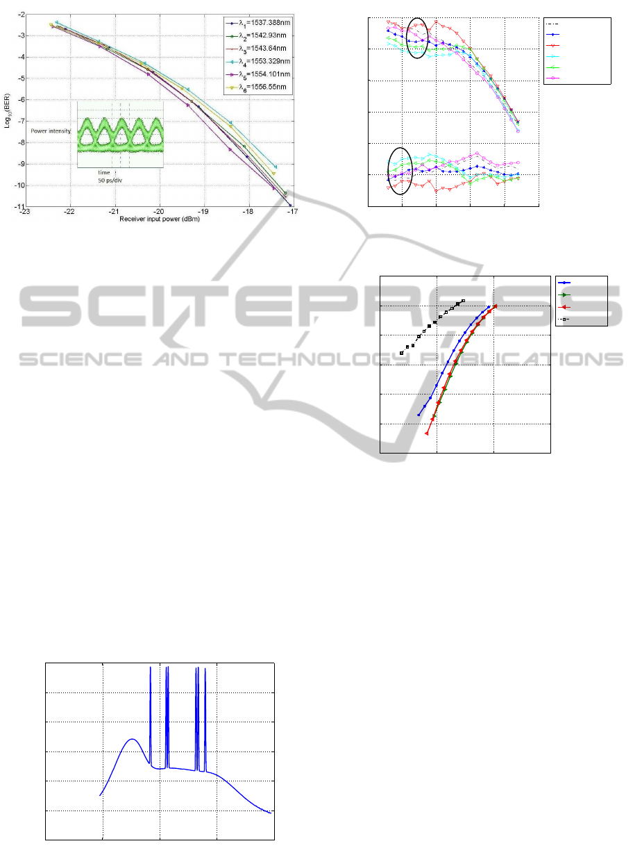
Figure 4: BER versus received power for the case without
SOA.
3.2 Experimental Results
The Figure 4 depicts the bit error ratio versus receiver
input power for all six channels for the constructive
output of the DLI as well as corresponding eye dia-
gram of a channel. As mentioned above the sensitiv-
ity range of our receiver at the time of measurements
was from -17 dBm to approximately -22 dBm. The
measurements are done for back-to-back case in the
absence of the SOA.
The Figure 5 demonstrates the spectrum of six
channels with nearly the same power (the spectrum
is acquired after DLI, refer to Figure 2). All six chan-
nels show almost the same performance.
The SOA is now considered in the setup as de-
picted in the Figure 3 to see how it will improve the
power budget of the link. The bias current of SOA is
set to 300 mA at the temperature of 17.2
o
C. The Fig-
ure 6 displays the gain and noise figure of the SOA
used in the experiment for vairous channels. The
highest gain of 34.8 dB is achieved at 1554.10 nm
with NF of 8.5 dB.
1500 1520 1540 1560 1580
−70
−60
−50
−40
−30
−20
−10
Wavelength[nm]
P[dBm]
Figure 5: The spectrum of all channels, BWR 0.1nm.
−50 −40 −30 −20 −10 0
5
10
15
20
25
30
35
Pin[dBm]
NF and Gain[dB]
1542.93nm
1537.388nm
1554.10nm
1553.27nm
1556.56nm
1543.94nm
Noise figure
Gain
Figure 6: The noise figure and gain of SOA.
10 15 20 25
−12
−10
−8
−6
−4
−2
0
Access budget(dB)
logBER
5.6 dB
15.6 dB
25.6 dB
35.6 dB
Figure 7: BER versus access budget for varying feeder bud-
gets.
The Figure 7 displays the bit error ratio curves over
access budget for different values of optical feeder
budget considering one channel (1543.64nm).As
seen, for larger values of feeder budget, the bit er-
ror ratio decreases. This is due to domination of ASE
noise produced by the SOA. On the other hand lower
values of feeder budget show weaker performance,
this may be a result of non-linearities caused by the
SOA.
The Figure 8 illustrates BER map for 1543.64
nm.Considering use of forward Error Correc-
tion(FEC),the BER of 10
−3
can be selected. In this
case, at the feeder budget of 17.5 dB the access bud-
get is 18.5 dB. Therefore, the total optical budget is
36 dB. An avalanche photodiode (APD) can be used
to further increase the access budget of the system. In
the absence of SOA, the maximum feeder budget can
be 21 dB, however, SOA can result in higher feeder
budget. In other words, the input signal to the feeder
can be attenuated more than without SOA. For in-
stance, in the Figure 8 at feeder budget of 30 dB we
have access budget of 16.8 dB, this gives total optical
BudgetExtensionSchemesforNx10Gbit/sDPSK-basedTDM/WDMPON
375

10 12 14 16 18 20
5
10
15
20
25
30
35
40
45
−3
−3
−3
Access budget(dB)
Feeder
budget(dB)
Figure 8: BER map of 6-wavelength setup.
budget of 46.8 dB.
4 SATURATED COLLISION
AMPLIFIER
The SCA arrangement consists of a delay interferom-
eter, a pair of circulators, and an SOA (see Figure
9). The delay interferometer demodulates the input
DPSK signal into a pair of complementary OOK sig-
nals that are coupled into the circulators, which direct
the opposite polarity signals through the SOA (Ter-
vonen et al., 2010). The signals are amplified while
they simultaneously traverse the SOA gain medium
from the opposite directions, and finally the signals
are coupled out via the circulators.
As discussed in (Tervonen et al., 2010), this arrange-
ment permits saturated SOA operation, which results
in the maximized output power, low ASE noise, and
virtual absence of pattern effects. In other words, the
common negatives of an SOA are effectively miti-
gated. We compared the performance when the SOA
was used in the conventional linear regime with the
SCA arrangement and found up to 10-dB power bud-
get improvement from a single output arm. When the
output doubling is taken in account, the power budget
improvement over the linear operation SOA rises up
Tx
1
Tx
6
DLI
Feeder
OLT
Remote node
Access
1:M splitter
ONU
SOA
Figure 9: TDM/WDM using SCA.
to 13 dB. In collaboration with Orange-France Tele-
com Labs we show in (Le et al., 2011) that the SCA
arrangement can even be used for amplification of
multiple simultaneous wavelengths without a notice-
able penalty. And the compatibility of the SCA for
reach extension of a commercial single-wavelength
XGPON1 system was experimentally demonstrated
(Saliou et al., 2011).
5 CONCLUSIONS
In this paper, a power budget extension scheme has
been shown. We demonstrated our scheme using
a SOA and one DLI. Optical budget extension of
46.8 dB with in a 10 Gbit/s TDM/WDM PON was
achieved. We showed that there is trade-off between
higher and lower values of the feeder budget. The ex-
periment performed for six-channel case, i.e., for total
transmission of 60 Gbit/s.
6 FUTURE WORKS
The SCA power extension method has been explained
in section 4. The SCA has not been investigated for 60
Gbit/s WDM/PON system. One of the future works
will be to investigate the difference between the sin-
gle SOA and the SCA setup. Additionally, the bit
rate will be increased to see the performance of the
proposed model. Furthermore, power equalization in
burst mode transmission in upstream case is under in-
vestigation in the laboratory.
REFERENCES
Davey, R., Kani, J., Bourgart, F., and McCammon, K.
(2006). Options for future optical access networks. In
ECOC, Geneva, Switzerland. IEEE Communications
Magazine.
Jia, W., Xu, J., Liu, Z., Tse, K., and Chan, C. (2010). Gener-
ation and transmission of 10-gb/s rz-dpsk signals us-
ing a directly modulated chirp managed laser. In OFC.
IEEE.
Le, Q. T., Saliou, F., Xia, R., Chanclou, P., von Lerber, T.,
Tervonen, A., Mattila, M., Weiershausen, W., Honka-
nen, S., and Kueppers, F. (2011). Tdm/dwdm pon
extender for 10 gbit/s downstream transmission. In
ECOC, Geneva, Switzerland. OSA.
Maher, R., Barry, L. P., and Anandarajah, P. M. (2010). Cost
efficient directly modulated dpsk downstream trans-
mitter and colourless upstream remodulation for full-
duplex wdm-pons. In OFC, San Diego, CA, USA.
OSA.
OPTICS2012-InternationalConferenceonOpticalCommunicationSystems
376

Saliou, F., Xia, R., Le, Q. T., Chanclou, P., Tervonen, A.,
Mattila, M., von Lerber, T., Weiershausen, W., Honka-
nen, S., and Kueppers, F. (2011). Reach extenders
based on optical amplification for xgpon1 optical ac-
cess networks. In ECOC, Geneva, Switzerland. OSA.
Tervonen, A., Mattila, M., Weiershausen, W., von Ler-
ber, T., Parson, E., Chaouch, H., Marculescu, A.,
Leuthold, J., and Kueppers, F. (2010). Dual output soa
based amplifier for pon extenders. In ECOC, Torino,
Italy. IEEE.
Vodhanel, R. S., Elrefaie, A. F., Iqbal, M. Z., Wagner, R. E.,
Gimllet, J. L., and Tsuji, S. (1990). Performance of
directly modulated dfb lasers in 10-gb/s ask, fsk, and
dpsk lightwave systems. In J. Lightw. Technol., vol. 8,
no. 9,pp. 1379-1386. IEEE.
Willner, A. E., Yu, C., and Xie, Y. (2009). Handbook
of Optics,WDM fiber optic communication networks.
McGraw-Hill, Inc., New York, 3rd edition.
BudgetExtensionSchemesforNx10Gbit/sDPSK-basedTDM/WDMPON
377
