
The Modular Behavioral Environment for Humanoids and other Robots
(MoBeE)
Mikhail Frank, J
¨
urgen Leitner, Marijn Stollenga, Gregor Kaufmann, Simon Harding,
Alexander F
¨
orster and J
¨
urgen Schmidhuber
Dalle Molle Institute for Artificial Intelligence (IDSIA), CH-6928 Manno-Lugano, Switzerland
Facolt
`
a di Scienze Informatiche, Universit
`
a della Svizzera Italiana, CH-6904 Lugano, Switzerland
Dipartimento Tecnologie Innovative, Scuola Universitaria Professionale della Svizzera Italiana,
CH-6928 Manno-Lugano, Switzerland
Keywords:
Robotics, Modelling, Simulation, Architecture, Framework, Humanoid, Adaptive Roadmap Planning,
Machine Learning, Cooperative Robots, Shared Workspace, Autonomous Adaptive Behavior, Unstructured
Environment.
Abstract:
To produce even the simplest human-like behaviors, a humanoid robot must be able to see, act, and react,
within a tightly integrated behavioral control system. Although there exists a rich body of literature in Com-
puter Vision, Path Planning, and Feedback Control, wherein many critical subproblems are addressed individ-
ually, most demonstrable behaviors for humanoid robots do not effectively integrate elements from all three
disciplines. Consequently, tasks that seem trivial to us humans, such as pick-and-place in an unstructured envi-
ronment, remain far beyond the state-of-the-art in experimental robotics. We view this primarily as a software
engineering problem, and have therefore developed MoBeE, a novel behavioral framework for humanoids and
other complex robots, which integrates elements from vision, planning, and control, facilitating the synthesis
of autonomous, adaptive behaviors. We communicate the efficacy of MoBeE through several demonstrative
experiments. We first develop Adaptive Roadmap Planning by integrating a reactive feedback controller into
a roadmap planner. Then, an industrial manipulator teaches a humanoid to localize objects as the two robots
operate autonomously in a shared workspace. Finally, an integrated vision, planning, control system is applied
to a real-world reaching task using the humanoid robot.
1 INTRODUCTION
To produce even the simplest autonomous, adap-
tive, human-like behaviors in an unstructured envi-
ronment, a humanoid robot must be able to:
1. Identify and localize salient environmental fea-
tures, such as people and objects.
2. Execute purposeful motions to either interact with
the environment or avoid doing so.
These motivate at least three distinct fields of re-
search, namely: Computer Vision, Motion Planning,
and Feedback Control. Each of these topics is well
represented in the robotics literature, however the so-
lutions they propose are often isolated from one an-
other by different sets of simplifying assumptions. To
enable a robot to autonomously interact with a real
world, unstructured environment, even in a simple
way, an integrated system of solutions to key vision,
planning, and control problems is required.
The interrelatedness of Computer Vision, Motion
Planning, and Feedback Control is problematic for
experimental roboticists. Most of the research in these
fields focuses on well posed problems that belong
to one of the three topics above. However to test,
validate and demonstrate proposed solutions on real
hardware usually requires that other reliable solutions
are also available. Current research must always be
integrated with peripheral components related to the
“other things” one must do to interact with a robot
and test a behavior. The development overhead is
significant, and the state of the art in prototyping au-
tonomous, adaptive behavior on real physical robots
stands to benefit greatly from improved software en-
gineering practices.
Historically, roboticists have often been com-
pelled to “reinvent the wheel”, continually re-
implementing necessary software components as new
hardware becomes available or other software com-
ponents change. In recent years, the topic of soft-
ware engineering has received increased attention
from the robotics community, and “robotics plat-
304
Frank M., Leitner J., Stollenga M., Harding S., Förster A. and Schmidhuber J..
The Modular Behavioral Environment for Humanoids and other Robots (MoBeE).
DOI: 10.5220/0004041703040313
In Proceedings of the 9th International Conference on Informatics in Control, Automation and Robotics (ICINCO-2012), pages 304-313
ISBN: 978-989-8565-22-8
Copyright
c
2012 SCITEPRESS (Science and Technology Publications, Lda.)

forms”, such as Yet Another Robot Platform (YARP)
(Metta et al., 2006; Fitzpatrick et al., 2008), Robot
Operating System (ROS) (Quigley et al., 2009), and
Microsoft Robotics Studio (MSRS) (Jackson, 2007),
have gained widespread popularity. Not only do these
middleware solutions abstract away the details of sen-
sors and actuators, they offer simple network commu-
nication from virtually any language on Mac, Win-
dows or Linux. Robots can be controlled with rela-
tive ease by one or more distributed applications run-
ning on a cluster. By providing hardware abstraction,
YARP, ROS, and MSRS have drastically improved
the efficiency with which experimental robots can be
programmed. In the process of developing behaviors,
we would do well to follow the example set by these
projects, and develop modular, reusable behavioral
components around abstract interfaces.
Rodney Brooks was successful in building au-
tonomous behaviors incrementally, from modu-
lar components with his Subsumption Architecture
(Brooks, 1991). His embodied “Critters” were pre-
dominantly simple mobile robots and they operated
with considerable autonomy in real-world settings. In
this paper we introduce a modular behavioral frame-
work for humanoids and other complex robots, which
is in many ways similar to the Subsumption Architec-
ture.
The Subsumption Architecture is based on asyn-
chronous networks of Finite State Machines (FSM)
and one of its defining characteristics is that the it
does not maintain a world model. Instead, sensors are
connected directly to actuators via the FSM network.
Brooks argues that the world is its own best model,
and the claim is well demonstrated in the domain of
mobile robots. However, we are interested in devel-
oping manipulation behaviors for humanoids, and this
poses a different set of problems than does the control
of a mobile robot.
Consider for a moment the relationship between
the sensory and action spaces of mobile robots and
humanoids respectively. Mobile robots have a few
controllable degrees of freedom (DOF), and are con-
fined to move on a planar surface. They typically
carry a number of cameras or range finding sensors,
arranged radially about the robot and facing outward.
Such a sensor array gives a natural representation of
obstacles and free space around the robot, and be-
havioral primitives can therefore be designed conve-
niently in that same planar space.
A humanoid, on the other hand, has a very large
number of controllable DOF, and operates in 3D
space where an object has 6DOF. Still, it has a similar
sensory system to the mobile robot, an array of cam-
eras or range finders, which capture 2 and 3D projec-
tions of the state of the high dimensional humanoid-
world system. When compared to a mobile robot, the
humanoid is quite information poor with respect to
the size of its action space.
It is for this reason that in contrast to the Sub-
sumption Architecture, we have built MoBeE around
a parsimonious, egocentric, kinematic model of the
robot/world system. The model provides a Cartesian
operational space, in which we can define task rel-
evant states, state changes, cost/objective functions,
rewards, and the like. By computing forward kine-
matics, and maintaining a geometric representation of
the 3D robot/world system, we can define a useful
and general state machine, that does not arise natu-
rally from the “raw” sensory data.
In addition to providing a task space for behav-
iors, the kinematic model is the center of our hub-
and-spokes behavioral architecture (figure 1). We de-
compose behavior into three abstract tasks that corre-
spond to key objectives in Computer Vision, Motion
Planning, and Feedback Control. The Sensor pro-
cesses sensory data (visual data in the experiments
presented here) and reports the world state, the Agent
plans actions that are temporally extended and may
or may not be feasible, and the Controller reacts to
particular world states or state changes, suppressing
commands from the Agent, and issuing its own com-
mands to avoid danger for example. Our implementa-
tion is similar to the subsumption architecture in that
MoBeE tightly integrates planning and control, which
drastically facilitates the development of autonomous,
adaptive behaviors.
In contrast to the Subsumption Architecture how-
ever, the hub-and-spokes model of MoBeE allows us
to easily combine, compare, and contrast different
behavioral modules, even running them on different
hardware, all within the same software framework.
In the following two sections we describe our behav-
ioral decomposition in some detail, according to the
requirements listed at the beginning of this section.
To paraphrase these, the robot must be able to “see”
and “act”.
1.1 To See
When humans “see” an object on the table, it’s not
really the same behavior as when we see a face or a
painting or a page of text. Seeing to facilitate reaches
and grasps implies that we can recognize objects of
interest in images and that we can use the visual in-
formation to build representations of our surround-
ings, which facilitate motion planning. For the pur-
poses of the work presented here, “seeing” will be
considered in terms of two tasks, identifying objects
TheModularBehavioralEnvironmentforHumanoidsandotherRobots(MoBeE)
305
FILTERED YARP
Control Board Interface
Encoder
Positions
Control
Commands
Port Filter
Robot Model
-Fwd Kinematics
-Collision Detection
MoBeE
World Model Interface
(YARP)
States of
Known Objects
Control
Commands
Sensory
Data
Agent
Sensor
Detector
Locator
icVision
Sensory Loop
Abstract Reactive
Controller
Model State
Images
Controller
Inherits
Model
State
YARP
Control
Board
Interface
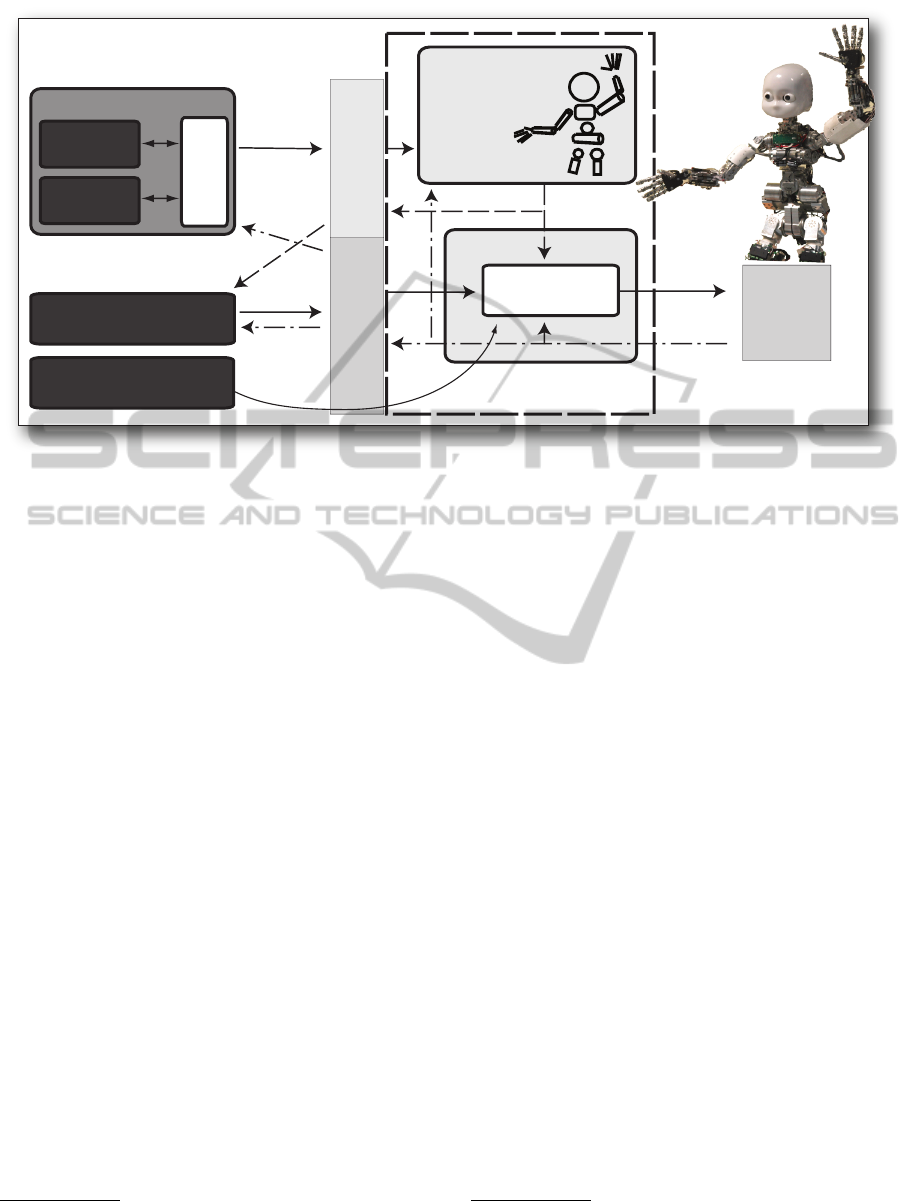
Figure 1: Simplified architecture of the MoBeE system - The Sensor, the Agent and the Controller (left), interact with the
iCub humanoid robot through MoBeE. The iCub’s behavior is decomposed and represented in terms of three weakly coupled
behavioral modules, the Sensor, (composed of the Detector, the Locator) the Agent, and the Controller.
of interest, and mapping locations from visual space
to operational space. We therefore define the Sen-
sor in terms of the following two components, which
map nicely onto the image segmentation (Forsyth and
Ponce, 2002) and stereo-vision (Hartley and Zisser-
man, 2000) literature, respectively:
1. Detector: Segment salient regions of Pixel Space
2. Locator: Map pixel pairs to 3-Space
It should be noted that we currently avoid the issue
of modeling new objects automatically by handcraft-
ing a geometric model of each discoverable object.
1.2 To Act
The question of how “action” should be represented is
particularly challenging from a technical standpoint
because the Motion Planning and Feedback Control
communities have somewhat different approaches to
controlling a robot. The Motion Planning approach is
formulated around sampling the configuration space
and constructing feasible trajectories
1
. By sampling,
Motion Planning algorithms can explore. The feasi-
bility of each trajectory is verified preemptively by
collision detection computations, and an “action” is
the execution of a whole trajectory that interpolates
two configurations, which are not necessarily nearby
one another.
1
For more information on Motion Planning, we refer
the interested reader to the recent textbook by Steven M.
LaValle (LaValle, 2006).
The Feedback Control approach on the other hand
generates control commands continuously, according
to locally available information from a model
2
. The
next control command is computed deterministically,
based on the current error signal, and “action” is
taken at a very high frequency (compared to the Mo-
tion Planning paradigm) to transition from the current
state to some new state, which is necessarily in the
neighborhood of the current state. Feedback Control
does not explore. Instead, it reacts in an attempt to
keep the state of the robot near some reference trajec-
tory.
We propose that integrating these two modes of
control, which is a challenging software engineering
problem, can drastically facilitate the synthesis of au-
tonomous behaviors. To our behavioral abstraction
we add:
1. Agent: Explore the configuration space, and plan
temporally extended actions.
2. Controller: React to the robot states or state
changes in realtime.
We now address integrating the Agent, the Con-
troller, and the Sensor (comprised of the Detector and
the Locator) into a unified, yet modular behavioral
framework.
2
For more information on Feedback Control, please
see the textbook by Franklin, Powell, and Emami-Naeini
(Franklin et al., 1994)
ICINCO2012-9thInternationalConferenceonInformaticsinControl,AutomationandRobotics
306
2 MoBeE IMPLEMENTATION
Although we are primarily interested in humanoids,
we have gone to some lengths to keep the infrastruc-
ture presented here as general and flexible as possi-
ble. Robot models are loaded from XML
3
at run-time,
and in principal the framework is compatible with any
YARP device. We also supports multiple robots, op-
erating in a shared workspace.
At the core of MoBeE is a parsimonious, egocen-
tric, kinematic model (figure 2), which does collision
detection
4
while driven by the state of the actual hard-
ware. Coupled to the kinematic model is a port fil-
ter (figure 3) that proxies YARP’s ControlBoardInter-
face.
MoBeE aggregates contributions from the Sen-
sor, Agent, and Controller, which run asynchronously
on different computers, and it periodically communi-
cates the next control command to the robot. This
architecture allows the Controller to play man-in-the-
middle between the Agent and the iCub, supressing
the Agent’s commands when necessary. The Con-
troller can:
1. Directly control the iCub.
2. Respond to state changes in the kinematic robot
model.
3. Supress input from the Agent.
4. Process the stream of commands from the Agent
in realtime.
Because the Sensor, the Agent and the Controller
are decoupled, communicating passively by influenc-
ing the state of the robot/world system, we are able
to experiment with almost arbitrary combinations of
behavioral components.
2.1 Adaptive Roadmap Planning with
Agent/Controller Architecture
In this section we develoop an Agent/Controller pair
and exploit MoBeE to implement Roadmap Planning
in an adaptive way. With respect to the overall sta-
bility and robustness of the integrated control system,
a critical issue is that the Agent and Controller must
behave synchronously. Inspired by fault-intolerant
3
Our XML files express robots’ kinematics using “Zero
Reference Position” notation (Gupta, 1986; Kazerounian
et al., 2005b; Kazerounian et al., 2005a), which is far sim-
pler and more intuitive than the popular Denavit-Hartenberg
convention (Denavit and Hartenberg, 1955).
4
Collision detection in MoBeE is handled by the
open source Software Library for Interference Detection
(FreeSOLID) (van den Bergen, 2004).
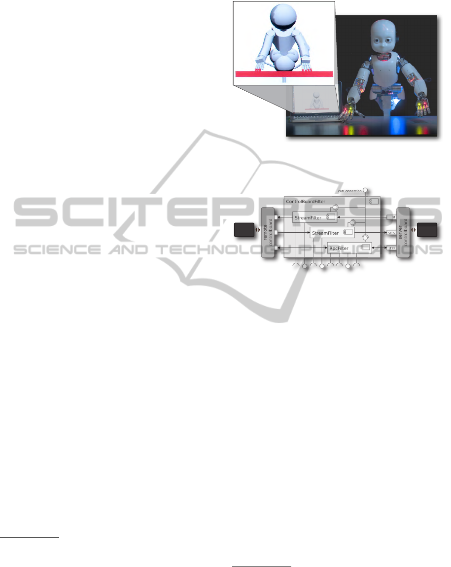
Figure 2: The kinematic model within MoBeE detects im-
pending collision between the iCub’s fingers and the table.
Colliding geometries are rendered in red.
Agent
Robot
Figure 3: The port filter within MoBeE proxies YARP’s
ControlBoardInterface (Kaufmann, 2010).
applications such as enterprise databases, we adopt
a transactional communication model. Borrowing
some terminology from the database community, the
Agent will try to “commit” its plans by sending them
to the hardware to be executed. In the event that a
plan turns out to be infeasible, the state of the hard-
ware will be “rolled back” by the Controller, before
the Agent is allowed to do anything else. Importantly,
we implement this transactional communication pro-
tocol without introducing any dependancy between
the Agent and the Controller. The Controller can see
the commands that are issued by the Agent, and it can
disable the filteredControlBoardInterface to which the
Agent is connected, however there is no symmetric
communication between the two modules.
Consider the following Agent module, which is
built around a roadmap graph G(V, E)
5
. The graph
is constructed incrementally by connecting new sam-
ples q
new
to their k nearest neighbors
6
via algorithm
1, CONNECT (q
new
, k). Motions are planned by al-
gorithm 2, GOT O(q
desired
), which in our implemen-
tation relies on Dijkstra’s shortest path. Algorithm 3,
5
Our graph implementation relies on Boost (The Boost
Graph Library, 2012)
6
Efficient nearest neighbor searching is provided by
the Computational Geometry Algorithms Library (CGAL)
(The CGAL Project, 2012).
TheModularBehavioralEnvironmentforHumanoidsandotherRobots(MoBeE)
307

Algorithm 1: CONNECT(q
new
,k) expands the graph,
G(V, E), by connecting a new robot configuration
q
new
to its k nearest neighbors in V .
CONNECT(q
new
,k) begin
if q
new
is feasible then
append q
new
to V ;
neighbors ← kNearest(q
new
,V, k);
foreach q ∈ neighbors do
e
in
← edge(q,q
new
);
e
out
← edge(q
new
,q);
append {e
in
, e
out
} to E;
end
end
end
Algorithm 2: GOTO(q
desired
) plans and executes a
motion through the graph, G(V, E). If the traversal
of an edge fails, it is removed from the graph.
GOTO(q
desired
) begin
ASSERT: q
current
∈ V & robot not moving;
if q
desired
6∈ V then
CONNECT(q
desired
,k);
end
poses ← dijkstra’s(q
current
,q
desired
);
foreach q
i
∈ poses do
sendPositionMove(q
i
);
if WAITFORMOTION() 6= true then
removeEdge(q
i
, q
i−1
);
break;
end
end
end
WAITFORMOTION(), blocks until a planned motion
fails or is completed, returning a boolean value that
indicates the outcome.
We require that if a planned motion fails, the robot
configuration q(t) must settle to one of the poses q ∈
V , such that the assertion in GOT O(q
desired
) becomes
true, and we can eventually resume planning. This
necessitates the intervention of a Controller module,
which we have implemented as follows. When an un-
wanted collision takes place in the kinematic model,
algorithm 6, REFLEX(), cuts off RPC communica-
tion with the Agent, stops the robot, and constructs a
reference trajectory from the recent history of poses
[q
t
, q
t−1
, q
t−2
, ...q
t−n
]. Tracking the pose history pro-
duces a “reflexive” behavior, which approximately in-
verts the recent motion, returning the robot to a previ-
ous configuration q ∈ V .
The implementation of the Controller is multi-
threaded and consists of the following three com-
ponents. Algorithm 4, HISTORY(), monitors the
streams of motor encoder positions, records the his-
tory in a circular buffer, and keeps an estimate of
the period (historyPeriod) between the arrival of each
new state vector. Algorithm 5, SUPERVISE(), Moni-
tors the RPC commands being sent by the Agent and
temporarily stores the state (safePose) in which the
robot was when each RPC command was issued. Al-
gorithm 6, REFLEX(), reacts to unexpected collisions
in the manner described above. The history is “rolled
back” at the frequency
1
historyPeriod
, until safePose is
reached.
Algorithm 3: WAITFORMOTION() continually checks
whether the robot is still moving. If the motion stops
gracefully, WAITFORMOTION() returns true, indicating
success. If the Agent is cut off from the robot, RPC
commands begin to fail, and WAITFORMOTION() re-
turns false indicating that the currently active edge is
infeasible.
WAITFORMOTION() begin
if RPC communication fails then
return false;
end
if checkMotionDone() = true then
return true;
end
wait period;
end
Algorithm 4: HISTORY() is a thread that watches
the stream of encoder positions from the robot’s state
port(s) (see YARP ControlBoardInterface). It records
the recent history of robot poses in a circular buffer,
and estimates the period between arriving state vec-
tors.
HISTORY() begin
initialize t
i
,t
i+1
, historyPeriod, lastPeriod while
true do
if new state arrived then
q ← newState();
prepend history with q;
t
i
← t
i+1
;
t
i+1
← currentTime();
lastPeriod ← historyPeriod;
historyPeriod ← movingAverage(
lastPeriod, t
i+1
−t
i
);
end
wait period;
end
end
3 DEMONSTRATIVE
EXPERIMENTS
Following are the results of four demonstrative ex-
periments, which we have carried out to evaluate the
feasibility and usefulness of the MoBeE behavioral
framework. We begin with two simple demonstra-
tions of Adaptive Roadmap Planning, as described in
section 2.1, without vision. We then examine the flex-
ibility of MoBeE by applying it to develop a Sensor
module, using a machine learning approach, wherein
training data are generated by two robots operating
ICINCO2012-9thInternationalConferenceonInformaticsinControl,AutomationandRobotics
308
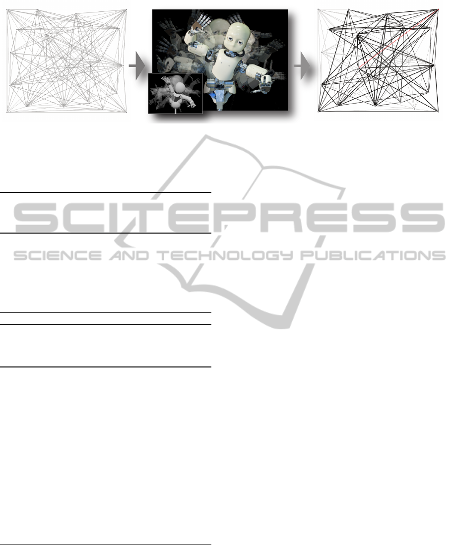
Figure 4: A Roadmap graph is built autonomously, online, by the iCub humanoid robot. Samples are connected optimistically
to their k nearest neighbors, yielding a Roadmap graph G(V, E) (left). The iCub explores the graph (center), and collision
detection is done by MoBeE (center inset). Infeasible edges are removed from the graph, which is thus adapted to the
physical constraints of the iCub. The feasible portion of the graph is shown in bold (right). The remaining non-bold edges are
unreachable, and the red edge represents the currently active motion.
Algorithm 5: SUPERVISE() is a thread that watches
incoming RPC commands from the Agent, storing the
“safe” pose q ∈ V before forwarding the command to
the hardware.
SUPERVISE() begin
while true do
if new RPC command arrived then
sa f ePose ← q
current
;
end
wait period;
end
end
Algorithm 6: REFLEX() interrupts the Agent when
the kinematic model collides unexpectedly, stopping
the robot, and rolling the state of the robot back
through the history.
REFLEX() begin
while true do
if robot model collides then
Disable filteredInterface;
Stop the robot;
poses ← history;
truncate poses at safePose;
foreach q ∈ poses do
sendPositionMove(q);
wait historyPeriod;
end
while checkMotionDone() 6= true do
wait period;
end
Enable filteredInterface;
end
end
end
in a common workspace. Finally we evaluate an in-
tegrated Sensor, Agent, Controller system, on a real-
world reaching task, using the iCub.
3.1 Adaptive Roadmap Planning
To evaluate the proposed Adaptive Roadmap Plan-
ning approach, we first carried out two experiments
related to roadmap construction and adaptation, re-
spectively.
In the first experiment, we choose 20 random sam-
ples in the configuration space of the iCub humanoid
robot, and optimistically construct a roadmap by con-
necting them to their 10 nearest neighbors (figure 4,
left), without verifying the feasibility of the result-
ing graph edges. The iCub then explores the graph
by planning and executing motions (figure 4, center).
The randomized vertex selection is biased toward ver-
tices with unexplored, adjacent edges. Running the
iCub at a conservative 10% of maximum speed, the
exploration process requires approximately 90 min-
utes to completely determine the feasible sub-graph.
We have carried out similar experiments with a num-
ber of different graphs, and we observe that the trans-
action based communication between Agent and Con-
troller works well in practice, and we are able to au-
tonomously construct roadmaps on-line while avoid-
ing self collisions.
Although the MoBeE infrastructure facilitates op-
timistic construction of the roadmap graph, we are
compelled to point out the following: Small, ran-
domly generated graphs often contain unreachable
vertices and edges (figure 4, right). These can usu-
ally be connected to the graph by construction, if the
map is grown incrementally, however a pruning step
would improve the “cleanliness” of our graphs in gen-
eral. Secondly, it is possible that a vertex has fea-
sible “in” edges, but no feasible “out” edges. Mov-
ing to these vertices causes the exploratory behavior
to get “stuck”. To facilitate motions away from such
partially-connected vertices, new edges (and possibly
vertices) must be constructed. Ultimately, to max-
TheModularBehavioralEnvironmentforHumanoidsandotherRobots(MoBeE)
309
imize the Agent’s constructive power, it should be
equipped with a single query Planner that can robustly
find paths back to the graph from partially connected
vertices.
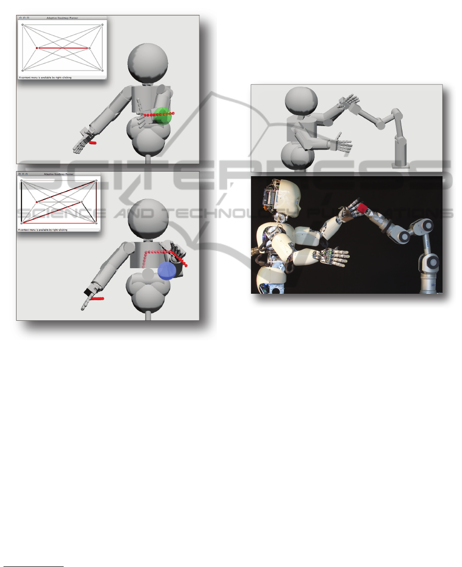
Figure 5: The iCub autonomously re-plans a motion to
move from one side of the ball to the other. If the ball is
not a solid object (top), the Agent moves the hand through
it. When the ball is suddenly made an obstacle (bottom),
the Agent quickly finds the path around it. The active plan
is shown with red edges in the inset graphs.
The second experiment is based on a very small
graph, which we have deliberately constructed, such
that there exist two different paths that move the hand
from one side of the ball to the other. The shorter
path causes the hand to pass through the ball, whereas
the longer path circumvents it. Initially, the model of
the ball is left out of collision detection computations
(figure 5, top, green ball), and the Agent prefers to
move the hand to the other side of the ball via the
shortest available path, moving the hand through the
ball. When we solidify the ball
7
(figure 5, bottom,
blue ball), the Agent quickly finds the alternative path
around it. This demonstrates that with the supervision
7
MoBeE supports on-the-fly editing of objects, includ-
ing collision checking behavior.
of MoBeE, our Agent can alter the topology of the
roadmap to adapt to a changing environment.
3.2 Learning a Sensor Module with
Multiple Robots
In this, the third experiment, we exploit the MoBeE
framework to develop a Sensor module to support vi-
sion, using a machine learning approach.
Figure 6: The iCub and Katana robots (botom) cooperate in
a shared workspace. Each robot is controlled via its own
Agent/Controller pair and the shared MoBeE framework
(top).
We use the Katana arm to place an object of in-
terest, in this case a children’s block, precisely at a
number of known 3-Space locations within the iCub’s
workspace (figure 6). Meanwhile, the iCub moves
about the object, seeing it from different angles, and
in this way, we build up a data set from which we learn
to map camera images to 3-Space locations, given
body states.
The modular architecture of the MoBeE frame-
work drastically facilitates the implementation of the
(rather complex) experimental setup required to do
this kind of multi-robot interaction. The kinematics
of the iCub and the Katana are loaded from XML
into a common model. The Controller described
above, which implements reflexive collision response,
is used for both robots. In order to produce the de-
sired training data however, the Katana and the iCub
require different Agents. The Katana’s Agent is very
simple. It just moves through a series of predeter-
mined poses, waiting at each one, such that the iCub
ICINCO2012-9thInternationalConferenceonInformaticsinControl,AutomationandRobotics
310

can observe the block. The iCub’s Agent is stochas-
tic. For each move of the Katana, the iCub assumes a
number of randomly selected poses, from which it ob-
serves the block. Occasionally, the two robot models
do collide, and the reflexive collision response safely
returns the physical robots to a previous configura-
tion. In order to accomplish this reliably, we must
only tune two parameters of the Controller, its control
frequency and the length of its history buffer. With
these set correctly for each robot (and with respect
to one another), the reflexive responses of both are
synchronous, and the stochastic collection of training
data runs robustly for hours.
This experiment demonstrates the following key
claims: MoBeE is robot independent, and can exploit
any device that can be controlled via YARP. It also
supports multiple interacting robots, and behavioral
components are portable and reusable thanks to their
weak coupling. So far, we have demonstrated three
uses of our reflexive Controller. In the first two ex-
periments we tested it with the Adaptive Roadmap
Planning Agent. In this experiment we tested it with
the scripted Katana Agent and also with the stochastic
image gathering Agent for the iCub. Moreover, since
MoBeE is completely transparent, it imposes no con-
straints on the Agent, and in fact the different Agents
mentioned were implemented by different developers,
some of whom had little or no knowledge of the Con-
troller.
3.3 A Real-world Reaching Task
This final experiment integrates the Adaptive
Roadmap Planning Agent, the Reflexive Controller,
and the machine learning based Sensor, to produce
reaches to real-world objects, using the iCub.
We use only objects that are known to the De-
tector, the cup in figure 8 for example. The Sensor
identifies and locates the objects of interest at reg-
ular intervals and sends RPC commands to update
the world model in MoBeE. Meanwhile, the Agent
queries MoBeE (again via RPC) for the state of the
salient object, plans a reach, and tries to execute it.
Of course the controller may intervene.
A task of this scale, requires that we use a much
larger roadmap than we have shown in the previous
experiments. Consider for a moment what such a
map should look like. Most of the robot configu-
rations associated with the vertices of the roadmap
graph should put the iCub’s hand at feasible pre-grasp
postures. If we intend to cover the approximately
1
2
m
2
of reachable table with pre-grap poses at, say, 1cm
resolution, we require 5, 000 vertices in the map. It
is impractical to construct such a map by hand. Ran-
Figure 7: A large roadmap is constructed by searching the
configuration space for a set of approximately 5,000 “in-
teresting” poses. The scattered dots in the robot model
(top-left) represent the position of the left hand as the robot
assumes the pose associated with each vertex in the map
(bottom-right).
Figure 8: The resulting pose after reaching to the cup us-
ing an integrated Sensor, Agent, Controller system with the
iCub robot. The inset (right) shows the iCub’s vision, over-
laid with the (red) output of an Detector module. The cup,
modeled as a cylinder, has been placed into the MoBeE
model (left) by a Locator module. The roadmap used to
plan the reach is pictured in figure 7.
dom sampling is also infeasible, and we must there-
fore search for our graph vertices more intelligently.
To find the vertices of the large roadmap, we em-
ploy a black-box optimization algorithm called Natu-
ral Evolution Strategies (NES) (Wierstra et al., 2008).
In order to constrain the optimization: Let q
home
be
some ergonomic rest position of our choosing, and let
q
i
, 0 < i ≤ 5, 000 represent the set of desirable pre-
grasp poses. Let p
h
(q
i
) be the position vector of the
hand in operational space, associated with a partic-
ular robot configuration. Similarly, let n
h
(q
i
) be the
palm normal. Let the table surface be represented by
the function f (x,y, z) = 0, let d(p
h
) represent the per-
pendicular distance between p
h
and f (x, y, z) = 0, and
let the scalar d
table
be the desired offset between the
palm and the table for pre-grasping purposes. Finally,
let the normal vector of the table surface be n
t
, ori-
TheModularBehavioralEnvironmentforHumanoidsandotherRobots(MoBeE)
311

ented toward the side of the table where we expect to
find suitable hand positions p
h
. We then constrain the
optimization as follows:
Minimize : |q
i
− q
home
| (1)
Minimize : |d(p
h
) − d
table
| (2)
Minimize : n
h
· n
t
(3)
Running NES on these constraints yields a single
q
i
. To build up a map, we require two more defini-
tions: Let q
∗
be the current best approximation of the
next map vertex, q
i+1
, and let d
hand
represent the de-
sired distance between the hand positions, p
h
(q
i
). We
then iteratively re-run NES, with the additional con-
straint:
Minimize : Argmin(|p
h
(q
∗
) − p
h
(q
i
)| − d
hand
) (4)
A typical result of this kind of iterative optimiza-
tion is shown in figure 7. We would like to reiter-
ate that we do not carry out collision detection com-
putations to verify the feasibility of the edges in the
map, but instead connect the map optimistically using
k nearest neighbor search. In this case k = 8. This
makes a lot of sense in light of the application. Since
the map consists of pre-grasp poses with the hand
above the table, there are very few infeasible edges.
Although it would clearly take a very long time to ex-
plore the entire map, controlling the hardware through
every edge, there is actually no reason to do so. In-
stead, we simply exploit the map optimistically and
greedily, generating reaches as necessary. When in-
feasible edges are found, for example when we bump
into the object we are trying to pre-grasp, we quickly
re-plan and adapt the map to the current world state.
The canonical Roadmap Planner would sample
every edge in the graph and do extensive collision de-
tection computations to verify the feasibility of each
motion whenever the world state changes. Lets briefly
consider how much time that would take. We have
5, 000 vertices at roughly 1cm resolution in opera-
tional space, with 8 edges per vertex, so we have
roughly 10cm of edge emanating from each vertex.
If we sample that at 1mm resolution, we have about
500, 000 poses for which we need to compute colli-
sion detection. The kinematic model within MoBeE,
when run offline, can compute collision detection for
iCub poses at about 1, 000Hz, if the workspace is de-
void of obstacles. Therefore we are talking about
roughly 10 minutes of offline computation to vali-
date the map every time the state of the workspace
changes.
This experiment demonstrates that MoBeE and
our Sensor, Agent, Controller behavioral decomposi-
tion, allow us to build and use a roadmap data struc-
ture for motion planning in a fundamentally differ-
ent way than the canonical Roadmap Planner does.
In running this and other similar experiments, we
observe that proposed Adaptive Roadmap Planning
works well in practice, generating reaches to objects
as pictured in figure 8. Moreover, owing to the mod-
ularity of the Sensor, Agent, Controller architecture,
we can easily modify the behavior with minimal de-
velopment overhead.
4 CONCLUSIONS
In this work, we have argued that most demonstra-
ble behaviors for modern complex robots, such as
humanoids, do not successfully integrate solutions to
key problems in Computer Vision, Motion Planning,
and Feedback Control. Furthermore, we hypothesized
that this lack of integration has limited the autonomy
and adaptiveness with which state of the art robots be-
have.
We view this to be primarily a software en-
gineering problem, and as a potential solution we
have introduced a novel behavioral decomposition
for humanoids and other complex robots, as well as
MoBeE, which constitutes the necessary software in-
frastructure to realize behaviors based on our decom-
position. Three loosely coupled modules, the Sen-
sor, the Agent and the Controller correspond to ab-
stract solutions to key problems in Computer Vision,
Motion Planning, and Feedback Control, respectively,
and MoBeE implements the hub and spokes architec-
ture that integrates the three to produce autonomous,
adaptive behaviors.
Furthermore, we have implemented an Agent
based on Roadmap Planning and a Controller that
simply tracks the inverse of the robot’s state history,
resulting in a family of adaptive roadmap planning
behaviors. Although the constituent modules derive
from “off the shelf” solutions from Motion Planning
and Feedback Control, our integrated behaviors, of-
fer drastically improved autonomy and adaptiveness
over the canonical Roadmap Planner, which we have
shown in several demonstrative experiments.
To highlight the usefulness of the modular experi-
mental framework provided by MoBeE, we have im-
plemented two additional Agent modules, which were
used in conjunction with the same reactive Controller
on two different robots. As a result, the iCub hu-
manoid and the Katana arm were able to operate in a
shared workspace to autonomously generate training
data, which we then used to develop a Sensor module
ICINCO2012-9thInternationalConferenceonInformaticsinControl,AutomationandRobotics
312

for object localization.
Finally, the Sensor, the Adaptive Roadmap Plan-
ning Agent, and the Controller were integrated to
demonstrate a real-world reaching behavior with the
iCub. We conclude that careful software engineer-
ing and the successful integration of key Computer
Vision, Motion Planning, and Feedback Control so-
lutions drastically facilitates the synthesis of au-
tonomous, adaptive behaviors.
ACKNOWLEDGEMENTS
This research was supported by the EU Project IM-
CLeVeR, contract no. FP7-IST-IP-231722. The au-
thors would also like to thank Tobias Glasmachers for
his valuable contributions to the code-base.
REFERENCES
Brooks, R. (1991). Intelligence without representation. Ar-
tificial intelligence, 47(1):139–159.
Denavit, J. and Hartenberg, R. (1955). A kinematic notation
for lower-pair mechanisms based on matrices. Trans.
of the ASME. Journal of Applied Mechanics, 22:215–
221.
Fitzpatrick, P., Metta, G., and Natale, L. (2008). Towards
long-lived robot genes. Robotics and Autonomous
Systems, 56(1):29–45.
Forsyth, D. and Ponce, J. (2002). Computer vision: a mod-
ern approach. Prentice Hall Professional Technical
Reference.
Franklin, G., Powell, J., and Emami-Naeini (1994). Feed-
back control of dynamic systems, volume 2. Addison-
Wesley Reading, MA.
Gupta, K. (1986). Kinematic analysis of manipulators using
the zero reference position description. The Interna-
tional Journal of Robotics Research, 5(2):5.
Hartley, R. and Zisserman, A. (2000). Multiple view geom-
etry in computer vision, volume 2. Cambridge Univ
Press.
Jackson, J. (2007). Microsoft robotics studio: A technical
introduction. IEEE Robotics & Automation Magazine,
14(4):82–87.
Kaufmann, G. (2010). A flexible and safe environment for
robotic experiments : a sandbox and testbed for exper-
iments intended for the humanoid robot icub. Master’s
thesis, Universit
`
a della Svizzera italiana (USI).
Kazerounian, K., Latif, K., Alvarado, C., et al. (2005a).
Protofold: A successive kinetostatic compliance
method for protein conformation prediction. Journal
of Mechanical Design, 127:712.
Kazerounian, K., Latif, K., Rodriguez, K., Alvarado, C.,
et al. (2005b). Nano-kinematics for analysis of protein
molecules. Journal of Mechanical Design, 127:699.
LaValle, S. (2006). Planning algorithms. Cambridge Univ
Pr.
Metta, G., Fitzpatrick, P., and Natale, L. (2006). YARP:
Yet Another Robot Platform. International Journal of
Advanced Robotic Systems, 3(1).
Quigley, M., Gerkey, B., Conley, K., Faust, J., Foote, T.,
Leibs, J., Berger, E., Wheeler, R., and Ng, A. (2009).
ROS: an open-source Robot Operating System. In In-
ternational Conference on Robotics and Automation,
Open-Source Software workshop.
The Boost Graph Library (accessed 2012). Bgl, the boost
graph library. url=http://www.boost.org/libs/graph/.
The CGAL Project (accessed 2012). Cgal, the com-
putational geometry algorithms library. url=http://
www.cgal.org/.
van den Bergen, G. (2004). Collision detection in interac-
tive 3D environments. Morgan Kaufmann.
Wierstra, D., Schaul, T., Peters, J., and Schmidhu-
ber, J. (2008). Natural evolution strategies. In
Evolutionary Computation, 2008. CEC 2008.(IEEE
World Congress on Computational Intelligence).
IEEE Congress on, pages 3381–3387. IEEE.
TheModularBehavioralEnvironmentforHumanoidsandotherRobots(MoBeE)
313
