
SELF-ADAPTATION IN AUTOMOTIVE EMBEDDED SYSTEMS
USING A MULTI-LAYERED CONTROL APPROACH
Marc Zeller and Christian Prehofer
Fraunhofer Institute for Communication Systems ESK, Hansastrasse 32, 80686 Munich, Germany
Keywords:
Self-adaptation, Automotive, Control Architecture, Networked Embedded Systems.
Abstract:
In this work, we present an approach for self-adaptation in automotive embedded systems using a hierarchical,
multi-layered control approach. We model automotive systems as a set of constraints and define a hierarchy
of control loops based on different criteria. Adaptations are performed at first locally on a lower layer of the
architecture. If this fails due to the restricted scope of the control cycle, the next higher layer is in charge
of finding a suitable adaptation. We compare different options regarding responsibility split in multi-layered
control and a version with centralized control option, in a self-healing scenario with a setup adopted from
automotive in-vehicle networks. We show that a multi-layer control architecture has clear performance benefits
over a central control, even though all layers work on the same set of constraints. Furthermore, we show that
a responsibility split w.r.t. network topology is preferable over a functional split.
1 INTRODUCTION
There has been considerable work on self-adaptive
systems which can reconfigure their software config-
uration at runtime (Kramer and Magee, 1985; Oreizy
et al., 1998; Georgiadis et al., 2002). However, apply-
ing these techniques to networked, embedded systems
poses several new problems due to limitations and
reliability requirements of embedded systems (Zeller
et al., 2011b). In particular, we focus on automotive
embedded systems, where the main constraints are
• limited memory resources,
• heterogeneous hardware platforms,
• different sub-networks connected by a gateway,
• various requirements of different functionalities,
• high demand on safety and reliability.
The focus of this paper is on self-adaptation in auto-
motive embedded systems using a multi-layered con-
trol approach implemented by multi-layered control
architecture. Today’s automobiles consist of an in-
creasing number of interconnected electronic devices
- so-called Electronic Control Units (ECUs) - which
realize most functionalities of the car by software.
This networked embedded system keeps the vehicle
running by controlling the engine and the breaks, pro-
vides active safety features (e.g. anti-lock breaking
system), makes driving more convenient and enter-
tains the passengers with a large number of informa-
tion and comfort services (e.g. air conditioning, au-
dio player). Especially, modern driver assistance sys-
tems, which distribute their functionality over several
components, increase the complexity of today’s ve-
hicular embedded systems enormously. Managing to-
day’s vehicle software systems, means managing over
2,000 software components, running on up to 100
ECUs (Venkatesh Prasad et al., 2010).
Enhancing today’s automotive embedded systems
with self-adaptation provides a promising solution for
the current challenges in automotive embedded sys-
tems (Weiss et al., 2009). Self-* properties like self-
configuration, self-healing, self-optimization or self-
protection (Kephart and Chess, 2003) improve the
scalability, robustness and flexibility of the system
(Weiss et al., 2011). With the size of automotive
systems, it becomes difficult to calculate all config-
urations and all failure cases in advance. Hence, the
adaptation of the system may have to be calculated
during runtime. In this work, we focus on the adap-
tation control of the system after the breakdown of a
hardware platform. The actual reconfiguration of the
system itself is not the focus here, and can for instance
be performed during a (partial) restart of the system.
For realizing systems with these self-managing
capabilities a control component is needed (M¨uhl
et al., 2007). This external component supervises the
459
Zeller M. and Prehofer C. (2012).
SELF-ADAPTATION IN AUTOMOTIVE EMBEDDED SYSTEMS USING A MULTI-LAYERED CONTROL APPROACH.
In Proceedings of the 2nd International Conference on Pervasive Embedded Computing and Communication Systems, pages 459-468
DOI: 10.5220/0003942304590468
Copyright
c
SciTePress

system and initiates the adaptation during runtime us-
ing closed feedback-loops (so-called control loops)
(Brun et al., 2009). In the Autonomic Computing
(AC) paradigm the elements of the system are man-
aged by control loops based on the so-called MAPE-
K cycle (Horn, 2001) which optimizes the operation
of the supervised elements and enables the realization
of self-* properties. Such a control loop continuously
Monitors and Analyzes the system and its environ-
ment. Based on this information it Plans the next
steps and Executes the planned actions. The differ-
ent phases have access to a common Knowledge base
which provides information about the supervised ele-
ments or system.
Especially for automotivesystems with various re-
quirements and constraints, enabling self-adaptation
and building a control architecture is a challenging
task. Different aspects of the automotive system like
safety issues must be considered by the control com-
ponents appropriately. Furthermore, the control archi-
tecture has to react quickly to changing conditions, ei-
ther from inside the system (e.g. hardware or software
failures) or from outside of the system (e.g. changing
environmental conditions).
The control component of a self-adaptive system
can be realized in different ways. Either a single cen-
tralized control entity may realize the adaptation of a
software system, or multiple control components may
realize the adaptation of composite of software sys-
tems in a decentralized manner (Cheng et al., 2009).
While centralized control may not be efficient for re-
alizing adaptation in large, complex, and heteroge-
neous systems (e.g. automotive embedded systems),
fully decentralized approaches may lead to a coordi-
nation overhead within the system.
An alternative are hierarchical multi-layered con-
trol architectures, as discussed in (Horn, 2001), where
multiple control loops cooperate to achieve adapta-
tion. In this paper, we model such automotive sys-
tems using a set of constraints as introduced in (Zeller
et al., 2011a). Based on this, we can define the opera-
tion and responsibility area of each local control cycle
in the hierarchy based on different functional criteria.
Even thoughall control cycles work on the same set of
constrains, local responsibility means that only some
variables can be controlled and the others are fixed.
This also means that some constraints are out of scope
for some local control cycles. We compare different
options, both regarding different splits of responsibil-
ity as well as multi-layered control versus centralized
control.
In summary, the main contributions of this paper
are as follows:
• We introduce different multi-layered control ar-
chitectures for automotive embedded systems
which hierarchically enforce system requirements
on several layers. Therefore, the software compo-
nents of the system are clustered based on differ-
ent functional criteria.
• We compare these multi-layered architectures in a
self-healing scenario with realistic setups of up to
100 ECUs. It is shown that local repair based on
a layered control architecture in such a system is
more efficient than a pure central approach. Sec-
ondly, it shows that a responsibility split based on
locality w.r.t. network topology performs better
than a split regarding functional areas.
The structure of this paper is as follows: In Sec-
tion 2 a brief introduction to automotive embedded
systems is given. Section 3 briefly describes our ap-
proach for a hierarchical, multi-layered control archi-
tecture. Afterwards, we propose a concrete multi-
layered control architecture for self-adaptive automo-
tive software system. In Section 5, we outline how
to realize self-adaptation during runtime using our
multi-layered control architecture. Section 6 presents
the results of the experiments which we performed to
compare our approach with a centralized architecture.
Section 7 discusses related work.
2 AUTOMOTIVE EMBEDDED
SYSTEMS
An automotive embedded system is a distributed real-
time system with heterogeneous hardware platforms
(ECUs) interconnected by different network buses
(Venkatesh Prasad et al., 2010). Moreover, the au-
tomotive embedded system consists of various func-
tionalities which are implemented in software and
which must satisfy different requirements.
Thereby, an automotive embedded system A con-
sists of a set of inputs I (sensors), a set of functionali-
ties F = {f
1
, ..., f
n
} (features), and a set of outputs O
(actuators). The set of functionalities is realized by a
set of software components SW, where each feature f
i
is implemented by a set of software components SW
f
i
with SW
f
i
⊂ SW. Software components, sensors and
actuators are connected to each other in a specified
way. This so-called function network can be repre-
sented by a directed graph G
f
(V
f
, E
f
). The vertices
V
f
represent software components, actuators or sen-
sors. The directed edges E
f
indicate a data flow from
one vertex to another by sending messages. Each ver-
tex may have multiple incoming edges and multiple
outgoing edges.
The so-called system configuration c describes
PECCS 2012 - International Conference on Pervasive and Embedded Computing and Communication Systems
460
the allocation of the software components (SW =
{s
1
, ..., s
n
}) to the available ECUs (P = {p
1
, ..., p
m
})
at time t
c(t) : SW → P = {0, 1}
n×m
(1)
with n · m variables x
i, j
. If the software component s
i
is assigned to ECU p
j
, then x
i, j
= 1, else it is 0. The
allocation of a specific software component s
i
∈ SW
is represented by j :
j (s
i
) = p
j
, p
j
∈ P (2)
Moreover, A consists of a set of constraints Y =
{y
1
, ..., y
p
} which represent the requirements of the
system during runtime and enable the definition of
valid allocations. These constraints are defined in
(Zeller et al., 2011a). Abstractly, a linear constraint
y
k
∈ Y is defined as a Boolean formula:
y
k
=
n
å
i=1
m
å
j=1
a
i, j
x
i, j
!
◦ b → {true, false} (3)
with the Boolean literals x
i, j
∈ {0, 1} which repre-
sent the allocation of the software component s
i
to the
ECU p
j
, the coefficients a
i, j
, b ∈ R, and the operator
◦ ∈ {<, ≤, =, ≥, >}.
Typical constraints in terms of automotivesystems
concern hardware platform resources (e.g. volatile,
non-volatile memory), network resources (e.g. band-
width), task dependencies, task schedulability, tim-
ing or the network topology. A detailed descrip-
tion of these of equations, called system constraints,
which define valid system configurations under real-
time constraints, can be found in (Zeller et al., 2011a).
This set of equations is optimized to be solved effi-
ciently during runtime in order to enable the compu-
tation of valid system configurations in an adaptive
system in reasonable time, as shown in (Zeller et al.,
2011a).
3 HIERARCHICAL,
MULTI-LAYERED CONTROL
ARCHITECTURE
In this section, we give a brief overview over hierar-
chical multi-layered control architectures. For details
we refer to (Horn, 2001; Zeller et al., 2009).
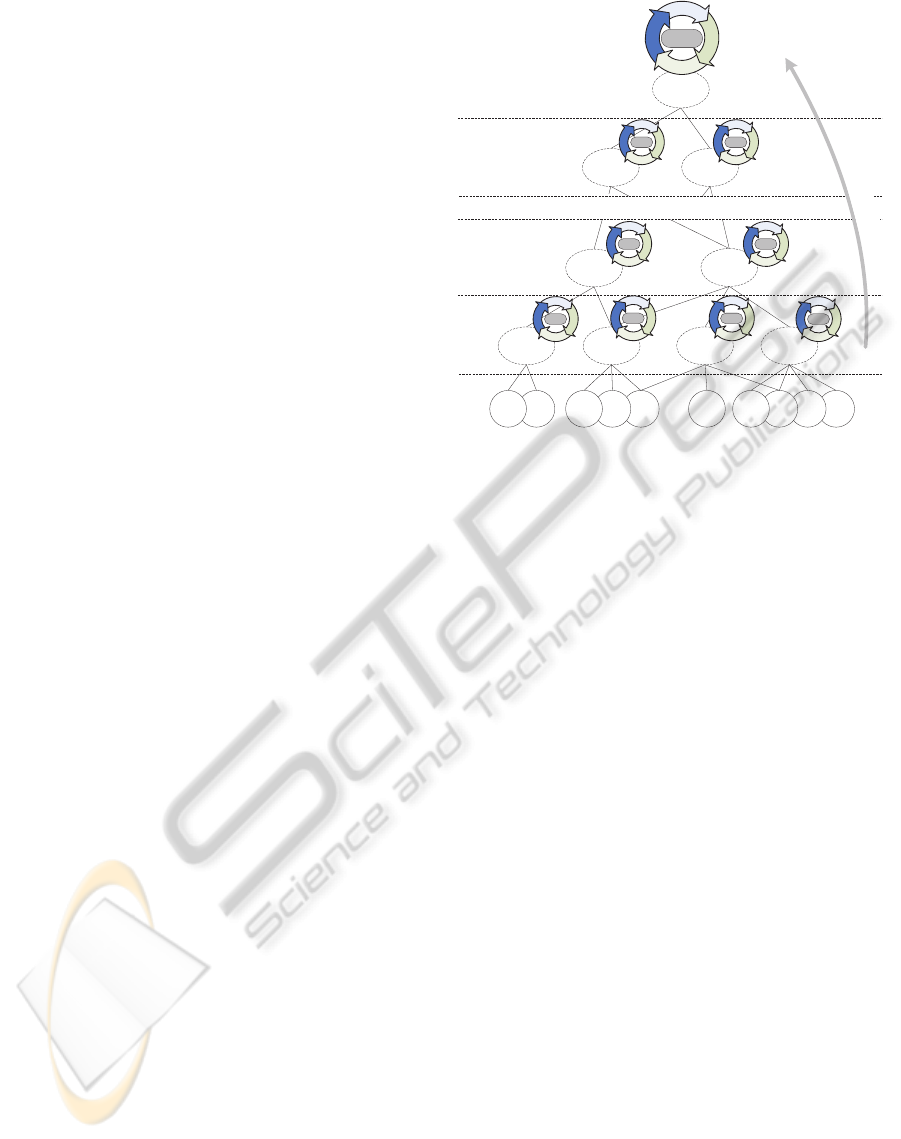
To cope with the complexity of modern auto-
motive embedded systems, we propose a hierarchi-
cal, multi-layered control architecture (see Figure 1).
Resources for enforcing adaptations at runtime are
scarce but absolutely inevitable for realizing self-*
properties. Therefore, a divide-and-conquer strategy
Cluster A Cluster B Cluster C Cluster D
Cluster F
Cluster Q
Cluster N Cluster P
Cluster E
...
Layer n
(Top Layer)
Layer 1 Layer 2 Layer n-1
...
Monitor
Analyse
Plan
Execute
Knowledge
Base
I
n
f
o
m
a
t
i
o
n
F
l
o
w
1
S
2
S
3
S
4
S
5
S
n
S
n-1
S
n-4
S
n-3
S
n-2
S
...
Figure 1: Hierarchical, multi-layered control architecture.
can be applied during design which partitions the au-
tomotive embedded system into smaller entities - so-
called clusters.
A cluster cl is defined by a set of r software com-
ponents {s
1
, ..., s
r
} = SW
cl
⊆ SW. The current cluster
configuration c
cl
(t) describes the current allocation
j
cl
of the software components SW
cl
to the available
ECUs at the time t according to Equation 1.
Repeated partitioning of the automotive embed-
ded system results in a hierarchy of clusters, repre-
senting the entire system. Thereby, each cluster has
at least one parent cluster and any number of child
clusters. The top level of this hierarchy consists of
exactly one cluster. Each cluster within the hierarchy
is controlled by its own control loop, thus building a
multi-layered control architecture. A control loop is
an external component which is not included within
the cluster itself. It is supervising and controlling
(adapting) the clustered elements during runtime, so
that the constraints Y are satisfied during runtime (see
Section 5).
Due to the repeated segmentation of the automo-
tive embedded system, the clusters on the lowest lay-
ers of the control architecture are relatively small.
They consist of only a few software components. Due
to the individual implementation of the control loops
at the lowest layers, the control architecture can be
tailored individually for the needs of specific func-
tionalities or sub-systems of the automotive embed-
ded system (e.g. safety-critical X-by-wire systems).
As a drawback, the clusters on the lower layers have
a restricted local scope and are not always capable of
determining a new, valid cluster configuration which
SELF-ADAPTATION IN AUTOMOTIVE EMBEDDED SYSTEMS USING A MULTI-LAYERED CONTROL
APPROACH
461

satisfies all given requirements.
At the higher layers, the number of software com-
ponents included in a cluster, which must be con-
trolled, is growing. Thus, the possibilities of deter-
mining a valid cluster configuration increases but also
the complexity of determining a valid configuration is
rising with the number of software components which
are considered.
At the top layer,a single root cluster represents the
top element in the hierarchy. It has a global view of
the system and supervises the entire automotive em-
bedded system during runtime with all its predefined
requirements.
During runtime, the automotive embedded system
is supervised by a hierarchy of multiple MAPE-K cy-
cles which adapt the system in response to changes
within the system or in the system’s environment.
Based on an individual knowledge base, each MAPE-
K cycle manages its cluster in four stages:
Monitor: Each control component within the control
architecture collects, aggregates and filters spe-
cific parameters of their managed elements (soft-
ware components within the cluster). The param-
eters which need to be monitored are given by
the requirements which can by supervised by the
scope of the control loop.
Analyze: During this stage the monitored data are
analyzed and compared to the available data in the
knowledge base of the control loop. Each control
instance evaluates if the predefined requirements,
which it supervises, are currently satisfied.
Plan: The plan stage provides mechanisms that cre-
ate or compose a set of actions to adapt the su-
pervised part of the system. In the context of au-
tomotive embedded systems, the planning stage
determines a new cluster configuration which ful-
fills all predefined requirements (see (Zeller et al.,
2011a)).
Execute: During this stage the planned actions are
executed. In our case, each control loop adapts
the allocation of the software components which
are included in its cluster in the planned way.
Based on the hierarchy of MAPE-K cycles within our
multi-layered control architecture it is possible to en-
hance the automotiveembedded system by adaptation
and self-* properties.
4 MULTI-LAYERED CONTROL
ARCHITECTURE FOR
AUTOMOTIVE EMBEDDED
SYSTEMS
In this section, we present two variants of the hierar-
chical, multi-layered control architecture for automo-
tive embedded systems.
The most intuitive approach is a topology-oriented
structuring according to the network topology of to-
day’s in-vehicle networks (see Figure 2). For this
purpose, the automotive embedded system - Vehi-
cle Cluster on the top layer of the hierarchy - is di-
vided into different clusters according to the physical
sub-networks within the in-vehicle network which re-
sult from the segmentation of the car’s functionalities
into functional domains (e.g. power-train, infotain-
ment, chassis, comfort etc.). Thereby, five so-called
Network Clusters are created which include all soft-
ware components defined for a specific sub-network
(domain). At the next layer of the hierarchy, each
Network Cluster is split up according to the physi-
cal hardware platforms connected to the sub-network.
The resulting Platform Clusters represent the soft-
ware components which are initially allocated to a
specific ECU and control them by its own MAPE-K
cycle. Since this control loop must be able to detect
if the specific ECU is faulty and must adapt the al-
location of the ECU’s software components, it is im-
plemented on one of the other ECUs within the sub-
network.
ZĂĚĂƌ^ĞŶƐŽƌ
ĂƚĂ
!"
-+
#3
-+
#3#
-+
#32
-+
#3
'
&
( )
$&
-+
#3
,D/sŝĞǁ
****** ******
$"+
******
ĐĐĞůĞƌĂƚĞ
Ăƌ
,
Figure 2: Multi-layered control architecture for automotive
embedded systems (variant 1, topology-oriented).
Due to the increasing interconnection of the dif-
ferent vehicle domains (e.g. by advanced driver assis-
tance systems), this kind of partitioning of automotive
embedded systems may become less suitable for the
realization of a multi-layered control architecture for
automotive embedded systems. In other words, a lo-
cal control loop responsible for a sub-network may
not be able to find a local solution due to dependen-
PECCS 2012 - International Conference on Pervasive and Embedded Computing and Communication Systems
462

cies with other domains.
Another approach for a control architecture for au-
tomotive embedded systems is based on a function-
oriented structuring of the in-vehicle network (cp.
(Broy et al., 2011)). Thereby, the automotive em-
bedded system is divided into five so-called Safety
Clusters according to the Safety Integrity Levels (SIL)
0-4 defined by (ICE, 1998) or by the Automotive
Safety Integrity Levels (ASIL) A-D as well as Qual-
ity Management (QM) defined by (ISO, 2005) which
are used to classify the safety requirements of the
car’s functionalities (see Figure 3). Thus, function-
alities with different safety requirements are moni-
tored and controlled by specifically adjusted mecha-
nisms. Safety-critical functionalities are reconfigured
using adequate techniques which consider the func-
tions’ safety requirements, while other functionalities
are adapted during runtime by other, more appropri-
ate techniques. At the next layer of the hierarchy, each
Safety Cluster is split up according to the functional-
ities included into the vehicle’s domain. Each of the
resulting Feature Clusters represents a functionality
of the automobile which is realized by software and
controls the functionalities’ software components by
its own MAPE-K cycle. This represents the logical
structure of the automotive embedded system. Hence,
interdependencies between different clusters due to
interconnected sub-networks may be avoided.
Radar
Sensor Data
Central Door
Looking
Control
Vehicle Cluster
Safety Cluster
(SIL 3 / ASIL C)
Safety Cluster
(SIL 4 / ASIL D)
Safety Cluster
(SIL 0 / QM)
Feature Cluster
(Engine Control)
Feature Cluster
(ACC)
Feature Cluster
(Keyless Entry)
Feature Cluster
(Auxiliary Input)
Layer 3
(Top Layer)
Layer 1 Layer 2
Safety Cluster
(SIL 1 / ASIL A)
Feature Cluster
(Parking Assistant)
HMI View
Safety Cluster
(SIL 2 / ASIL B)
Accelerate
Car
Longitudinal
Controller
Figure 3: Multi-layered control architecture for automotive
embedded systems (variant 2, function-oriented).
In all these approaches the so-called Vehicle Clus-
ter forms the top layer of the hierarchical, multi-
layered control architecture. This cluster includes
all software components of the automotive embedded
system and its MAPE-K cycle has a global view of
the supervised system.
By using a hierarchical, multi-layered control ar-
chitecture, self-adaptation and different self-* prop-
erties can be realized while considering the spe-
cific nature of today’s automotive embedded sys-
tems. Thereby, the various requirements of these sys-
tems are monitored by several control components
(MAPE-K cycles) which are organized hierarchically.
Each MAPE-K cycle adapts the specific part of the
networked embedded system which it supervises.
In the following chapter, we describe how self-
adaptation is realized in automotive embedded sys-
tems using the multi-layered control approach.
5 SELF-ADAPTATION USING
THE MULTI-LAYERED
CONTROL ARCHITECTURE
In the following, we discuss the operation of multi-
layered control architectures for our setting with a
global set of system constraints. The aim of our
hierarchical, multi-layered control architecture is to
preserve all predefined requirements of the automo-
tive embedded system during runtime. Thereby, the
proper system behavior of the automotive embedded
system is guaranteed (see (Zeller et al., 2011b)). In
our approach, each MAPE-K cycle within the hierar-
chy enforces all the requirements specified in the de-
sign, which are represented in form of linear, Boolean
(in-)equations (see see (Zeller et al., 2011a)). If any of
the predefined requirements is not satisfied anymore
during runtime (e.g. caused by the breakdown of a
hardware platform), the configuration of the system c
is adapted to meet these constraints, if possible.
To enable a fast adaptation of the system dur-
ing runtime, adaptations are performed on the low-
est layer of the hierarchy by the cluster which detects
the cause for the adaptation. Since all system con-
straints are considered by each control loop within the
hierarchical, multi-layered control architecture, each
MAPE-K cycle - even on the lowest layer of the hier-
archy - is able to determine a new, valid system con-
figuration. However, the different control cycles have
different scope - hence the set of free variables is re-
stricted to the local scope. In other words, the local
control cycles are in charge of the placement of the
software components of their cluster.
Only if a cluster was not able to reach a new valid
cluster configuration, its parent cluster takes over the
adaptation process. The root cluster (Vehicle Cluster
in Section 4) is only involved in the adaptation pro-
cess as the last instance. Since the root cluster has
the global view and knowledge of the entire system,
it is always capable of reaching a new valid system
configuration – if one exits.
In the best case, the adaptation of the system is
performed by the control loop of one single cluster. In
the worst case, up to n control loops are involved in
the process of adaptation within an n-layered control
architecture. Thereby, constraint checks may be per-
SELF-ADAPTATION IN AUTOMOTIVE EMBEDDED SYSTEMS USING A MULTI-LAYERED CONTROL
APPROACH
463
formed multiple times until a new, valid system con-
figuration is found. This results in unnecessary com-
putation overhead – unless a solution is found on the
lower layers. On the other hand, on the top level, new
placements for all components are to be determined,
which is much more complex than solving equations
on a lower layer of the hierarchy. For the local scope,
only a limited, local number of placements are to be
determined. Furthermore, on the local scope, equa-
tions may be trivially true for a specific configuration
if they are not affected by the free variables of this
control cycle.
In the following, we aim to compare the differ-
ent versions of the hierarchical control architecture
with a central control solution. Thus, we have a trade-
off between finding solutions locally with lower cost,
but possibly with repeated attempts on different lay-
ers, versus a single control loop with a higher cost.
Clearly, if the hierarchical solution has to resort to the
top layer frequently, the centralized solution will be
more efficient.
Control loops at the same layer of the control ar-
chitecture shall not interfere with each other in or-
der to avoid oscillation during adaptation - hence
only one of them can be active at a time. In other
words, they must be synchronized/coordinated by a
dedicated synchronization mechanism to avoid that
several control components adapt the same part of
the system simultaneously (see (Lemos et al., 2011)).
This needs to be ensured, typically by the next layer.
During the ”normal” operation of the system
(monitoring and analysis of the correctly working au-
tomotive system) no synchronization is required and
hence no additional communicationbetween different
control loops within the multi-layered control archi-
tecture is performed.
6 EVALUATION
In this section, we illustrate the potential benefits of
our approach of a hierarchical, multi-layered control
architecture for realizing self-adaptation in automo-
tive embedded systems (see Section 4) w.r.t. effi-
ciency of determining a new, valid system configura-
tion in case of an ECU breakdown (self-healing sce-
nario). At first, an initial assignment of software com-
ponents to hardware is determined. After this, the
adaptation of the system is triggered by simulating the
breakdown of a randomly selected ECU.
6.1 Evaluation Setup
In our experiments, we simulate the typical
embedded systems of modern automobiles (see
(Venkatesh Prasad et al., 2010)). Therefore, we use
various setups representing different sizes and vari-
ants of automotive in-vehicle networks (see Table 1).
While the ratio between the number of software com-
ponents and the number of ECUs is fixed in the first
setups (1.1 - 1.9), we also perform experiments with
setups where this ratio is variable (setup 2.1 - 2.10).
For all experiments, we assume that each feature of
the vehicle consists of about 8 software components
as well as a number of sensors and actuators. More-
over, for half of the features an end-to-end timing
chain is defined consisting of one sensor input, up to 8
software components, and one actuator. The volatile
and the non-volatile memory requirements of each
ECU are represented as resource constraints. In our
experiments, the in-vehicle network consists of three
different kinds of hardware platforms. Each software
component can only be executed on one kind of hard-
ware platform (cf. (Zeller et al., 2011a)). Thus, each
software component can be allocated on about 33%
of the vehicles’ ECUs.
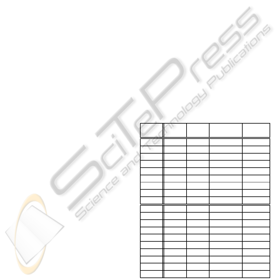
Table 1: Experimental setups.
Setup ECUs Func- Sensors / Subnet-
tions Actuators works
1.1 20 500 40/40 4
1.2 30 750 50/50 4
1.3 40 1000 60/60 5
1.4 50 1250 70/70 5
1.5 60 1500 80/80 8
1.6 70 1750 90/90 8
1.7 80 2000 100/100 8
1.8 90 2250 110/110 8
1.9 100 2500 120/120 8
2.1 40 200 60/60 5
2.2 40 400 60/60 5
2.3 40 600 60/60 5
2.4 40 800 60/60 5
2.5 40 1000 60/60 5
2.6 40 1200 60/60 5
2.7 40 1400 60/60 5
2.8 40 1600 60/60 5
2.9 40 1800 60/60 5
2.10 40 2000 60/60 5
For reference, we list the number of constraints
and literals needed to solve the SAT problem for the
given setups in table 2 (see (Zeller et al., 2011a)).
PECCS 2012 - International Conference on Pervasive and Embedded Computing and Communication Systems
464
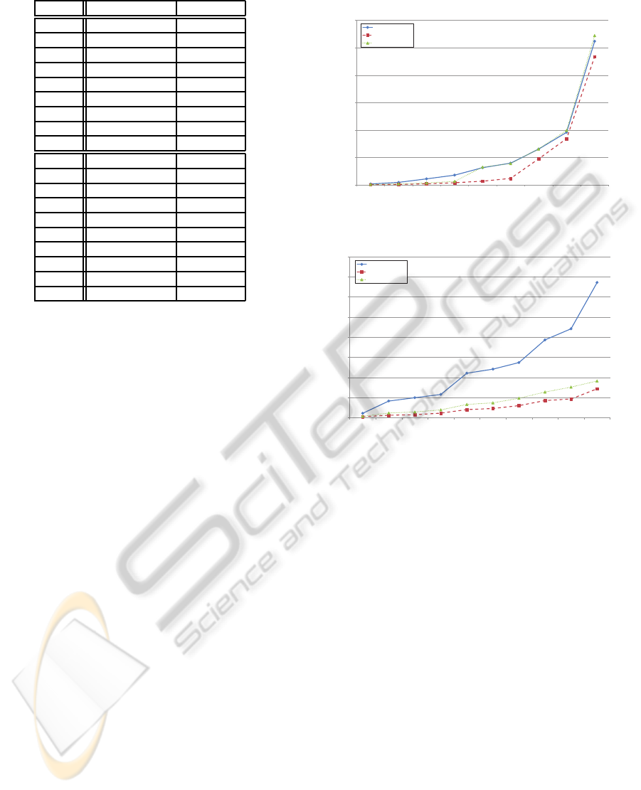
Table 2: Size of the set of system constraints.
Setup # Constraints # Literals
1.1 7,599 60,877
1.2 20,047 197,385
1.3 33,040 397,584
1.4 52,658 781,281
1.5 65,773 1,154,150
1.6 85,081 1,689,251
1.7 126,877 2,771,502
1.8 138,641 3,393,508
1.9 174,434 4,580,388
2.1 6,746 77,396
2.2 12,801 156,798
2.3 17,220 217,867
2.4 27,899 338,935
2.5 33,040 397,584
2.6 35,516 435,196
2.7 45,021 539,373
2.8 54,239 659,452
2.9 60,376 770,882
2.10 69,218 877,051
All values for ECUs, interconnection networks,
software components and sensors/actuators are ran-
domly chosen from a typical set of automotive pa-
rameters and uniformly distributed in the previously
given range.
For our experiments, the concrete control archi-
tecture variants for automotive embedded systems
outlined in Section 4 are implemented. Furthermore,
a centralized control architecture (similar to (Dinkel
and Baumgarten, 2007)) is implemented to compare
our multi-layered approach with this state-of-the-art
approach. According to (Zeller et al., 2011a) the SAT-
solver SAT4J (SAT4J, 2009) is used in all our ex-
periments to determine a valid allocation of software
components to ECUs within each MAPE-K cycle.
For each setup in Table 1, we perform tests with
each variant for the control architecture 10 times and
compare the average effort to determine a new valid
system configuration due to very small confidence
intervals (less than 10%). All experiments are per-
formed on an embedded platform with an Intel Atom
Processor @1.6 GHz and 1.5 GByte RAM (reference
platform for the next generation in-vehicle infotain-
ment systems).
6.2 Results
Figure 4 and 5 show the results of the experiments
which are performed with the previously described
variants of automotive embedded systems (see Table
1). In all experiments, we have measured the time
needed to determine a new, valid allocation of soft-
ware components after an ECU breakdown occurred
(self-healing scenario).
0
20
40
60
80
100
120
1.1 1.2 1.3 1.4 1.5 1.6 1.7 1.8 1.9
Time in sec
Centralized
3-Layered (variant 1)
3-Layered (variant 2)
Figure 4: Time needed to determine a new, valid system
configuration (Setup 1.1.-1.9).
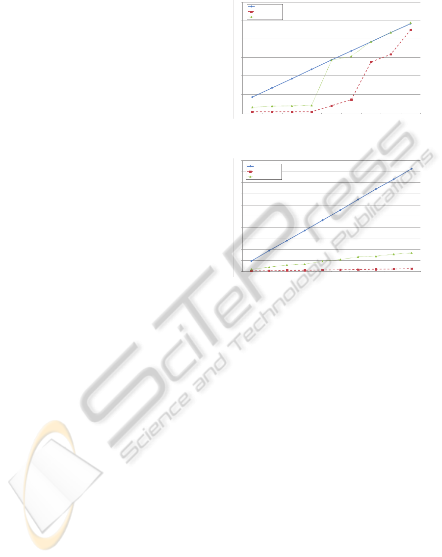
0
2
4
6
8
10
12
14
16
2.1 2.2 2.3 2.4 2.5 2.6 2.7 2.8 2.9 2.10
Time in sec
Centralized
3-Layered (variant 1)
3-Layered (variant 2)
Figure 5: Time needed to determine a new, valid system
configuration (Setup 2.1-2.10).
This result shows that when using one of the
hierarchical, multi-layered control architectures de-
scribed in Section 4, less computation time is needed
until a new valid system configuration is found, than
using a centralized control architecture with one sin-
gle control loop. For the setups 1.1-1.9 the differ-
ence between the centralized approach and the vari-
ant 2 (function-oriented) of our approach (see Figure
3) is quite small, especially for larger automotive in-
vehicle networks. But using the variant 1 (topology-
oriented) of the hierarchical, multi-layered control ar-
chitecture (see Figure 2), a significant performance
optimization is reached. For the setups 2.1-2.10 sig-
nificant optimization of the time needed to determine
a new, valid system configuration is reached by using
our hierarchical, multi-layered approach for control-
ling the automotive embedded systems. The differ-
ence between the two variants for the realization of a
multi-layered control architecture is quite small. Yet
the topology-oriented variant is performing better in
all our experiments.
The results of our experiments clearly show that
the complexity of realizing self-adaptation in automo-
tive embedded systems can be reduced significantly
SELF-ADAPTATION IN AUTOMOTIVE EMBEDDED SYSTEMS USING A MULTI-LAYERED CONTROL
APPROACH
465
by using our hierarchical, multi-layered control archi-
tecture. Furthermore, we also see that the topology-
oriented variant is significantly better in most cases
than variant 2, which clusters along the functional
entities. This means in case of an ECU failure, the
variant which considers solutions based on the lo-
cal network has better chances than the second vari-
ant, which considers solutions based on functionality.
While solutions based on functionality are more natu-
ral regarding the functional dependencies, there is the
risk that a CPU failure may affect several functional
categories - hence a local repair by one control cycle
is not possible.
This is also supported by the different results for
the setup 1.1-1.9 and 2.1-2.10. Here the topology-
oriented variant of the multi-layered control archi-
tecture is significantly better compared to function-
oriented variant for setups 2.1-2.10, while both are
closer in most experiments in setup 1.1-1.9 (except
1.5-1.7). Furthermore, both variants of the hierar-
chical, multi-layered control architecture are signif-
icantly better than the centralized approach for setup
2.1-2.10. Our multi-layered approachesare also much
better than the centralized control architecture for
smaller automotive embedded systems (setup 1.1-
1.4). In case of larger and more complex allocation
problems (setup 1.5-1.9), only variant 1 of the hi-
erarchical, multi-layered control architecture enables
the calculation of a valid allocation in shorter time.
Variant 2 (function-oriented) of the layered control
architecture presented in Section 4 does not perform
better in average than the central control architecture
for these setups. This is because, for large alloca-
tion problems with many constraints (cf. Table 2) it
is very difficult to find a new valid allocation with the
local scope of the control loops on the lower layer of a
multi-layered control architecture. The chance to find
a new, valid system configuration locally on the low-
est layer of the hierarchically is not depending on the
number of software components with are supervised
by control loop (cf. results for setup 2.1-2.10).
Furthermore, we measured the distance between
the current and the newly determined system con-
figuration (lower bound on the number of software
component migrations needed to adapt the automo-
tive embedded system) for rating the quality of the
solutions. The results (Figure 6 and Figure 7) clearly
show, that using a hierarchical, multi-layered con-
trol architecture leads to solutions with a shorter dis-
tance to the current allocation when determining a
new, valid allocation of software functions to ECUs
using a SAT-solver based approach. Especially, if it
is possible to find a new, valid system configuration
by a control loop on the lowest layer of the hierarchy
0
500
1000
1500
2000
2500
3000
1.1 1.2 1.3 1.4 1.5 1.6 1.7 1.8 1.9
Centralized
3-Layered (variant 1)
3-Layered (variant 2)
Figure 6: Distance between the current and the new system
configuration (Setup 1.1-1.9).
0
200
400
600
800
1000
1200
1400
1600
1800
2000
2.1 2.2 2.3 2.4 2.5 2.6 2.7 2.8 2.9 2.10
Centralized
3-Layered (variant 1)
3-Layered (variant 2)
Figure 7: Distance between the current and the new system
configuration (Setup 2.1-2.10).
(in our experiments for setup 1.1-1.4 and 2.1-2.10), a
significant reduction of necessary migrations can be
achieved. For larger automotive embedded systems
(setup 1.5-1.9 in our experiments), a valid allocation
of software functions to ECUs must often be deter-
mined by a control loop on a higher layer of the hier-
archy, because it is not possible to find a valid solu-
tion for the allocation problem within the local scope
of one of the control instances at the lowest layer. In
these tests, variant 1 of our hierarchical, multi-layered
control approach performs much better than the sec-
ond variant described in Section 4 (see Figure 6).
Thus, not only the needed time to determine a new,
valid system configuration during the planning stage,
but also time needed to execute the newly planned
configuration is reduced significantly when using the
hierarchical, multi-layered control architecture in this
self-healing scenario.
7 RELATED WORK
In the past, various approaches for realization of
a multi-layered control architecture have been pre-
sented.
Kramer and Magee outline a three-layered ar-
PECCS 2012 - International Conference on Pervasive and Embedded Computing and Communication Systems
466

chitecture for self-managed systems in (Kramer and
Magee, 2007). On the lowest layer (component
layer), a control loop provides self-optimization al-
gorithms as well as mechanisms for event and sta-
tus reporting to higher layers and operations to sup-
port the modification of supervised components. On
the next layer (change management layer), a set of
predefined configurations is activated in response to
state changes of the system below. Finally, on the
goal management layer, time consuming computa-
tions such as planning are performed to achieve the
defined system goals. This three-layered control ap-
proach poses a generic reference architecture. The
level of abstraction proposed by (Kramer and Magee,
2007) reduces the complexity of self-management
during runtime, but does not address the various func-
tional and non-functional requirements of automotive
embedded systems. To address this issue, we propose
a divide-and-conquer strategy to split up the technical
system into clusters according to different criteria.
In (Kluge et al., 2008) a control architecture for
embeddedreal-time systems is outlined. Simple Mod-
ule Managers are running on each processing node
of the system and one single Global Manager con-
trols the whole system. The Module Mangers collect
information about the current condition of the sys-
tem from their local point of view and transfer it to
the Global Manager. The Global Manager analyzes
the available information and decides which actions
should be executed next. In this approach, the Mod-
ule Managers do not need to implement the complete
MAPE-K cycle and thus can run even on small pro-
cessing nodes. The complex analysis and planning
actions are performed by the Global Manager. Al-
though this approach is well suited for the use within
embedded systems, it consists of a relatively complex
Global Manager component which still poses a single
point of failure. Since the Global Manager is the only
component to make decisions, its failure cannot be
compensated. Within our hierarchical, multi-layered
control architecture adaptations are performed by the
control component which detects the cause for the
adaptation. Only if it is not possible to determine
a new, valid system configuration locally, a control
loop at the next higher layer is involved in the adap-
tation process. Moreover, the multiple layers of our
approach are able to consider the different aspects of
automotive embedded system in contrast to the two-
layered approach.
A first approach towards a control architecture
for the realization of self-management in automo-
tive embedded systems is presented in (Dinkel and
Baumgarten, 2007). He describes a central control
architecture for enabling autonomous management.
The so-called System Manager provides management
functionalities on a system-wide basis. The Self-
configurator uses these management functionalities
to implement a control loop with a global knowl-
edge base. The central control approach is not able
to manage the growing complexity of today’s auto-
motive software systems in an adequate way. Our
experiments show that our multi-layered approach is
performing significantly better in determining a new,
valid allocation of software components to ECUs (in
case of a self-healing scenario) compared to the cen-
tral approach (cf. Section 6). Moreover, the central
control architecture results in a single point of failure
which cannot be tolerated in safety-relevant systems
like automobiles.
The concept of multiple control loops which co-
operate to achieve a goal was already introduced by
IBM (Horn, 2001). To reduce the complexity of
self-adaptation or self-management, multiple control
loops must be decoupled with respect to time or re-
spect to space and may be hierarchically organized
(Brun et al., 2009). Thereby, distinguishing between
different time scales and different controlled variables
(e.g. (Litoiu et al., 2005; Lapouchnian et al., 2005)).
Our hierarchical, multi-layered control architecture
is also based on the concepts of decoupling control
loops by different controlled variables (software com-
ponents) and organizing these control loops hierarchi-
cally. Thereby, it is possible to handle the complexity
of self-adaptation in a networked embedded system
which must fulfill various requirements with differ-
ent scopes (e.g. an automotive in-vehicle network).
Such a multi-layered control architecture for auto-
motive embedded systems where each control loop
is responsible to supervise certain requirements and
to adapt a certain part of the system is introduced in
(Zeller et al., 2009). Thereby, adaptation is performed
locally on a lower layer first. If this fails, the next
higher layer is in charge of finding a suitable adapta-
tion. Yet in this approach no realistic set of system
constraints, as done here, is used which enables the
hierarchical enforcement of system requirements on
several layers.
8 CONCLUSIONS
In this work, we have presented an approach for self-
adaptation in automotivesystems using a hierarchical,
multi-layered control architecture. This control archi-
tecture aims to cope with the rising complexity of to-
day’s automotive embedded systems by splitting up
the system into a set of different clusters. By the seg-
mentation of the system according to different aspects
SELF-ADAPTATION IN AUTOMOTIVE EMBEDDED SYSTEMS USING A MULTI-LAYERED CONTROL
APPROACH
467

of the automotive system (locality or functionality), a
hierarchy of these clusters is built. Based on this hier-
archical, multi-layered control architecture including
multiple MAPE-K cycles, self-adaptation is realized
during runtime by enforcing the systems’ require-
ments. A comparison of our multi-layered approach
in a self-healing scenario with realistic setups of up to
100 ECUs shows that local repair based on a layered
control architecture in such a system is more efficient
than a pure central approach. Moreover, it shows that
a responsibility split based on locality w.r.t. network
topology performs better than a split regarding func-
tional areas.
Furthermore, the approach presented in this paper
is adaptable to enhance other complex and networked
embedded systems (e.g. industrial plants, aircrafts or
railways) with self-adaptation and self-* properties.
REFERENCES
Broy, M., Reichart, G., and Rothhardt, L. (2011). Architek-
turen softwarebasierter Funktionen im Fahrzeug: von
den Anforderungen zur Umsetzung. Informatik-
Spektrum, 34:42–59.
Brun, Y., Marzo Serugendo, G., Gacek, C., Giese, H.,
Kienle, H., Litoiu, M., M¨uller, H., Pezz`e, M., and
Shaw, M. (2009). Engineering self-adaptive systems
through feedback loops. Software Engineering for
Self-Adaptive Systems, pages 48–70.
Cheng, B. H., Lemos, R., Giese, H., et al. (2009). Soft-
ware engineering for self-adaptive systems: A re-
search roadmap. In Cheng, B. H., Lemos, R., Giese,
H., Inverardi, P., and Magee, J., editors, Software
Engineering for Self-Adaptive Systems, pages 1–26.
Springer-Verlag, Berlin, Heidelberg.
Dinkel, M. and Baumgarten, U. (2007). Self-configuration
of vehicle systems - algorithms and simulation. In
Proceedings of the 4th Int. Workshop on Intelligent
Transportation, pages 85–91.
Georgiadis, I., Magee, J., and Kramer, J. (2002). Self-
organising software architectures for distributed sys-
tems. In Proceedings of the 1st Workshop on Self-
healing Systems, pages 33–38.
Horn, P. (2001). Autonomic Computing: IBM’s Perspective
on the State of Information Technology.
ICE (1998). IEC/DIN EN 61508: Functional safety of Elec-
trical/Electronic/Programmable Electronic (E/E/PE)
safety related systems: overview. International Elec-
trotechnical Commission (IEC).
ISO (2005). ISO/WD 26262: Road Vehicles - Functional
Safety. International Organization for Standardization
(ISO). Working Draft.
Kephart, J. O. and Chess, D. M. (2003). The vision of auto-
nomic computing. Computer, 36(1):41–50.
Kluge, F., Uhrig, S., Mische, J., and Ungerer, T. (2008).
A two-layered management architecture for building
adaptive real-time systems. In Proceedings of the 6th
IFIP Int. Workshop on Software Technologies for Em-
bedded and Ubiquitous Systems, pages 126–137.
Kramer, J. and Magee, J. (1985). Dynamic configuration for
distributed systems. IEEE Transactions on Software
Engineering, 11(4):424–436.
Kramer, J. and Magee, J. (2007). Self-managed systems:
an architectural challenge. In Proceedings of Future
of Software Engineering, pages 259–268.
Lapouchnian, A., Liaskos, S., Mylopoulos, J., and Yu, Y.
(2005). Towards requirements-driven autonomic sys-
tems design. In Proceedings of the 2005 Workshop on
Design and Evolution of Autonomic Application Soft-
ware, pages 1–7.
Lemos, R. D., Giese, H., M¨uller, H., et al. (2011). Software
Engineering for Self-Adpaptive Systems: A second
Research Roadmap. In Software Engineering for Self-
Adaptive Systems, number 10431 in Dagstuhl Seminar
Proceedings.
Litoiu, M., Woodside, M., and Zheng, T. (2005). Hi-
erarchical model-based autonomic control of soft-
ware systems. SIGSOFT Software Engineering Notes,
30(4):1–7.
M¨uhl, G., Werner, M., Jaeger, M., Herrmann, K., and Parzy-
jegla, H. (2007). On the definitions of self-managing
and self-organizing systems. In KiVS 2007 Work-
shop: Selbstorganisierende, Adaptive, Kontextsensi-
tive verteilte Systeme.
Oreizy, P., Medvidovic, N., and Taylor, R. N. (1998).
Architecture-based runtime software evolution. In
Proceedings of the 20th Int. Conference on Software
Engineering, pages 177–186.
SAT4J (2009). A satisfiability library for Java, Version 2.1.
http://www.sat4j.org/.
Venkatesh Prasad, K., Broy, M., and Kr¨uger, I. (2010).
Scanning advances in aerospace and automobile
software technology. Proceedings of the IEEE,
98(4):510–514.
Weiss, G., Zeller, M., and Eilers, D. (2011). Towards au-
tomotive embedded systems with self-x properties. In
New Trends and Developments in Automotive System
Engineering. InTech.
Weiss, G., Zeller, M., Eilers, D., and Knorr, R. (2009). To-
wards self-organization in automotive embedded sys-
tems. In Proceedings of the 6th Int. Conference on
Autonomic and Trusted Computing, pages 32–46.
Zeller, M., Prehofer, C., Weiss, G., Eilers, D., and Knorr,
R. (2011a). Towards self-adaptation in real-time, net-
worked systems: Efficient solving of system con-
straints for automotive embedded systems. In Pro-
ceedings of the 5th IEEE Int. Conference on Self-
Adaptive and Self-Organizing Systems, pages 79–88.
Zeller, M., Weiss, G., Eilers, D., and Knorr, R.
(2009). A multi-layered control architecture for self-
management in adaptive automotive systems. In Pro-
ceedings of the 2009 Int. Conference on Adaptive and
Intelligent Systems, pages 63–68.
Zeller, M., Weiss, G., Eilers, D., and Knorr, R. (2011b).
An approach for providing dependable self-adaptation
in distributed embedded systems. In Proceedings of
2011 ACM Symposium On Applied Computing, pages
236–237.
PECCS 2012 - International Conference on Pervasive and Embedded Computing and Communication Systems
468
