
HARMONIC OSCILLATIONS MODELLING FOR THE
PURPOSE OF CAMERA SYNCHRONIZATION
Tomislav Pribanic, Adam Hedi and Vedran Gracanin
Department of Electronic Systems and Information Processing Computing,
Faculty of Electrical Engeneering and Computing, University of Zagreb, Unska 3, 10000 Zagreb, Croatia
Keywords: Camera Synchronization, 3D Reconstruction, Pendulum.
Abstract: The goal of this paper to present a general method to synchronize cameras from the image modelled
harmonic oscillations, which are in this work produced by a simple pendulum. The method essence is to
recover from camera images a sine trajectory of a small ball, attached to 45cm string and suspended from a
pivot so that it can swing freely. From this trajectory and given an equilibrium position of ball in space, for
each camera a time is estimated needed to reach this equilibrium position from a neighboring frame during a
ball swing. The difference in those times for two cameras yields a subframe time difference between
cameras. The subframe time differences between cameras were computed using the proposed method and
they were compared against the ground truth measurement values given by a camera manufacturer. Linear
correlation coefficient is 0.996, while the mean absolute difference between two methods measurements is
3.5ms.
1 INTRODUCTION
Consumer cameras are offering, particularly
nowadays, relatively good features (e.g. high frame
rate and resolution, integrated storage media) at
generally speaking affordable cost, which make
them quite attractive to be used in various computer
graphics and vision applications. However, one
feature that consumer cameras do not typically
support is hardware time synchronization. This
presents a serious obstacle to use them for imaging
and analysis of dynamic scenes such as 3D
reconstruction of human movement. Therefore it has
been an effort ever since to develop software
methods for camera time synchronization. The crux
of many methods is to record a common event on
various cameras' images and use it as
synchronization info. For such approaches firing a
light from light emitting diode or other light sources
is one usual alternative (Degueurce et al. 1996).
Typically such methods synchronize cameras only
up to a frame where time offset within a frame still
remains unknown. Still, there are approaches which
use stroboscopic lights and they are offering
subframe accuracy as well (Bradley et al. 2009).
Unfortunately, the use of stroboscopic lights not
only additionally increases a system cost, but often it
is not always easily applied, especially in outdoor
conditions.
Another group of synchronization methods is
based on the fact that unsynchronized cameras will
have higher reconstruction error estimates (Yeadon
and King 1999, Pourcelot 2000). Thus, those
approaches search for a time offset between cameras
which will minimize that error estimates. The
phenomena of decreasing reconstruction error
depends on a mutual spatial position between
cameras and point(s) of reconstruction and perhaps
even more importantly requires calibrated cameras,
which in turn make the entire synchronization
procedure dependent on the camera calibration
(reconstruction) accuracy too.
Interestingly, a recording of sound was also used
as a mean to synchronize cameras (Barros et al.
2006). Perhaps the biggest disadvantages of this
approach are the requirements to accurately detect
position of audio code in data stream, to use audio
transmitter and above all an inherent restriction for
cameras that record audio as well.
There are attempts which are based on the
networked stations (Rai et al. 2003, U and Suter
2004). Each camera is attached to its own PC client
and a server is responsible to dispatch a message for
a simultaneous capture start. Besides a substantial
202
Pribanic T., Hedi A. and Gracanin V..
HARMONIC OSCILLATIONS MODELLING FOR THE PURPOSE OF CAMERA SYNCHRONIZATION.
DOI: 10.5220/0003927702020205
In Proceedings of the International Conference on Computer Graphics Theory and Applications (GRAPP-2012), pages 202-205
ISBN: 978-989-8565-02-0
Copyright
c
2012 SCITEPRESS (Science and Technology Publications, Lda.)
increase in the system HW configuration, writing
network scripts is not necessarily trivial since, for
example, additional and non-deterministic operating
system (network) latencies pose additional
problems.
In this work we propose a method which models
a harmonic movement produced by a common
pendulum. The proposed method allows subframe
synchronization, negligibly increase the cost, it is
easily applicable both in outdoor and indoor
conditions and it does not require a calibrated
camera either.
2 METHODS
Our pendulum consists of a small ball, attached to a
45cm string and suspended from a pivot so that it
can swing freely.
Step1 After displacing a ball sideways from its
neutral (equilibrium) position, a ball swinging back
and forth (i.e. ball oscillation about the equilibrium
position) was recorded by pair of Point Grey (PGR)
FireWire cameras DragonFly2 DR2-HICOL (PGR
2011).
Step2 For each camera and all captured frames,
image coordinates of a ball center were detected
with a subpixel accuracy.
Step3 On the detected image coordinates of ball
throughout the frames, a principal component
analysis (PCA) was applied on the image
coordinates in order to align as much as possible the
major axis of movements (3D displacements) with
the image coordinates axis. We further consider only
the horizontal image coordinate component (HIC) of
a ball center throughout the time (i.e. frames).
Step4 In order to cancel out projective distortion,
2x2 homography H was applied on HIC values. H
was computed based on three point pairs as follows
(Hartley and Zisserman 2004). It was assumed that
the most extreme detected image positions of a ball
from its equilibrium position correspond to the
actual end positions of a ball in 3D space. The third
point pair originated from the fact that an
equilibrium ball position can be easily detected on
the image too.
Step5 We picked two consecutive camera frames
where for first frame HIC amplitude value A
1
is just
below time axis and for the second frame HIC
amplitude value A
2
is just above time axis. Since
two consecutive frames on time axis differ exactly
by one camera frame rate period T
C
and assuming
the linear relationship between two HIC values, we
compute the time offset T for which HIC reaches
zero value zero on its path from the mentioned first
to second frame.
=
|
|
|
|
+
|
|
⋅
(1)
This time offset T represents the moment when a
ball swings through an equilibrium position.
Step6 After computing the time offset T for both
cameras, a difference between those two time offsets
yields us finally the subframe offset between
cameras.
PGR cameras offer an accurate time stamping for
each grabbed camera frame, allowing to compute
camera subframe offset. We have used this info as a
ground truth and compared our results against it. The
camera frame rate was set to 15Hz and we have
undertaken 30 different trials computing the camera
subframe offset.
3 RESULTS
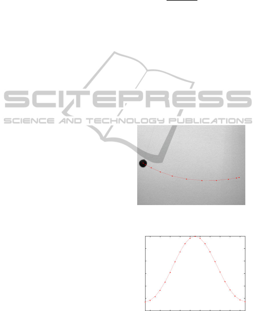
Figure 1: Camera image of a ball swing. Marked are
positions of various ball positions and its trajectory for the
first half of the harmonic period (Step1 and Step2).
Figure 2: Original HIC of the ball position for a full
harmonic period.
1
2
3
4
5
6
7
8
9
10
11
2 4 6 8 10 12 14 16 18 20
-300
-200
-100
0
100
200
300
Frames
Horizontal Image Coordinate Component
HARMONIC OSCILLATIONS MODELLING FOR THE PURPOSE OF CAMERA SYNCHRONIZATION
203
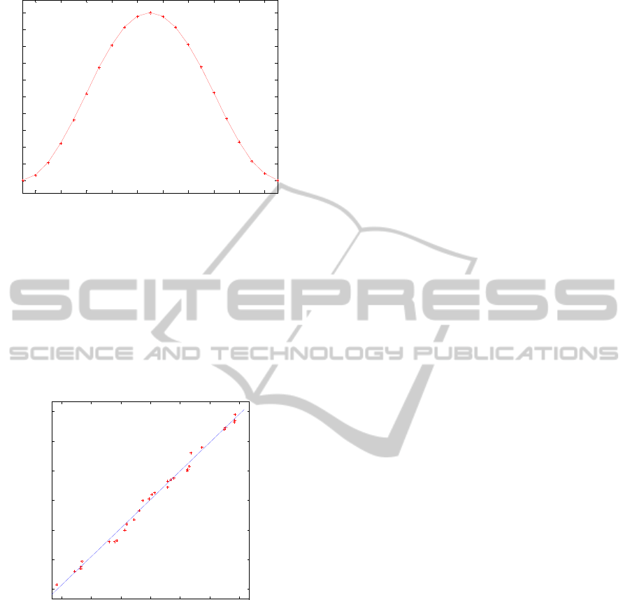
Figure 3: HIC of the ball position for a full harmonic
period after PCA processing and projective rectification
(Step3 and Step4).
Based on Figure 3, Step5 is carried out (Equation
(1)), where in this particular example A
1
and A
2
would be HIC values at frames 5 and 6 respectively.
Finally, computing similarly time offsets for other
camera(s) and taking the difference between those
times allow us to find subframe difference between
cameras (Step6).
Figure 4: Comparison of results between PGR method
(ground truth) and the proposed method. Linear
correlation coefficient is 0.996, while the mean absolute
difference between two methods measurements is 3.5ms.
4 DISCUSSION AND
CONCLUSIONS
Mathematical pendulum is a substantial idealization
of dimensionless point with mass m, attached to a
string (of negligible mass) and which can be swung
around its central equilibrium position. Ideally, 3D
ball movement is a planar movement where an
elongation of point can be described along one
coordinate axis. Furthermore, it can be shown that
an elongation of point swinging on its string can be
described according to sine law. Essentially, a
proposed method aims to model and recover this
sine like movement in one spatial dimension.
In practice camera(s) can be put in absolutely
arbitrary 3D position with respect to a pendulum.
Even if a plane of ball 3D movement is parallel with
a camera sensor it is very likely that camera is
rotated around its optical axis such that image
coordinate axis are not aligned with the spatial
coordinate axis of 2D coordinate system within a
ball oscillates. Therefore, the goal of PCA on the
raw detected ball center image coordinates (Step1
and Step2; Figure 1, Figure 2) is to try indentifying
the major direction of ball position change within an
image coordinate system. Re-computing ball center
image coordinates according to PCA direction axes
is a first step in aligning, as much as possible, the
image coordinates with the major spatial axes of
movements.
Second issue to consider is to model an effect of
a perspective distortion. Fortunately, the task is
somewhat simplified since we are primarily
interested with the change of spatial movement
(elongation) in one dimension only. It is well known
from a projective geometry that to compute
transformation H which relates one 1D projective
space to another 1D projective space we need at
least three correspondent point pairs. Extreme
positions of a ball in space where it is the furthest
from its equilibrium position can be expressed in
canonical projective coordinates as [-1 0]
T
and [1
0]
T
. Their correspondents on the image can be
approximated as the most extreme positions on the
image within a particular frame. Similarly an
equilibrium position can be described as [0 0]
T
where its image correspondent represent simply
position on the image of a ball standing still.
Consequently, when we apply PCA transformation
and homography H on the original image coordinate
values (Figure 2), we restore sine shape describing
our ball oscillation (Figure 3).
It is assumed that crossing point on time axis
(signal on (Figure 3)) is the common point in time
and space that both cameras can refer to for
synchronization (We recall that this point actually
represents an equilibrium ball position). In principle
we could pick another point for synchronization (e.g.
maximum/minimum of sine). However, this
particular choice, along with the reasonable
assumption that sine in this area is linear, enabled a
straightforward calculation of a subframe difference
(Step6) using Equation (1).
2 4 6 8 10 12 14 16 18 20
-1
-0.8
-0.6
-0.4
-0.2
0
0.2
0.4
0.6
0.8
1
Frames
Horizontal Image Coordinate Component
-60 -40 -20 0 20 40 60
-60
-40
-20
0
20
40
60
Proposed method - Subframe difference [ms]
PGR - Subframe difference [ms]
GRAPP 2012 - International Conference on Computer Graphics Theory and Applications
204

Shown results on Figure 4 reveals that the
proposed method yields basically the same data
about cameras time offsets as manufacturer does.
Compared to other methods, a proposed one is easily
applicable in outdoor and indoor conditions.
Pendulum itself is a cheap device that basically
anyone can make and use. It has such physical
structure that a large number of cameras can
simultaneously image and model a ball movement.
In turn, compared to many other methods, a
proposed one is easily applicable in outdoor and
indoor conditions. In fact, it allows cameras to be
perhaps conveniently arranged first for
synchronization and then calibrated, since it does not
require camera parameters for synchronization at all.
In addition, a proposed method SW implementation
is extremely simple, compared to some solutions
which use network as a tool, require PC server etc.
Our method comes down to tracking a ball on the
images for a couple dozen of frames (i.e. minimum a
period of ball swing) only.
The sine shape that our method recovers (Figure
3), potentially offers other means of processing
while trying to detect cameras subframe offsets. For
example, we plane to explore if interpolating a
sinusoid (from the directly detected ball positions),
and thereby finding a sinusoid corresponding phase
offset, would eventually give better results. Also, a
proposed modeling of harmonic oscillations is rather
generic where it is not necessary to use a pendulum
only. Therefore, other devices such as weight on a
spring or music metronome could be worth to
explore as well.
REFERENCES
Barros, R. M. L., Russomanno, T. G., Brenzikofer, R.,
Figueroa P. J. 2006. A method to synchronise video
cameras using the audio band. Journal of
Biomechanics 39 (4), 776–780.
Bradley, D., Atcheson, B., Ihrke, I., Heidrich, W. 2009.
Synchronization and Rolling Shutter Compensation
for Consumer Video Camera Arrays. IEEE
International Workshop on Projector-Camera Systems
(PROCAMS 2009).
Degueurce, C., Dietrich, G., Pourcelot, P., Denoix, J.,
Geiger, M., 1996. Three-dimensional kinematic
technique for evaluation of horse locomotion in
outdoor conditions. Medical and Biological
Engineering and Computation 34, 249-252.
Hartley, R., Zisserman, A. 2004. Multiple View Geometry
in Computer Vision. Cambridge Univ. Press.
Point Grey Research Inc. (2011). http://www.ptgrey.com/
Pourcelot, P., Audigie, F., Degueurce, C., Geiger, D.,
Denoix, J. M., 2000. A method to synchronise cameras
using the direct linear transformation technique.
Journal of Biomechanics 33 (12), 1751–1754.
Rai, P. K., Tiwari, K., Guha, P., Mukerjee, A. 2003. A
Cost-Effective Multiple Camera Vision System using
FireWire Cameras and Software Synchronization. 10th
IEEE International Conference on High Performance
Computing (HiPC) Hyderabad, India.
U. J., Suter, D. 2004. Using Synchronised FireWire
Cameras For Multiple Viewpoint Digital Video
Capture. Technical report MECSE-16-2004.
Department of Electrical and Computer Systems
Engineering, Monash University, Clayton, Austraila.
Yeadon, M. R., King, M. A., 1999. A method for
synchronizing digitised video data. Journal of
Biomechanics 32 (9), 983–986.
HARMONIC OSCILLATIONS MODELLING FOR THE PURPOSE OF CAMERA SYNCHRONIZATION
205
