
BIOMIMETIC COMPUTER-AIDED DESIGN AND
MANUFACTURE OF COMPLEX BIOLOGICAL SURFACES
Andrés Díaz Lantada, Pilar Lafont Morgado, Javier Echávarri Otero, Enrique Chacón Tanarro,
Eduardo de la Guerra Ochoa, Juan Manuel Munoz-Guijosa and José Luis Muñoz Sanz
Grupo de Investigación en Ingeniería de Máquinas – E.T.S.I. Industriales – Universidad Politécnica de Madrid,
C/ José Gutiérrez Abascal, nº 2. 28006, Madrid, Spain
Keywords: Biological Systems Modeling, Computer-aided Design, Biomimetics, Computational Geometry, Fractals,
Surface Topography.
Abstract: Conventional computer-aided design software does not yet provide special tools oriented to modeling the
complexity of biological systems, as such programs are mainly developed for promoting information
exchange in tasks related to industrial design and to parts with regular smooth surfaces. The process
explained in this study allows defining and precisely controlling the topography of surfaces from the design
stage, with help of computer-aided design tools. Its application to obtaining a biomimetic surface based on
the leaves of the Lotus flower (Nelumbo nucifera), renowned for its outstanding self-healing and
tribological properties, is shown as example. Some reflections on potential remarkable applications, linked
to the development of implants and prototypes with applications in several industries, have also been
included.
1 INTRODUCTION
Several studies have focused on the importance of
surface topography and microtexture for promoting
positive effects in all kinds of biomedical devices,
from implantable prosthesis to extra-cellular
matrixes and scaffolds for cell growth and tissue
engineering. These textures have a significant
influence in osseointegration of prosthesis, cell
proliferation and tissue growth given that those cells
and tissues seem to be more “comfortable” and
spread more quickly when faced with biodevices
with similar surface properties.
In addition the use of biomimetic surfaces can
help to introduce numerous desirable phenomena in
machine, mechanical and structural elements, thus
improving contact between parts, reducing wear or
even obtaining self-cleaning objects. However, the
process of introducing desired roughness on the
surfaces of man-made objects is still mainly linked
to carrying out machining operations, laser
processing or chemical attacks. In all these cases,
post-processing operations can be difficult to control
and it would be very positive to directly impose
special topographies from the design stage.
The use of fractal models for mimicking such
natural surfaces can prove to be useful for design
tasks. Fractals are rough or fragmented geometric
shapes that can be split into parts, each of which is
(at least approximately) a reduced-size copy of the
whole. The term fractal was coined by Benoît
Mandelbrot in the late 1970s / beginning of 1980s
and derives from the Latin fractus meaning “broken”
or “fractured” (Mandelbrot, 1982). The term is used
to describe complex geometries that are too intricate
to be formulated in conventional Euclidean terms,
with properties like self-similarity and defined
usually with simple recursive procedures.
Since the early works linked to fractal geometry,
it became clear that they could be used for
describing the geometries, patterns and roughness of
natural objects. Although fractals are commonly
considered to be infinitely complex (due to their
usual recursive definitions) “approximate fractals”
are easily found in nature, which usually display
self-similar structure over an extended, but finite,
scale.
By limiting the steps applied in a recursive
definition of a conventional fractal, approximate
fractals can be obtained, which mimic complex
natural geometries. Natural objects that are
approximated by fractals include clouds, mountains,
286
Díaz Lantada A., Lafont Morgado P., Echávarri Otero J., Chacón Tanarro E., de la Guerra Ochoa E., Munoz-Guijosa J. and Muñoz Sanz J..
BIOMIMETIC COMPUTER-AIDED DESIGN AND MANUFACTURE OF COMPLEX BIOLOGICAL SURFACES.
DOI: 10.5220/0003889002860290
In Proceedings of the International Conference on Biomedical Electronics and Devices (BIODEVICES-2012), pages 286-290
ISBN: 978-989-8425-91-1
Copyright
c
2012 SCITEPRESS (Science and Technology Publications, Lda.)

lightning bolts, coastlines, snowflakes, various
vegetables and several corporal and animal
geometries (Mandelbrot, 1982, Falconer, 2003).
During the last decade, increasing attention has
been paid to using fractals for promoting modeling,
design and simulation tasks in several areas of
Bioengineering. The most remarkable ones include
“modelling the behaviour of microorganisms”
(Tsyganov, 2007), “modelling complex organisms
and their systems (including human anatomy)” (Lin,
2004) and “modelling the surfaces of organs and
tissues” (Longoni, 2010).
In fact, very recent interest has appeared in the
use of fractals for mimicking the surfaces of organs
and tissues and thus improving the designs and in
vivo performance of several prosthetic devices,
although some limitations linked to the design
procedure still have to be overcome.
The process explained in this study allows
defining and controlling the texture and roughness of
surfaces from the design stage, with help of
computer-aided design tools. Its application to
obtaining a biomimetic surface based on the leaves
of the Lotus flower (Nelumbo nucifera), famous for
its remarkable tribological properties, is shown as
example (Barthlott, 1997).
The mentioned computer-aided design,
calculation and manufacturing technologies (CAD-
CAE-CAM), have become essential tools for
developing products. They allow 3D geometries and
alternative designs (to which calculations of stress,
deformations, ergonomics, dynamic response can be
applied) to be rapidly manufactured.
Moreover, these technologies can also be
employed to test materials and designs. They can
also prove to be extremely beneficial when applied
to the development of biomimetic devices with
advanced properties, even promoting personalization
of devices and special contact phenomena.
2 DESIGN PROCEDURE: FROM
MATHEMATICAL SURFACE
MODEL TO SOLID CAD FILE
2.1 Combining Euclidean
and Non-euclidean Geometry
We propose and explain in this section the use of
mathematical fractal models for designing the
complex and highly irregular surfaces of biomimetic
objects. In this way, parameters such as roughness,
waviness, skewness can be controlled from the
design stage and adapted in a more efficient way to
the requirements of final application.
Final multi-scale surface z(x,y) can be considered
as the sum of two different surfaces (z
m
(x,y) and z
n
(x,y)), each providing a relevant component at a
different scale level. In our case, the microscopic
bump-like behavior of the Lotus flower leaves can
be approximated by using a regular surface defined
by z
m
(x,y), for obtaining 10 μm size details. For
introducing an additional level of precision
(irregularities in the range of hundreds of
nanometers) z
n
(x,y) proves to give positive results if
based on fractal models.
In this study we have selected a fractional
Brownian fractal surface model for z
n
(x,y), which
has previously proved to be useful when carrying
out designs of natural surfaces (Falconer, 2003). The
following equations give the height “z” of the
surface, when assessing the function over a grid of
points given by their (x,y) coordinates.
The model uses several random functions (A
k
, B
k
,
C
k
), several control constants (λ, α, k) and an initial
height function “z
0
” can also be introduced.
According to the model, fractal dimension “D” of
the generated surface can be obtained from the
expression “D = 3 - α”, for having an indication on
how completely the fractal appears to fill space.
10/]))·sin()·cos([·sin(·),(
)10/)·sin(10/sin(·10),(
),(),(),(
1
0
∑
∞
=
−
++=
+=
+=
k
kkk
kk
kn
m
nm
AByBxCyxz
yxzyxz
yxzyxzyxz
λλ
ππ
α
2.2 Surface Generation
The calculations have been carried out with help of
Matlab software (Mathworks, version R2009) and
the data obtained have been stored in three-column
matrixes [X, Y, Z].
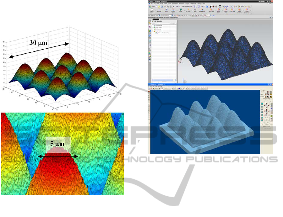
The command “surf” helps to represent the
surfaces linked to the mentioned matrixes. Figure 1
shows the result of evaluating function z(x,y) over a
grid of 300 x 300 points (corresponding to 30 μm x
30 μm). Consequently, distance between points of
the grid is similar to the scale of irregularities
(around 100 nm size) introduced by z
n
(x,y). Number
of iterations “k” has been limited to 10, enough for
introducing the fractal random-like irregularities,
and the following design values have been used:
λ = 1.5; α = 0.4; z
0
= 0.
Similarity with original topography of the Lotus
flower leaves is noteworthy, as can be seen if
compared with the photos from references
BIOMIMETIC COMPUTER-AIDED DESIGN AND MANUFACTURE OF COMPLEX BIOLOGICAL SURFACES
287
(Barthlott, 1997) or with the results from alternative
biomimetic manufacturing approaches (Groenendijk,
2007).
Figure 1: Mathematical surface mimicking the micro- and
nano-topography of the Lotus flower leaves.
2.3 Exporting Geometry to CAD
Software
Once the mathematical surfaces have been obtained,
the information stored in the form [X, Y, Z] can be
converted into .stl universal format, so that the
surface can be recognized and imported with a CAD
program, for additional design operations (i.e.
providing the surface with a thickness, copying the
surface atop a previously designed geometry…).
Different special software packages and “mesh to
solid” tools can be used for directly handling data in
.stl and enabling subsequent CAD operations. Figure
2 shows below the surface after importing the .stl
file with the help of NX-7.5 (Siemens AG) and the
solid body obtained after applying standard Boolean
design operations, for launching manufacture
through the 3D Lightyear
TM
software (3D Systems).
Figure 2: Handling the surface with CAD software for
obtaining a solid model.
2.4 Process Summary and Actuations
regarding Computer-aided
Engineering & Rapid
Manufacturing
Once obtained, CAD files enable the development of
several kinds of design validations (assembly,
relative movements…) and simulations (mechanical,
thermal, fluidic…) with the help of computer-aided
engineering resources, especially based on the use of
F.E.M. calculations.
Additionally the use of CAD tools can be very
beneficial when combined with a new set of
manufacturing techniques and technologies that have
appeared in the last two decades called “Rapid
prototyping and manufacturing technologies”.
These technologies help to address market
requirements in an ever more customized way, as
well as optimized in terms of time and cost, and
provide support for research work where physical
models (or prototypes) are needed for tests and
trials.
They are usually based on automatic “layer
manufacturing technologies” (like “laser
stereolithography”, “3D printers” or “selective laser
sintering”), rapid shape-copying processes, or
manufacturing processes through the elimination of
material (such as in computer-driven high speed
numerical control machining).
BIODEVICES 2012 - International Conference on Biomedical Electronics and Devices
288
The different technologies available allow
prototypes to be obtained rapidly in a wide range of
metallic, ceramic or polymeric materials with
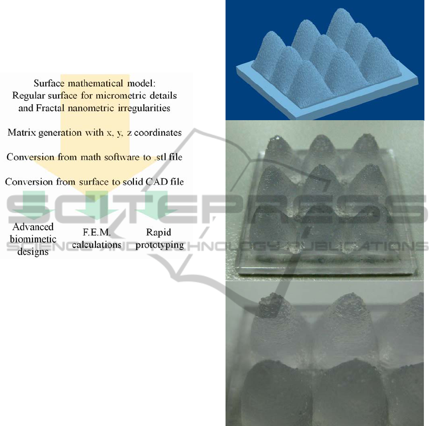
remarkable precision. The whole proposed design,
simulation and manufacturing process is
summarized in Figure 3.
Figure 3: Process scheme. OEPM P20103947 (Díaz
Lantada, 2010a).
Regarding the manufacture of fractal surfaces, our
previous research has helped to validate the use of
rapid prototyping for obtaining physical prototypes
with details in the range of 0.4 to 4 mm (Díaz
Lantada, 2010b).
The manufacture of more precise geometries, such
as the examples shown in this study, can be
accomplished by using some technologies such as
two-photon polymerization (Inführ, 2007), micro-
stereolithography (Choi, 2009), digital light
processing (Stampfl, 2007) and X-ray based
micromachining (Gad-el-Hak, 2002), for details
even down to hundreds of nanometers.
In any case Figure 4 provides an example of
prototype (30 x 30 mm
2
) manufacture through laser
stereolithography with a magnified scale due to
precision limitations. Further miniaturization can be
accomplished by using some of the aforementioned
technologies.
3 BRIEF DISCUSSION
OF POSSIBLE APPLICATIONS
The possibility of designing parts with surfaces
mimicking those from natural organisms can prove
to be of great value for incorporating advanced
Figure 4: Design and prototype manufactured using laser
stereolithography.
contact phenomena into devices for several
industries, thus promoting interactions with
surrounding elements (if the part is integrated within
a complex device) or tissues or organs (in the case of
an implant).
Among most promising applications we would
propose to focus in the near future on the design of
implants with optimized biocompatibility, devices
with self-cleaning properties, devices with ad-hoc
improved hydrophobicity or hydrophilicity,
scaffolds for cell and tissue growth and prototypes
for research linked to tribological phenomena,
including adhesion, lubrication, friction and wear.
BIOMIMETIC COMPUTER-AIDED DESIGN AND MANUFACTURE OF COMPLEX BIOLOGICAL SURFACES
289

In addition, combining novel advances in micro-
CT and medical imaging software (i.e. Mimics,
Materialise NV) for obtaining precise CAD data of
organs and biostructures (Shi, 2008, Guo, 2010),
with the possibility of incorporating even
nanometric features in a similar way to the presented
study, can be of great help for research linked to
enhanced modelling of biosystems.
4 CONCLUSIONS
A novel method for defining and controlling the
topography of surfaces from the design stage, even
mimicking the characteristics of biological systems,
has been presented. It is based on the combination of
regular surfaces for describing the micrometric
structure and additional fractal components for
providing the final nanometric details. As
application example a biomimetic design of the
surface of the Lotus flower leaves has been
explained.
Manufacture of such complex geometries can be
directly accomplished with help of additive rapid
prototyping technologies, what supposes a focus
change, from a more conventional “top-down”
(micro-machining, chemical etching, laser ablation),
to a more versatile “bottom-up” approach. The
flexibility of additive manufacturing also enables the
application of similar surface microtextures to the
complex geometries of prostheses and biodevices,
thus helping to introduce beneficial contact
properties for enhancing aspects such as wear
endurance or biocompatibility.
REFERENCES
Mandelbrot, B. B. (1982). The Fractal Geometry of
Nature, W. H. Freeman and Company.
Falconer, K. (2003). Fractal Geometry: Mathematical
Foundations and Applications. John Wiley & Sons.
Tsyganov, M. A., Kresteva, I. B., Aslanidi, G. V.,
Aslanidi, K. B., Deev, A. R. and Ivanitsky, G. R.
(2007). The mechanism of fractal-like structure
formation by bacterial populations. Journal of
Biological Physics, 25, 165-176.
Lin, D. W., Johnson S. and Hunt, C. A. (2004). Modeling
liver physiology: Combining fractals, imaging and
animation. Proceedings of the 26th Annual
International Conference of the IEEE EMBS, 3120-
3123.
Longoni, S. and Sartori, M. (2010). Fractal geometry of
nature (bone) may inspire medical devices shape.
Nature Proceedings.
Barthlott, W. and Neinhuis, C. (1997). Purity of the sacred
lotus, or escape from contamination in biological
surfaces. Planta, 202, 1-8.
Groenendijk, M. (2007). Self cleaning Lotus leaf imitated
in plastic by using a femtosecond laser. Univ. Twente,
Source: www.physorg.com
Díaz Lantada, A., Lafont Morgado, P. et al. (2010a).
Substrato cuasibidimensional para crecimiento de
células y tejidos y método de obtención del mismo.
Spanish Patent and Trademark Office, Patent
application number P201030957.
Díaz Lantada, A., Mosquera, A. A., Endrino, J. L. and
Lafont, P. (2010b). Design and rapid prototyping of
DLC coated surfaces for tissue engineering
applications. Journal of Physics, Conference Series,
252, 012003.
Infür, R., Pucher, N., Heller, C., Lichtenegger, H., Liska,
R., Schmidt, V., Kuna, L., Haase, A. and Stampfl, J.
(2007). Functional polymers by two-photon 3D
lithography. Applied Surface Science, 254, 836-840.
Choi, J., Wicker, R., Lee, S. H., Choi, K. H., Ha, C. S. and
Chung, I. (2009). Fabrication of 3D biocompatible /
biodegradable micro-scaffolds using dynamic mask
projection microstereolithography. Journal of
Materials Processing Technology, 209, 5494-5503.
Stampfl, J., Schuster, M., Baudis, S., Lichtenegger, H., Liska,
R., Turecek, C. and Varga, F. (2007). Biodegradable
stereolithography resins with defined mechanical
properties. Proceedings VRAP 2007, 283-288.
Gad-el-Hak, M. (2002). The MEMS Handbook, CRC
Press.
Shi, H., Farag, A. A., Fahmi, R. and Chen, D. (2008).
Validation of finite element models of liver tissue
using micro-CT. IEEE Transactions on Biomedical
Engineering, 55, 978-985.
Guo, X., Liu, X., Wang, X., Tian, F., Liu, F., Zhang, B.,
Hu, G., and Bai, J. (2010). A combined fluorescence
and microcomputed tomography system for small
animal imaging. IEEE Transactions on Biomedical
Engineering, 58, 2876-2883.
BIODEVICES 2012 - International Conference on Biomedical Electronics and Devices
290
