
SINGLE SNAPSHOT SYSTEM FOR THE FAST 3D MODELING
USING DYNAMIC TIME WARPING
Luis Ruiz, Xavier Mateo, Ciro Gr`acia and Xavier Binefa
Department of Information and Communication Technologies, Universitat Pompeu Fabra, Barcelona, Spain
Keywords:
3D Reconstruction, Mesh Zippering, Non-overlapping, Dynamic Time Warping.
Abstract:
In this work we explore the automatic 3D modeling of a person using images acquired from a range camera.
Using only one range camera and two mirrors, the objective is to obtain a full 3D model with one single
snapshot. The combination of the camera and the two mirrors give us three non-overlapping meshes, making
impossible to use common zippering algorithms based on overlapping meshes. Therefore, Dynamic Time
Warping algorithm is used to find the best matching between boundaries of the meshes. Experimental results
and error evaluations are given to show the robustness and efficiency of our method.
1 INTRODUCTION
Nowadays we can find on the market low cost range
cameras which allow the direct retrieval of depth in-
formation from a scene. This depth information can
be used in combination with the visual information
from another sensor in order to recreate the observed
scene in a 3D environment with high realism. The
increasing use of this kind of cameras has attracted
interest from different research fields like computer
vision, computer graphics, archeology, industrial pro-
totyping, etc.
The work presented in this paper describes the
development of a real-time 3D modeling system us-
ing only one range camera and with only one camera
snapshot. This system has been mainly designed for
human body reconstruction, although any other ob-
jects could also be applied. The resulting 3D model
can be used not only for 3D rendering, but also can be
stored as an avatar for the person and physical simu-
lations could be applied (for example, application of
clothing pieces).
Our system consists of two main phases: data ac-
quisition and mesh generation. In the data acquisition
phase the 3D information of the whole model is ac-
quired trying to minimize the needed space and the
time consumed. In the mesh generation phase we an-
alyze the method for creating a closed mesh based on
the choices in the data acquisition.
The structure of the presented system is as fol-
lows: in Section 2 a review of existing similar sys-
tems is presented. Section 3 shows some preliminary
aspects needed for the correct understanding of the
presented system, which is explained in Section 4.
Experimental results of the presented system are ex-
plained in Section 5, and finally conclusions and fu-
ture work are discussed in Section 6.
2 STATE OF THE ART
The 3D modeling of common objects is a long-time
studied field both in computer vision and in com-
puter graphics literature. Current technologies and
specially the new acquisition devices in the market
have allowed a high improvement on the result and in
the time requirements in order to obtain a full 3D rep-
resentation. Nowadays, we can find complete systems
that try to do this work almost automatically.
One of the most well-known systems is the one
present in the internet service Photosynth, which cor-
responds to the study presented in (Snavely et al.,
2006). The main advance in this study was the pos-
sibility of detecting and matching 2D keypoints from
very different images (regardless of the viewpoint or
the camera used), registering them and therefore mak-
ing possible their placement in a 3D environment.
Also in the field of 3D modeling from 2D im-
ages it must be taken into account the work presented
in (Pan et al., 2009). With a simple video camera
and a rotating object in front of it, the presented sys-
tem tracks different keypoints of the image along the
sequence, applying afterwards a bundle adjustment
317
Ruiz L., Mateo X., Gràcia C. and Binefa X..
SINGLE SNAPSHOT SYSTEM FOR THE FAST 3D MODELING USING DYNAMIC TIME WARPING.
DOI: 10.5220/0003867003170326
In Proceedings of the International Conference on Computer Vision Theory and Applications (VISAPP-2012), pages 317-326
ISBN: 978-989-8565-04-4
Copyright
c
2012 SCITEPRESS (Science and Technology Publications, Lda.)
(Hartley and Zisserman, 2004) which iteratively re-
fines the 3D placement of this keypoints. In a second
phase, the paper uses a variant of Delaunay triangula-
tion to obtain the final mesh of the object.
Despite these already explained works, current ap-
proaches mainly make use of the so-called range cam-
eras, which provide a depth image in addition to the
usual visible image. One of the first integral systems
using this kind of cameras was the work presented in
(Rusinkiewicz et al., 2002), including the acquisition,
registration, surface triangulation and final rendering.
Its main drawback was the need of user manipulation
in some aspects of the process, producing in addition
a higher time consumption.
A more recent approach using range cameras is
presented in (Weise et al., 2011). This paper also con-
tains the whole process of the 3D modeling, from the
acquisition to the final rendering, and solves most of
the problems present in (Rusinkiewicz et al., 2002),
in part thanks to the computer processing advance be-
tween both papers.
It must be taken into account that all the literature
available nowadays requires the rotation of the object
around its own axis, or equivalently, the rotation of the
camera. These both possibilities are not suitable for
our application, since the rotation of a person could
produce small movements in his body and the rotation
of a camera around the person requires a huge need of
space.
3 PRELIMINARY WORK
3.1 Camera Used: Microsoft Kinect
The range camera used during experiments is the Mi-
crosoft Kinect, recently released. The Kinect device
has a RGB camera, an IR camera and one laser-based
IR projector. In order to obtain the range image, this
camera does not use the method of Time Of Flight
(Gokturk et al., 2004), but triangulation between cap-
tured image and a known pattern missed by sensor.
While the laser-based IR projector emits a mesh of IR
light to the scene, the IR camera captures the distance
of every point of the IR mesh emitted by the projector.
For a typical Kinect, the resulting RGB image has
a resolution of 640 x 480 pixels, and the depth im-
age has a resolution of 320 x 240 pixels. The IR and
RGB cameras are separated by a small baseline so
they must be calibrated between themselves. How-
ever, since this is a common used range camera, the
values of the calibration are well known by the com-
munity.
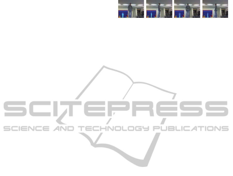
Images obtained with the Microsoft Kinect are
Figure 1: Sequence of the scanning process using a turning
table example. Only 4 scans are shown, but the sequence
can be composed by a large number of scans. For each scan,
the RGB image and the depth image is shown.
noisy and static objects tend to be detected with dif-
ferent range in consecutive captures. In addition, the
device has problems in detecting object contours and
usually small structures could not be detected. For
these reasons the depth image should usually be fil-
tered in order to avoid these inconveniences.
The resulting 3D image after using the Kinect is
a set of 3D points, without any surface information.
However, thanks to the known IR pattern emitted by
the sensor it is simple to directly connect the neighbor
3D points and make a fast triangulation.
3.2 Problems with Existing Approaches
In the literature exist different ways to solve the pro-
posed problem of 3D modeling. In this work we study
only the two more relevant ones: the turntable ap-
proach and the multiple cameras approach.
3.2.1 Turntable Approach
The most common method used in 3D modeling con-
sists on placing the object on a turning table, allowing
the capture of the object from several viewpoints. The
3D sensor can be fixed in an appropriate place and
successive 3D captures of the object are obtained dur-
ing its rotation. The result of this scanning process is
a set of partial scans of the object, including both the
depth and the RGB information. An example using a
model person is shown in Figure 1.
Once the different partial scans have been ob-
tained, the multiple views are registered together in
order to obtain a full-side representation. For this pur-
pose usually a 2-step method is used, starting with
the so-called pairwise registration between pairs of
partial scans (Besl and McKay, 1992), followed by
the multiview registration, which makes use of the lo-
cal information of multiple pairwise registrations and
minimizes the global registration error (Sharp et al.,
2004), (Shih et al., 2008).
However, this kind of acquisition method is not
suitable for human modeling. Minimal movements of
the subject during his rotation can produce errors in
the final registration. Also, many people are reluctant
to be rotated and this can be a problem for a possible
commercial product.
VISAPP 2012 - International Conference on Computer Vision Theory and Applications
318
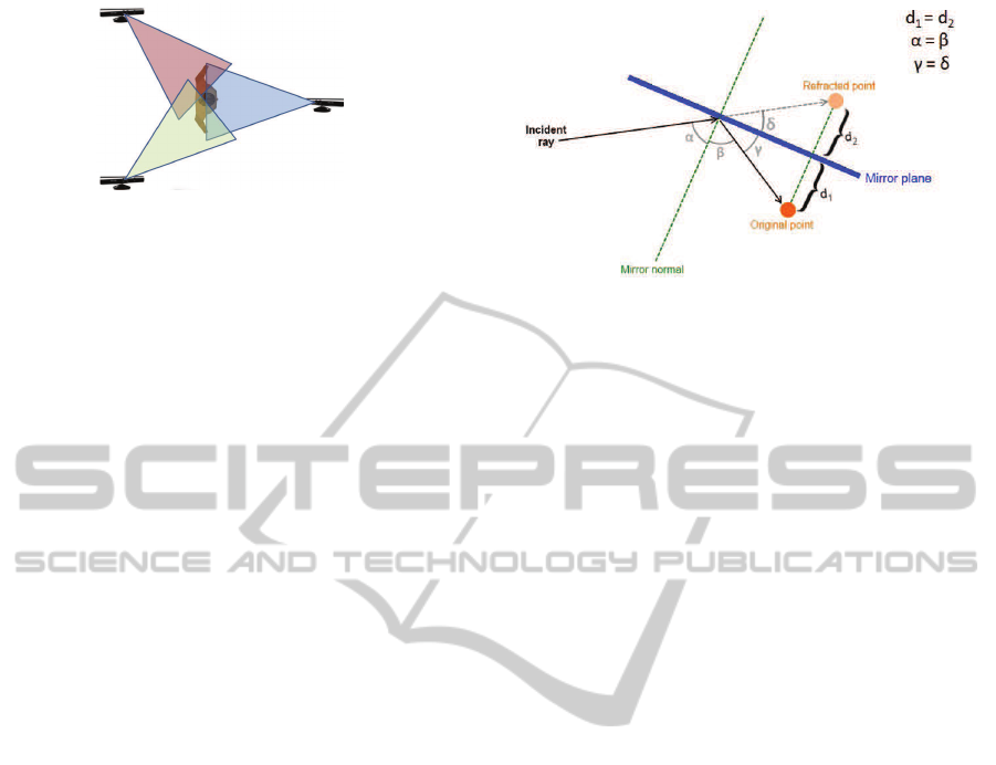
Figure 2: Three viewpoints surrounding the person at each
120 degrees.
3.2.2 Multiple Range Cameras Approach
Another possible solution for the human modeling
would be the use of multiple range cameras surround-
ing the person like is shown in Figure 2. Although in
the figure only three cameras are shown, this number
could be increased. The main advantage of this ap-
proach is that the person should not be moved, avoid-
ing then their possible movements.
The main problem of having three Kinects run-
ning at the same time is that, as explained in section
3.1, the range camera projects an IR pattern over the
scene and later compares the deformation of this pat-
tern against it stored pattern. If there are more than
one range camera projecting different IR patterns at
the same time, interferences between them can exist.
A possible solution would be to take snapshots of the
scene for every range camera but at different times so
the IR patterns should not interfere.
However, although this has a simple implementa-
tion it requires a lot of space on the scene. In order to
capture the whole height of a medium height person
every range camera must be at around 3 meters away
from the object and these 3 meters of radius should
not contain any occluding object.
4 PROPOSED APPROACH
The system proposed in this paper is mainly com-
posed of two different phases: the model acquisition
phase where the 3D points of the person are cap-
tured, and the mesh triangulation and zippering phase,
where the mesh is created from the set of 3D points.
4.1 First Phase: Model Acquisition
First phase for the presented system consists in the
acquisition of the 3D points from the person. We pro-
pose a novel method using only one range camera and
two mirrors, making possible to acquire all the nec-
essary information with one single snapshot, and re-
ducing also the space requirements of the previously
explained approaches.
Figure 3: Reflection of a single point on the mirror. The
original point is placed in front of the mirror, and the inci-
dent ray indicating the view of the camera aims to the mir-
ror and can see the original point thanks to the reflection.
However, the depth camera only detects a distance to the
point, and this distance is placed in straight line according
to the direction of the incident ray. According to the ideal
reflection rules, the angle α between the incident ray and
the normal plane is equal to the angle β produced between
the reflected ray and the normal plane. In the same way, the
angle γ is equivalent to the angle δ, and therefore d
1
and d
2
have the same distance.
4.1.1 Mirrors Behavior with the Range Cameras
In order to solve the proposed problem we present a
novel approach that makes use of two standard mir-
rors which reflect both IR and visible light.
A standard mirror reflects the visible light, but it
also reflects the IR light. If we place a Microsoft
Kinect in front of a mirror, the IR pattern emitted by
the camera reflects in the mirror and therefore the sen-
sor is able to capture the 3D structure of the objects
present in the reflection. This method has however
a little disadvantage which can be easily solved: the
range camera does not recognize that this is a reflected
pattern, so it will place the reflected 3D structure in
straight line, i.e., at the other side of the mirror.
A simple explanationfor a single point is shown in
Figure 3. As it can be seen in the figure, the Microsoft
Kinect will place the distance to the point in straight
line and therefore the refracted point will be placed
at the other side of the mirror. According to the ideal
reflection rules, this new refracted point will be placed
in perfect symmetry regarding the original point with
respect to the mirror plane.
Applying this theoretical idea to our study case,
we can see the frontal view and the two reflected
views of a person in Figure 4. As expected, the re-
flected 3D structures are placed accordingly at the
other side of the mirror.
The main advantage of this technique is that it re-
duces the total need of space. As the field of view of
the Kinect camera is enough for capturing the whole
mirror, the IR pattern is already extended in the reflec-
SINGLE SNAPSHOT SYSTEM FOR THE FAST 3D MODELING USING DYNAMIC TIME WARPING
319
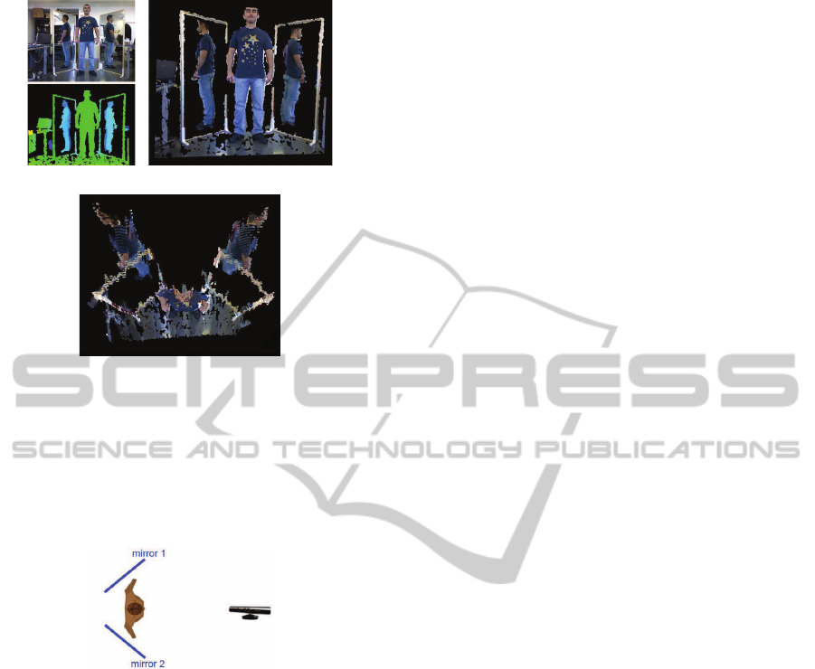
(a) (b)
(c)
Figure 4: In (a), the RGB image and the depth image ob-
tained from Kinect are shown (objects with a depth higher
than a threshold have been filtered out for a better under-
standing). Fusing the information of both images we can
represent the 3D model of the scene, shown in (b) and (c).
Although it can not be seen in (b), in (c) is clearly seen that
the reflected parts of the person are placed at the other side
of the mirrors.
Figure 5: Example of the acquisition process setup. Using
the reflection of the mirrors, the rest of the body can be
inferred.
tion plane and therefore we do not need the additional
space behind the person. An schema of the final dis-
position of the elements is shown in Figure 5, where
the total space needed is significantly lower than in
Figure 2 and more appropriate for small spaces (for
example a dressing room).
However, using this technique an important dis-
advantage arises. Due to the extra distance that the
IR pattern has to travel when it reflects in the mirror,
the 3D resolution of this pattern will be slightly lower
when it illuminates the posterior part of the person. In
consequence the posterior views of the 3D modeled
person will have a lower resolution in comparison to
the frontal view, giving us a model which is not uni-
form in all its surface.
Another disadvantage that must be taken into ac-
count is that using this mirrors technique, we will al-
ways obtain three point sets without overlapping re-
gions between them. If a point of the scanned surface
is illuminated by the direct IR pattern and a reflected
IR pattern, both patterns will interfere themselves and
therefore the range camera will not be able to decide
which is the correct range. In fact, this is the same
effect as if an object is illuminated by two range cam-
eras at the same time or when a camera aims directly
at another range camera.
4.1.2 Mirror’s Plane Detection and Registration
In order to deal with the mirrors, we first need to de-
tect where they are. For this purpose, the first step that
we have to do is to detect some points on the mirror
frame, which will be denoted by P = {p
i
}. This point
detection can be achievedby a manual selection of the
points or using an automatic process for detecting the
lines corresponding to the frames.
The selected points of the mirror P = {p
i
} are
used in order to obtain the basis matrix M
mw
which
converts points from the mirror reference frame to the
world reference frame. M
mw
is computed from the
three eigenvectors (~a,
~
b,~c) obtained after applying the
Singular Value Decomposition of the covariance ma-
trix of P:
M
wm
=
a
x
b
x
c
x
a
y
b
y
c
y
a
z
b
z
c
z
(1)
Note that the first two eigenvectors with higher
eigenvalues (~a,
~
b) estimate the plane subspace of the
points P = {p
i
} and the third eigenvector (~c) is the
estimation of the plane’s normal direction.
As stated before, we need to invert the reflection
produced by the mirror. Since this is a reflection, we
only need to apply a flip on the z axis for each point
with respect to the plane described by the mirror’ssur-
face. If we have a point p
w
in world coordinates, to
express it into mirror coordinates we apply
p
m
= M
−1
mw
(p
w
− c
m
) (2)
, where c
m
corresponds to the centroid of all the frame
points P = {p
i
} which belong to this mirror.
Now that the point is in mirror coordinates, for
flipping the z axis we apply:
p
′
m
= (p
m
x
, p
m
y
,−p
m
z
) (3)
Once we have flipped the z axis, the new point
p
′
w
is positioned on the mirror but in mirror coordi-
nates. To transform from mirror to world coordinates
we use:
p
′
w
= (M
mw
p
′
m
) + c
m
(4)
VISAPP 2012 - International Conference on Computer Vision Theory and Applications
320
4.2 Second Phase: Mesh Triangulation
and Zippering
After the model acquisition phase a set of registered
3D points is obtained. In order to obtain a real 3D
model of the person a closed mesh is needed, so in this
second phase this requirement is achieved using two
complementary techniques: mesh-based triangulation
and zippering.
4.2.1 Mesh-based Triangulation
The reconstruction of meshes from a set of 3D points
is a long-time studied subject in the computer graph-
ics literature. Although existing methods produce
good results, they usually require a set of 3D points
with low noise and, if possible, with a uniform reso-
lution along the object. Images obtained with the Mi-
crosoft Kinect camera are noisy and in addition the
use of mirrors produces an irregular resolution due to
the extra distance caused by the reflection, so the tri-
angulation of the set of 3D points obtained from the
acquisition phase usually gives a non-satisfactory re-
sult.
However, the use of Kinect camera has an im-
portant advantage for our purposes. As previously
stated in Section 3 the image obtained can be fast tri-
angulated thanks to the ordered 3D points obtained
by the IR pattern. In one single image of the sensor
we can obtain three different meshes at a time (the
frontal mesh and the two posterior meshes which will
be obtained from the mirrors), so the triangulation
must be done before the mirror projection happens
because although after projection the position of the
vertices change, the local connectivity between each
other does not. In Figure 6 we can see two of the
meshes that we must join, which havebeen previously
fast triangulated.
4.2.2 Zippering with Dynamic Time Warping
Once the triangulation is done, it is necessary a pro-
cess for connecting the 3 meshes generated: frontal,
back-left and back-right. In the literature we can find
some works related to stitching meshes: (Turk and
Levoy, 1994), (Soucy and Laurendeau, 1995), (Sappa
and Garcia, 2000). Although these methods produce
good results, all of them are focused on overlapping
meshes. However, as previously explained in Section
3, in our system the three meshes cannot overlap. In
addition, it must be taken into account that a major
problem for this zippering is the presence of meshes
with different resolution, due to the fact that both back
meshes are obtained with a higher traveled distance
of the IR pattern. In order to solve these problems a
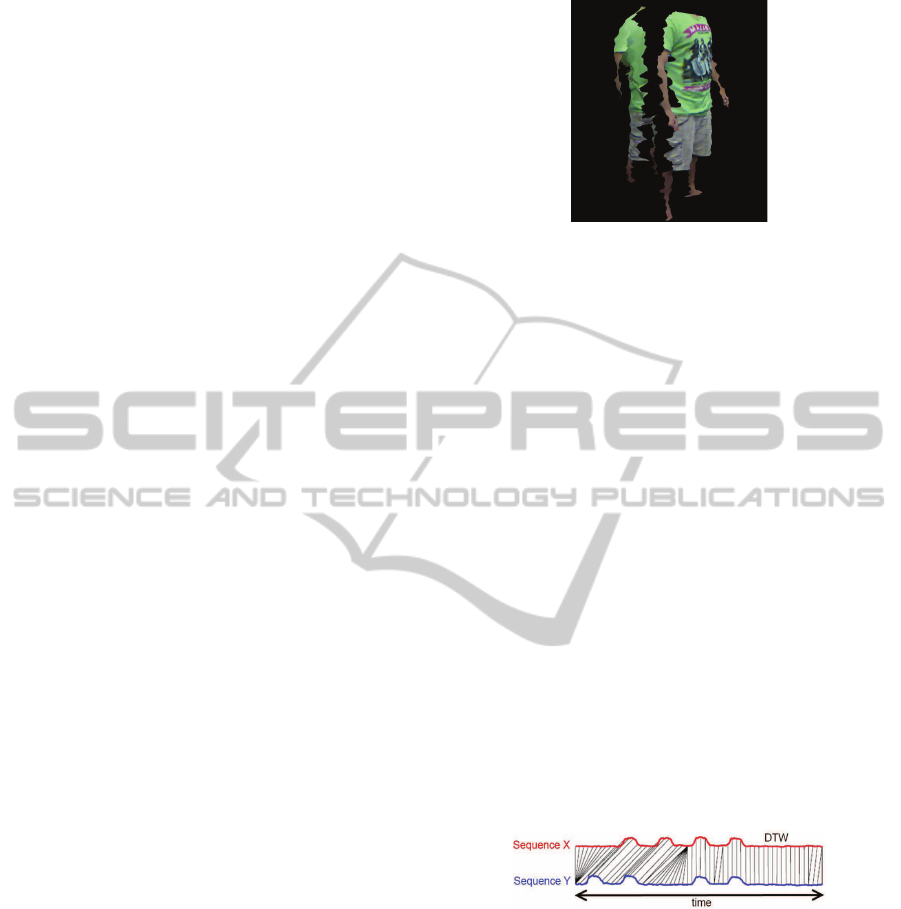
Figure 6: Frontal mesh and back-right mesh. Views are
intentionally separated in Z axis for better comprehension.
novel approach for mesh zippering based on Dynamic
Time Warping is proposed.
Dynamic Time Warping (called DTW in the fol-
lowing) (Sakoe and Chiba, 1978) (M¨uller, 2007) is
an algorithm to find the optimal alignment between
two sequences. It was designed to compare different
speech patterns in automatic speech recognition, but
is also usual in fields like handwriting or signature
recognition.
The objective of DTW is to compare two se-
quences X := (x
1
,x
2
,...,x
N
) and Y := (y
1
,y
2
,...,y
M
) of
length N and M respectively (see Figure 7). The se-
quences must be ordered, but they do not need to have
the same number of features. To compare two dif-
ferent features x ∈ X and y ∈ Y a local cost measure
c(x,y) needs to be defined. The definition of this lo-
cal cost measure must be established according to the
particularities of the studied case. Evaluating the lo-
cal cost measure for each pair of elements of the se-
quences X and Y, the cost matrix C ∈ R
NxM
is ob-
tained. Having this cost matrix, the optimal alignment
between X and Y can be found by looking for the path
along C with minimal cost.
Figure 7: Time alignment of two time-dependent se-
quences. Intuitively, the sequences are warped in a non-
linear fashion to match each other. Aligned points are indi-
cated by the transversal lines.
Since mirrors are oriented vertically, the way that
the meshes must be joined is through the coronal
plane of the person, that is, the vertical plane which
divides the human body into front and back. During
the process of stitching we have to decide which side
of every mesh matches the side of the other mesh.
Thus, we need to find the points where coronal and
sagittal plane intersect for every mesh.
For every possible match, DTW retrieves a warp-
ing matrix and an accumulated distance that brings us
SINGLE SNAPSHOT SYSTEM FOR THE FAST 3D MODELING USING DYNAMIC TIME WARPING
321
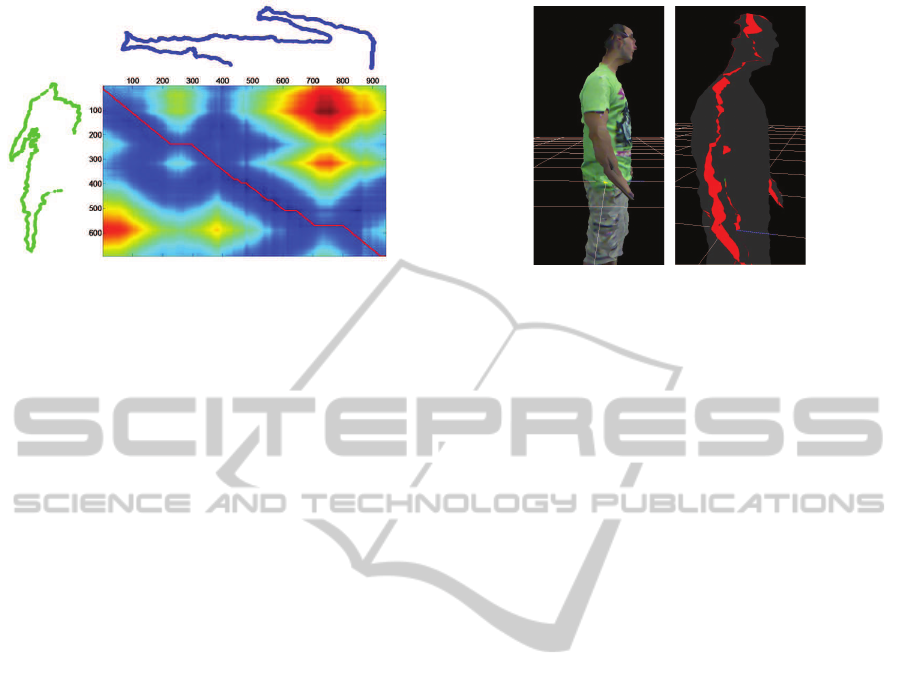
Figure 8: Cost matrix between the contour of the frontal
view (blue color) and the contour of one posterior view
(green color). As can be seen, the contour of the poste-
rior view has a lower number of points because of the extra
distance traveled by the IR pattern. In the cost matrix rep-
resentation, the red line indicates the optimal path which
produces a minimum overall cost.
the value of similarity between boundaries. In Fig-
ure 8 a distance matrix is shown, where the horizontal
axis corresponds to the first sequence and the vertical
axis corresponds to the second one.
Once we know which parts must be stitched we
need to generate the connectivity information, creat-
ing then the faces. During the computation of DTW,
a warping matrix is generated. This warping matrix
stores the correspondences between each point of the
sequence. The warping matrix will always return the
correspondences that better match in these sequences.
In our case, we can use this information for tri-
angulating the two meshes, and the triangulation will
be straightforward. In Figure 9 we can see the model
correctly zippered by our implementation.
5 EXPERIMENTAL RESULTS
A new system for 3D modeling is proposed in this
paper. In order to evaluate the accuracy of the system
three different experiments are proposed, focusing on
the two major contributions present in this paper: the
presence of mirrors for a single snapshot 3D modeling
and the use of Dynamic Time Warping for zippering
meshes without overlap.
5.1 Loss of Information Due to the
Mirrors Reflection
Using a mirror to reflect the object helps us to reduce
the global space needed in the scene. However, a loss
of information is produced by this reflection, and this
loss of information affects to the final reconstruction.
This loss can be produced either by the quality of the
Figure 9: Model stitching using DTW. In the right image is
shown, in red color, the zippered faces between the meshes.
reflection caused by the mirror or by the extra dis-
tance done by the IR projection which produces a loss
of quality in the generated mesh. In order to evaluate
only the loss produced by the reflection the following
experiment is proposed. First, the person is placed
in front of a mirror, and the 3D data produced by
the reflection is stored, annotating also the distance
of the camera with respect to the mirror an the dis-
tance between the mirror and the posterior part of the
person. In a second part of the experiment, without
moving the object and discarding the mirror, the cam-
era is placed behind the object (in the direction of the
reflection) at the same distance than the sum of the
two distances stored before. A schema of this process
can be seen in Figure 10, where the only difference
between two captures is the reflection of the mirror,
because the total distance will be equivalent. Having
these two 3D images available, we can now compare
both in order to see if it exists a loss in range accuracy
or in the resolution.
In order to avoid the possible movements of a per-
son between the captures in the experiment a man-
nequin will be used. In addition, to avoid the noisy
3D images produced by the Microsoft Kinect a total
amount of 10 range frames is captured in both setups
and the mean value for each 3D point is assigned.
In Figure 11 the results of this experiment are
shown. In order to compare both meshes the Haus-
dorff distance (Cignoni et al., 1998) between the
meshes is used, sampling one of the meshes and com-
puting for each sample the Hausdorff distance to the
closest point on the other mesh. Visually comparing
the 3D meshes obtained from the experiment (subfig-
ures 11(b) and 11(d)), it can be seen a change of the
texture color in the shirt (produced by the light re-
flections in the mirror) and a loss of 3D points in the
edges of the reflected mesh. A clear example can be
seen in the hand, which is less defined in the reflected
3D view in subfigure 11(b). This loss of resolution in
the edges is confirmed after computing the Hausdorff
VISAPP 2012 - International Conference on Computer Vision Theory and Applications
322
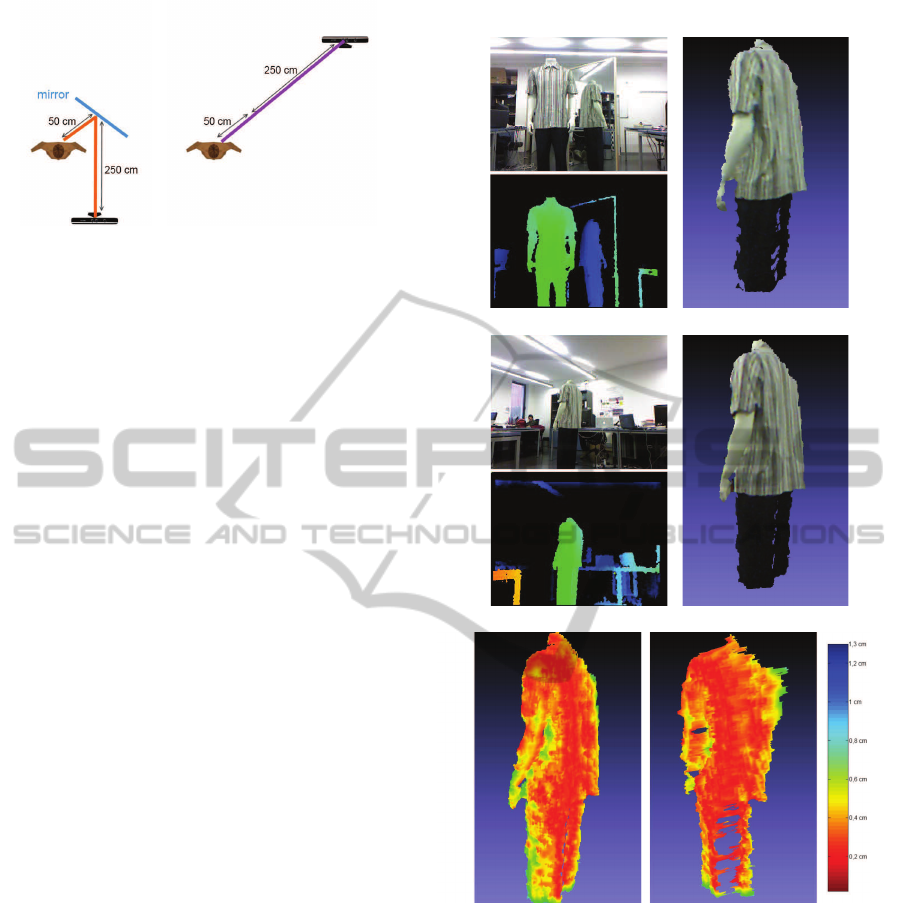
(a) (b)
Figure 10: For each studied object, first the 3D of the poste-
rior part is extracted as can be seen in (a). The resulting 3D
is obtained at a distance which is equivalent to the distance
of the camera to the mirror plus the distance of the mirror to
the object. In a second phase, in (b), the mirror is discarded
and the camera is placed at the same distance but in straight
line, so the total distance will be equivalent.
distance, which is close to zero in the inner part of the
meshes and tends to be higher in the edges. The max-
imum distance between both meshes is 1,2897 cm.
and the mean distance for all the samples is 0,2083
cm.
In addition to the Hausdorff distance between
meshes, the loss of resolution due to the mirror re-
flection is analyzed. The 3D mesh obtained with re-
flection (subfigure 11(b)) has a total of 18097 vertices
and 34985 faces. On the other side, the mesh obtained
with direct capture (subfigure 11(d)) has 22755 ver-
tices and 44303 faces, so the percentage of loss using
a mirror is about 20%, both for vertices and faces.
5.2 Loss of Information Due to the
Extra Distance in the Mirrors
The following experiment was based on taking snap-
shots of the mannequin at different distances in order
to evaluate their possible implication in the quality of
the generated mesh. Different captures at 300, 350,
400, 450 and 500 cm. are obtained, and the results can
be seen in Figure 12. Results show that the distance
with respect to the mannequin affects to the quality
of the generated mesh, where for higher distances the
quality of the mesh is greatly reduced.
In Figure 13 the mean value of the Hausdorff
distances for each separation of the mannequin are
shown, starting from 300 cm. (which has a distance
of 0 cm. because is compared to itself) to the 500 cm.
We can observe an exponential behavior, where for
each additional 50 cm. the Hausdorff distance is near
to be doubled.
In addition to the inaccuracy produced by the dis-
tance, also the loss of vertices and faces is evaluated.
In Figure 14, a plot indicating the number of vertices
and faces for each capture is shown. We can see that
(a) (b)
(c) (d)
(e)
Figure 11: (a) Visible image and depth image using the mir-
ror. With this information, and after computing the flip of
the mirror, the obtained 3D representation is shown in (b).
Discarding the mirror and placing the Kinect at the back
side of the mannequin with the same distance, the resulting
images and the 3D representation are shown in (c) and (d).
In (e) we can see the result after comparing both 3D meshes
using the Hausdorff distance, using the same point of view
used previously and another view looking at the back.
the results fits with an exponential decay model.
5.3 Evaluation of the Zippering Process
In this section we discuss results obtained with the
stitching process using Dynamic Time Warping. The
SINGLE SNAPSHOT SYSTEM FOR THE FAST 3D MODELING USING DYNAMIC TIME WARPING
323
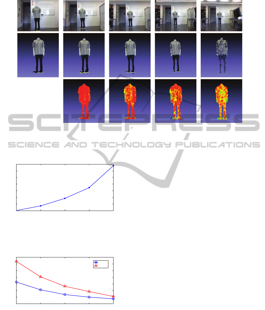
(a) (b) (c) (d) (e)
Figure 12: At the top, captured visible image of the mannequin at 300, 350, 400, 450 and 500 cm. respectively. In the middle
row the resultant 3D meshes are shown, having a degradation of the mesh for the higher distances. At the bottom, Hausdorff
distance of the 3D meshes against the first mesh, which is considered as reference. We can see that due to the range camera
resolution, the farther is the object, the bigger the difference.
300 cm. 350 cm. 400 cm. 450 cm. 500 cm.
0,5 cm.
1 cm.
1,5 cm.
2 cm.
2,5 cm.
3 cm.
3,5 cm.
Distance to the object
Hausdorff distance with respect to
the reference mesh
Figure 13: Mean value of the Hausdorff distance for a sep-
aration of 300 cm.(Hausdorff 0 cm.), 350 cm. (Hausdorff
0.3517 cm.), 400 cm. (Hausdorff 0.9170 cm.), 450 cm.
(Hausdorff 1.7277 cm.) and 500 cm. (Hausdorff 3.3804
cm.).
300 cm. 350 cm. 400 cm. 450 cm. 500 cm.
10.000
20.000
30.000
40.000
50.000
60.000
70.000
Distance to the object
Complexity of the obtained 3D mesh
vertices
faces
Figure 14: Relation between complexity of the mesh and
distance to the object.
objective is to evaluate the loss of information which
is produced in the 3D model due to the zippering be-
tween the 3 meshes.
Since the noise produced by the range camera
used causes random mesh generation, a reliable ex-
periment with a captured 3D model or person can-
not be done. For this, a synthetic human model is
used, splitting it in 3 parts and later zippering using
our method. The synthetic model is splitted in two
parts by the coronal plane, and afterwards the back
part is splitted again by its sagittal plane, giving us
the 3 parts obtained as we would use the mirrors.
The split of the parts is done by subtracting points
of the synthetic mesh. Since the triangulation of the
mesh depends on these 3D points, the faces composed
by the subtracted points will disappear, giving us an
irregular split which is similar to the split produced
by the mirrors.
Using the mirrors approach proposed in this paper,
in addition to the split of the model, a loss of resolu-
tion on the back of the model is produced. To emulate
this loss on the synthetic model a simplification on
the two back meshes between 0% and 50% is done.
To evaluate the zippering result, Hausdorff distance
between the result of the zippering and the original
synthetic mesh is computed.
In Figure 15 the result of zippering the splitted
model with a loss of 40% for the posterior meshes can
be seen. As expected, Hausdorff distance increases in
the zones where there are more difference in the reso-
lution.
In order to evaluate the accuracy of the zippering
process with respect to the resolution degradation on
the back meshes, the mean value of the Hausdorff dis-
tance is analyzed for degradation of 10%, 20%, 30%,
VISAPP 2012 - International Conference on Computer Vision Theory and Applications
324
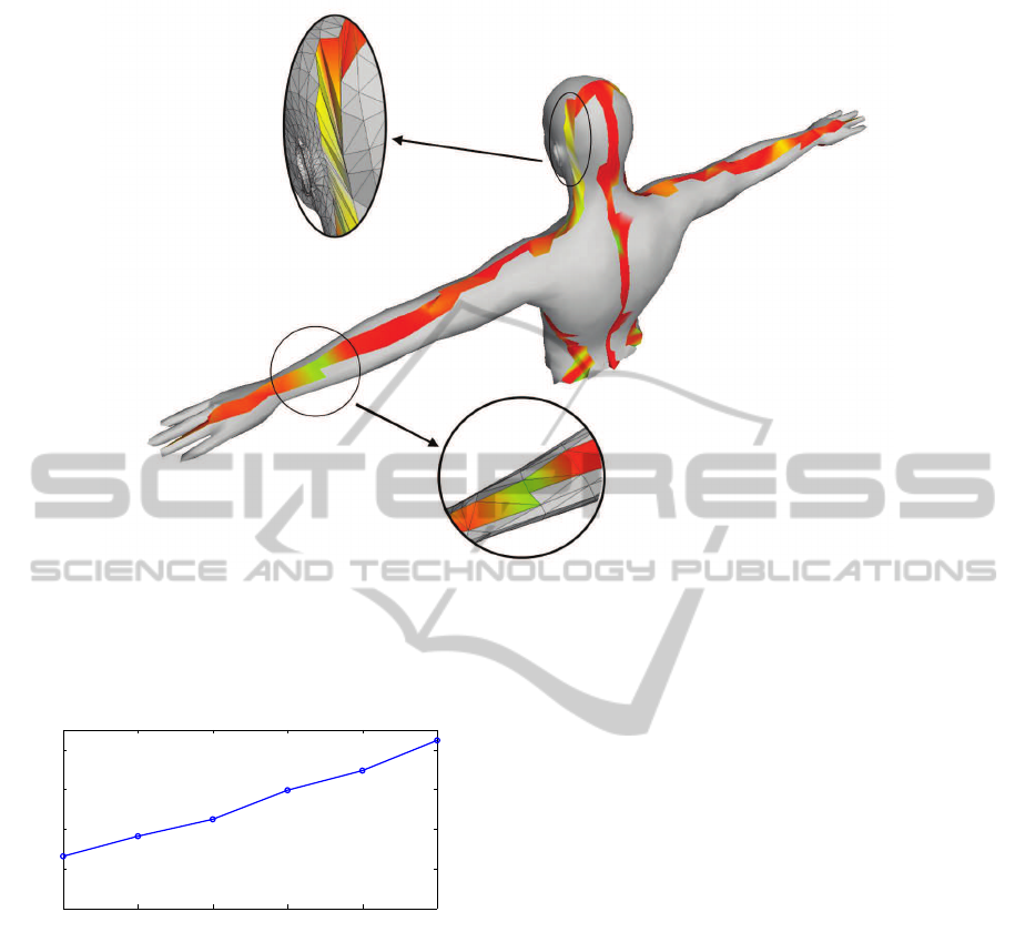
Figure 15: Result of the zippering for a reduction of 40% for the two back meshes. Red color indicates a low Hausdorff
distance, while blue color indicates a high Hausdorff distance. In the image magnification of the head it can be seen that the
high Hausdorff distance is produced by the high difference between the resolutions of the frontal and the back mesh. In the
image magnification of the arm, a discontinuity of the mesh produce a high Hausdorff distance because the original mesh had
two triangles in this position, while our zippering process only triangulates with one triangle.
0 10 20 30 40 50
0.1 cm
0.2 cm
0.3 cm
0.4 cm
Percentage of degradation for the back meshes
Mean value of the Hausdorff distance
Figure 16: Evolution of the mean Hausdorff distance for
different degradation percentage of the back meshes.
40% and 50%. The results are displayed in Figure
16, where the evolution of the accuracy has a linear
behavior.
6 CONCLUSIONS AND FUTURE
WORK
In this work we have presented a novel system for the
efficient modeling of a human body using only one
range camera and two mirrors. Our method presents
good characteristics in terms of efficiency, compact-
ness and low memory usage.
The experiments show that, with a low-cost range
camera like the Microsoft Kinect and two mirrors, a
fast 3D reconstruction can be done. The use of mir-
rors allows a reduction of the space needed for the
modeling, but on the other side produce a degrada-
tion on the created 3D model. This degradation is
produced by two factors: the reflection itself, which
produces a loss of about 20% in the number of ver-
tices and faces, and the additional distance of the IR
pattern after bouncing at the mirror.
Due to the use of the mirrors there was no overlap
between the meshes and therefore the traditional tech-
niques for stitching could not be implemented. Dy-
namic Time Warping has demonstrated that is a pow-
erful algorithm not only suitable for speech recogni-
tion, but also for many other fields.
In relation with future work, many challenges are
open and some issues should be solved. One of
these issues is the necessity to avoid the non-manifold
meshes, which could produce errors in the hole filling
algorithms. If a closed volume is achieved, accom-
plishing manifoldness, the next step could be to sub-
mit this mesh to an automatic rigging process (Baran
and Popovi´c, 2007). After this, we would have a 3D
model with a skeleton inside with every face of the
model correctly weighted respect to each bone. Us-
ing this rigged model and the skeleton-tracking capa-
bilities of Microsoft Kinect, we could move this body
SINGLE SNAPSHOT SYSTEM FOR THE FAST 3D MODELING USING DYNAMIC TIME WARPING
325

in real time and this opens the door to many applica-
tions.
Of course, another planned future work is the use
of another different range cameras, in addition to the
current Microsoft Kinect. The use of this low-cost
camera increases the availability and it is widely used
in the research field, but it is expected to achieve
3D images with a high improvement on quality using
other possibilities.
ACKNOWLEDGEMENTS
This work was produced thanks to the support of the
Spanish Ministry of Science and Innovation, under
the project TSI-020302-2010-110.
REFERENCES
Baran, I. and Popovi´c, J. (2007). Automatic rigging and
animation of 3d characters. ACM Trans. Graph., 26.
Besl, P. and McKay, H. (1992). A method for registration
of 3-d shapes. Pattern Analysis and Machine Intelli-
gence, IEEE Transactions on, 14(2):239 –256.
Cignoni, P., Rocchini, C., and Scopigno, R. (1998). Metro:
Measuring error on simplified surfaces. Comput.
Graph. Forum, 17(2):167–174.
Gokturk, S., Yalcin, H., and Bamji, C. (2004). A time-of-
flight depth sensor - system description, issues and
solutions. In Computer Vision and Pattern Recog-
nition Workshop, 2004. CVPRW ’04. Conference on,
page 35.
Hartley, R. I. and Zisserman, A. (2004). Multiple View Ge-
ometry in Computer Vision. Cambridge University
Press, ISBN: 0521540518, second edition.
M¨uller, M. (2007). Information Retrieval for Music and
Motion. Springer-Verlag New York, Inc., Secaucus,
NJ, USA.
Pan, Q., Reitmayr, G., and Drummond, T. (2009). Pro-
FORMA: Probabilistic Feature-based On-line Rapid
Model Acquisition. In Proc. 20th British Machine Vi-
sion Conference (BMVC), London.
Rusinkiewicz, S., Hall-Holt, O., and Levoy, M. (2002).
Real-time 3D model acquisition. ACM Transactions
on Graphics (Proc. SIGGRAPH), 21(3):438–446.
Sakoe, H. and Chiba, S. (1978). Dynamic program-
ming algorithm optimization for spoken word recog-
nition. Acoustics, Speech and Signal Processing,
IEEE Transactions on, 26(1):43 – 49.
Sappa, A. and Garcia, M. (2000). Incremental multiview
integration of range images. In Pattern Recognition,
2000. Proceedings. 15th International Conference on,
volume 1, pages 546 –549 vol.1.
Sharp, G., Lee, S., and Wehe, D. (2004). Multiview regis-
tration of 3d scenes by minimizing error between co-
ordinate frames. Pattern Analysis and Machine Intel-
ligence, IEEE Transactions on, 26(8):1037 –1050.
Shih, S.-W., Chuang, Y.-T., and Yu, T.-Y. (2008). An effi-
cient and accurate method for the relaxation of mul-
tiview registration error. Image Processing, IEEE
Transactions on, 17(6):968 –981.
Snavely, N., Seitz, S. M., and Szeliski, R. (2006). Photo
tourism: Exploring photo collections in 3d. In
SIGGRAPH Conference Proceedings, pages 835–846,
New York, NY, USA. ACM Press.
Soucy, M. and Laurendeau, D. (1995). Ageneral surface ap-
proach to the integration of a set of range views. Pat-
tern Analysis and Machine Intelligence, IEEE Trans-
actions on, 17(4):344 –358.
Turk, G. and Levoy, M. (1994). Zippered polygon meshes
from range images. In Proceedings of the 21st an-
nual conference on Computer graphics and inter-
active techniques, SIGGRAPH ’94, pages 311–318.
ACM.
Weise, T., Wismer, T., Leibe, B., and Gool, L. V. (2011).
Online loop closure for real-time interactive 3d scan-
ning. Comput. Vis. Image Underst., 115:635–648.
VISAPP 2012 - International Conference on Computer Vision Theory and Applications
326
