
MULTI-RESOLUTION DUAL CONTOURING
FROM VOLUMETRIC DATA
Ricardo Uribe Lobello, Florent Dupont and Florence Denis
Université de Lyon, CNRS, LIRIS, UMR5205, F-69622, Villeurbanne, France
Keywords:
Surface Modeling, Image-based Modeling, Multi-resolution Modeling.
Abstract:
We present a Multi-Resolution Dual method based on an incremental octree-based refinement strategy. Our
solution is able to generate multi-resolution surfaces from segmented volumetric data. It extends the Dual
Marching Cubes algorithm over a generalized octree and guarantees that the produced surfaces are always
manifold by introducing a new cell-based criterion for dual vertices generation. Moreover, we propose a
top-bottom refinement algorithm that is able to locally adapt the mesh resolution according to a curvature
parameter. Our algorithm is suitable to process volumetric data sets and we show on different volumes that
the produced surfaces are manifold and approximate well the original object.
1 INTRODUCTION
Volumetric data is a very common source of infor-
mation in several domains. However, processing it
directly can be expensive. This has boosted the de-
velopment of surface extraction methods as a more
efficient and compact representation. In recent years,
the size of available data sets has steadily increased.
As consequence, many multi-resolution algorithms
have been proposed in order to extract adaptive sur-
faces. Furthermore, if the surface must be usable in
post-processing applications such as numerical simu-
lations, it must be a closed manifold and fulfill some
quality criteria.
2 RELATED WORK
There is a vast bibliography concerning surface gen-
eration methods from segmented volumetric data.
The Marching Cubes (MC) algorithm (Lorensen and
Cline, 1987) is based on a regular division of the volu-
metric data in cubical cells that can be processed sep-
arately. All possible intersection patterns have been
reduced to 14 cases pre-calculated in a look-up ta-
ble. However, MC generates very dense surfaces and
many degenerated triangles.
Several algorithms have been proposed in order to
overcome MC limitations (Wilhelms and Van Gelder,
1992). Kobbelt et al. (Kobbelt et al., 2001) replace
the regular grid by an octree and process only the
cells intersecting the surface. Varadhan et al. (Varad-
han et al., 2004) control the octree subdivision using
a topology preserving criterion in order to make ev-
ery cell MC-compatible and obtain consistent multi-
resolution meshes. (Kazhdan et al., 2007) have pro-
posed an algorithm to extract closed manifold sur-
faces with MC on unrestricted octrees. However, as
surface vertices remain located on the edges of octree
cells, this algorithm reduces to MC inside cells and
sharp features can be lost during reconstruction.
Dual contouring (DC) methods (Ju et al., 2002)
are able to generate multi-resolution meshes and to
reproduce sharp features in the presence of Hermite
Data. In these methods, surface vertices are not cre-
ated on cell’s edges but one vertex is generated in-
side every cell. However, this approach can make
arise topological problems and non-manifold config-
urations.
By limiting DC octree adaptivity, Varadhan et al.
(Varadhan et al., 2003) have proposed an improved
DC that avoids non-manifold configurations. Then,
in Dual Marching Cubes (DMC), Nielson (Nielson,
2004) uses a look-up table to generate surfaces that
are dual to those generated by Marching cubes by al-
lowing cells to contain more than one dual vertex so
to solve the non-manifold vertex configurations.
However, we have verified that by simply apply-
ing the DMC algorithm, non-manifold edge configu-
rations can still appear where cases 17 and 20 of the
look-up table of DMC share a common ambiguous
face (see figure 1).
163
Uribe Lobello R., Dupont F. and Denis F..
MULTI-RESOLUTION DUAL CONTOURING FROM VOLUMETRIC DATA.
DOI: 10.5220/0003858801630168
In Proceedings of the International Conference on Computer Graphics Theory and Applications (GRAPP-2012), pages 163-168
ISBN: 978-989-8565-02-0
Copyright
c
2012 SCITEPRESS (Science and Technology Publications, Lda.)

Figure 1: Left non-manifold edge configuration (line in
red).
In order to solve these problems, several ap-
proaches propose to create dual grids extracted from
an octree data structure. These grids are aligned
to features of the surface by using Hermite data on
the octree cells. Then, the isosurface is extracted
by contouring these dual grids using Marching cubes
(Schaefer and Warren, 2005) or Marching Tetrahedra
(Manson and Schaefer, 2010). However, dual grid
approaches can generate self-intersected surfaces or
many degenerate triangles.
Finally, Manifold Dual Contouring (MDC)
(Schaefer et al., 2007) uses DMC over a regular oc-
tree and a topology preserving criterion in order to
produce adaptive manifold meshes that maintain the
topology of the original object. Nevertheless, it uses a
bottom-up strategy that is not suitable to handle large
data sets.
2.1 Contributions
In order to extract efficiently closed manifold surfaces
from a regular grid, we consider that a dual approach
will be the most suitable. Therefore, we have decided
to use a DMC based algorithm. Our main contribu-
tions to this method are: 1) The use of a generalized
hashed octree as base for a multi-resolution surface
generation algorithm. 2) The presentation of a simple
octree cell based algorithm to detect and solves non-
manifold configurations arising in DMC. 3) A top-
bottom octree-based refinement algorithm that is able
to generate multi-resolution compact manifolds based
on the surface normals information.
3 MULTI-RESOLUTION DUAL
MARCHING CUBES WITH
MANIFOLD PRESERVATION
From now, let be {F(x)|ℜ
3
−→ ℜ} the indicator
function so that {F(x) = 1} if x is inside the seg-
mented object and zero otherwise. We start by defin-
ing some preliminary concepts and notation.
3.1 Preliminaries and Notation
In this paper, cell volume will indicate the interior vol-
ume of a cell.
Definition 1. A cell c is a graph c = {V, E} defined
by eight vertices V = {v
0
, v
1
, ..., v
7
} and twelve edges
E = {e
0
, e
1
, ..., e
11
} with the connectivity of a cube.
A cell vertex is labelled as solid if it is inside the
volume and empty otherwise. The set of solid vertices
in a cell c is denoted by S(c) and the set of empty
vertices E(c). |S(c)| and |E(c)| denote the cardinality
of each set respectively.
Definition 2. A solid-edge (resp. empty-edge) is an
edge whose two endpoints are solid (resp. empty).
Edges that have a solid endpoint and an empty one
are defined as intersection-edges (Wang and Chen,
2008). A face is solid (resp. empty) if all its vertices
are solid (resp. empty), otherwise, it is an intersected-
face.
Definition 3. An ambiguous face exists when the face
contains two interleaved solid vertices.
As in (Wang and Chen, 2008), we have decided
to use the connected components with respect to the
solid and empty vertices to determine the dual ver-
tices that have to be created inside a cell. We define a
connected component as follows:
Definition 4. A connected component inside a cell
c is a sub-graph where all two solid (resp. empty)
vertices are connected by a path of solid-edges (resp.
empty-edges) noted as φ(c)
s
(resp. φ(c)
e
). The num-
ber of connected components are called |φ(c)
s
| and
|φ(c)
e
| respectively (Wang and Chen, 2008).
Finally, the set of dual vertices inside a cell c is
defined as D(c) = {d
0
, d
1
...} and the number of dual
vertices as |D(c)|.
3.2 Dual Vertex Creation with Manifold
Preservation
We propose an algorithm that generates directly a
closed manifold by using the solid/empty connected
components of the cell vertices. Contrary to Wang
and Chen, no post-processing step is necessary to re-
pair non-manifold edges and ensure that the produced
surface is topologically correct. Our dual vertices
generation algorithm is based on the following rules:
Rule 1. Let c be a cell. dual vertices are only created
in cells where 0 < |S(c)| < 8.
Rule 2. Let c be a cell. If |S(c)| < 5 then |D(c)| =
|φ(c)
s
| and if |S(c)| >= 5 then |D(c)| = |φ(c)
e
|.
A cell is homogeneous if all its corners are either
inside or outside of F(x):
Rule 3. Let c be a non homogeneous cell, every dual
vertex d
i
∈ D(c) generated from a solid connected
component φ(c)
s
(resp. empty connected component
GRAPP 2012 - International Conference on Computer Graphics Theory and Applications
164
φ(c)
e
) is associated with the set of intersection-edges
that leaves φ(c)
s
(resp. φ(c)
e
).
The simple application of the three precedent
rules produces the same patch configuration of Dual
Marching Cubes (Nielson, 2004). This patches will
generate non-manifold edges when two cells with
cases 17 and 20 share an ambiguous face. To fix this,
we propose to look at the two cells and choose the
right (solid/empty ) components configuration to gen-
erate the dual vertices. Problematic cases are essen-
tially those where neighbouring cells have between 5
and 6 vertices and they share an ambiguous face. Next
rule allows us to deal with the cases that generate non-
manifold configurations in DMC.
Rule 4. Let be c a cell. c can have been marked with
a component(solid/empty):
• if c is marked, generate dual vertices with the in-
dicated component.
• Otherwise, use rules 1 to 3 to determine the com-
ponent (solid or empty) to be used to generate the
dual vertices in c. Then, if c has ambiguous faces,
mark every adjacent cell through an ambiguous
face with the component that has been used for c.
Previous rule spreads the topological choice that
has been done in a cell through all its ambiguous faces
and ensures the manifold correctness of the generated
surface. A cell with |S(c)| = 6 can only have one am-
biguous face, so, the possible patches generated with
this cell are illustrated in figure 2.
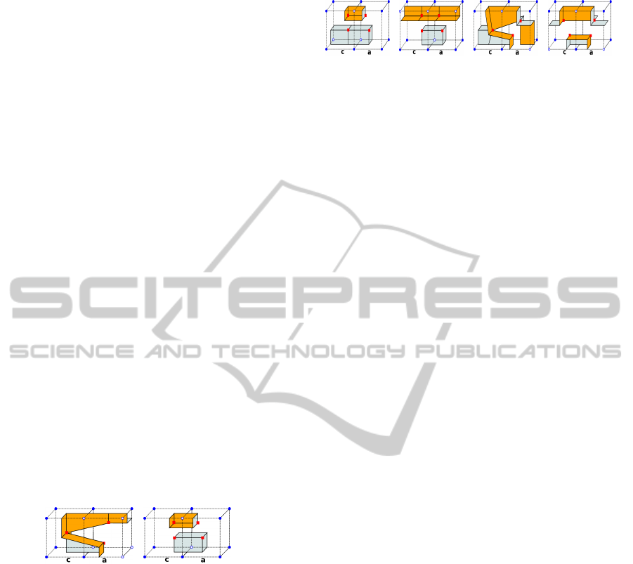
(a) (b)
Figure 2: Possible patches for two 6 solid vertices cells
connected by an ambiguous face. (a) solid component, (b)
empty component. Dual vertices are noted as red squares.
A cell with |S(c)| = 5 can have zero, one or three
ambiguous faces, the possible patches extracted with
our rules are illustrated in figure 3. The previous
criterion depends only on the connected components
of two neighbouring cells. As its application is lo-
cal, we have designed exhaustive tests which confirm
that, with our criterion, all non-manifold configura-
tions arising in DMC are correctly handled.
3.3 Octree Construction
As multi-resolution data structure, we have imple-
mented a linear octree that uses a Morton Code
(Lewiner et al., 2010). This code is a compact integer
(a) (b) (c) (d)
Figure 3: Pairs of cells sharing a common ambiguous face.
(a) and (b) Empty Connectivity, (c) and (d) Solid connectiv-
ity. Dual vertices are noted as red squares.
representation that allows us to encode hierarchical
relationships between octree cells together with geo-
metrical information about their position in the do-
main. Furthermore, a simple array can be used to
store octree cells in order to improve access times. As
our octree is generalized, we need to store initial and
final cell coordinates in ever octree cell, together with
cell corner’s values and the collapsed flag.
Our octree construction algorithm is an iterative
top-bottom algorithm that builds an octree until a
specified level of resolution. Octree cells are initially
divided if they are inhomogeneous and if it is not
complex as defined below.
Definition 5. Let C be a cell. C is complex if at least
one of its faces is complex. A cell face is complex if:
• It intersects F(x) and all its vertices are either in-
side or outside F(x).
• At least one of its edges intersects F(x) more than
once.
Complex cell criterion allows us to detect cells
that contain a piece of the surface that is smaller than
the current level of subdivision. This strategy allows
us to just check voxels that belongs to cell’s faces to
assure that all cells intersected by F(x) are going to
be processed.
Rule 5. Subdivision Rule: If a cell C is inhomoge-
neous or is complex, it has to be subdivided. Other-
wise, it is marked as an octree leaf.
The application of the subdivision rule will gener-
ate an octree where all leaves cells that intersect F(x)
are at the same level. Then, our dual vertex generation
rules (precedent section) can be applied in every cell
(ou pair of cells) to produce compact regular meshes.
3.4 Multi-resolution Meshes
In order to generate multi-resolution surfaces adapted
to the curvature of F(x). We propose to use a crite-
rion based on the normals at the intersection points
of cell edges with F(x). We have used a surface ap-
proach based on the measure of the average of unitary
normals in the neighbourhood of the edge intersection
with F(x) (Flin, 2005).
MULTI-RESOLUTION DUAL CONTOURING FROM VOLUMETRIC DATA
165

Criterion 1. Let C be a cell and I
i=0...n
its intersection
points with F(x). Let be n
i=0...n
the normals on I
i=0...n
.
If Max(n
i
• n
j
|i 6= j}) > δ, C must be subdivided. δ is
a user provided parameter with values in the closed
interval [0, 1].
The previous criterion gives valuable information
about the shape of F(x) inside the cell. As conse-
quence, a δ → 0 will produce an almost regular mesh.
On the contrary, δ → 1 will generate a highly simpli-
fied surface. This can lead to lose sharp features in
the generated surface. Cells that have not been sub-
divided until the maximal octree depth are marked
as collapsed. The octree creation method is imple-
mented iteratively and it is described in algorithm 1.
Algorithm 1: Build Octree algorithm.
input : Root cell of the octree c. Minimal level of the octree
minLevel and maximal subdivision level maxLevel.
output: Octree regular until level minLevel and adaptive between
minLevel and maxLevel.
Add cell c to toProcess list;
while toProcess is not empty do
currentCell ← GetFirstElement(toProcess);
if GetLevel(minLevel >= GetLevel(currentCell) And
currentCell) < maxLevel then
if isNotComplex(currentCell) then
if isNotPlanar(currentCell) then
Subdivide:
Comment: currentCell must be subdivided;
S = {q
1
, ..., q
8
} ← Divide(currentCell);
foreach cell q
i
in S do
Adds q
i
to the toProcess list
end
else Mark currentCell as a leaf and as collapsed
else Goto Subdivide
else Goto Subdivide
end
A collapsed cell can generate topological prob-
lems if it is adjacent to cells of higher resolution.
This is because at some resolution levels, the shape
of F(x) can traverse several times edges or faces of a
collapsed cell (see figure 4a) generating non manifold
configuration in the final surface.
(a) (b) (c)
Figure 4: Two neighbours cells are illustrated, blue spheres
are cells corners inside F(x). Collapsed cell (left) is in clair,
deeper cells are in dark. (a) Our algorithm detects a com-
plex face and subdivides the left cell (b), (c) The tunnel be-
tween cells is captured and a manifold surface is generated.
In order to solve this, we proceed as follows, for
each cell q marked as collapsed, we obtain its face ad-
jacent cells at the same level (see figure 4a in clear).
Then, for each adjacent cell, we extract the set of leaf
cells A
i
that are face adjacent to q. For each cell c ∈ A
i
,
we detect the face f ∈ c adjacent to q and we extract
the values of F(x) at its vertices. Doing it for all cells
in A
i
allows us to build a projection of F(x) over q’s
face as an image. Then, if any one of these face im-
ages are complex, a non manifold configuration will
be generated between these cells. Once the complex
topology has been detected, we decided to subdivide
q until complex faces are eliminated and the subdivi-
sion is good enough to capture the topology of F(x)
(see figure 4b and c).
However, other topological problems can be gen-
erated by q’s subdivision, so our algorithm recursively
checks if other cells have been affected and extends
the validation area. Our algorithm stops when no cell
presents complex faces. The resume of the method
can be seen in the algorithm 2.
Algorithm 2: Local refinement algorithm.
input : Set T of collapsed cells c. A level of refinement l.
output: Set A as the set of affected cells where T ⊂ A.
foreach cell c ∈ T do Add cell c to A ;
foreach cell c ∈ A do
Apply BuildOctree method to c until level l;
for f aceCounter ← 1 to 6 do
f ace ← GetCellFace (faceCounter);
if f ace is complex then
newA f f ectedCell ← GetAdjacentCell
(c,face);
Adds newAffectedCell to A ;
end
end
end
Algorithm 2 is executed recursively and its com-
plexity is linear over cells affected by any induced
subdivision. Its execution time strongly relies on the
topological complexity of F(x) but our experiments
have shown that no excessive subdivision is needed
to fix most topological problems. In our implementa-
tion, algorithm 2 is executed after the octree construc-
tion showed in algorithm 1.
3.5 Connectivity Generation
The connectivity generation process connects the dual
vertices by using a linear complexity algorithm, pro-
posed by (Ju et al., 2002), that traverses the octree
and connects the dual vertices of cells that share an
intersection-edge. The dual vertices are connected by
using the Rule 3 of our dual vertices generation algo-
rithm.
GRAPP 2012 - International Conference on Computer Graphics Theory and Applications
166
3.6 Dual Vertices Localization
We propose a dual vertex localization algorithm based
on the barycentre b
s
of every connected component
of F(x) inside a cell. Let be C a leaf cell in the octree
where F(x)∩C 6=
/
0. As we know the dimensions of C
and its mass M, we can obtain its barycentre b
c
. Then,
we calculate the barycentre of F(x) ∩C named b
s
and
its mass m
s
. Finally, the mass and barycentre of the
complementary of (F(x) ∩C) can be calculated using
equation Mb
c
= m
s
b
s
+ m
e
b
e
.
These three barycentre points and theirs cell’s
masses proportion can be used to approximate the po-
sition of the dual vertex d. Naturally, d will lie be-
tween b
s
and b
e
. This is illustrated in figure 5.
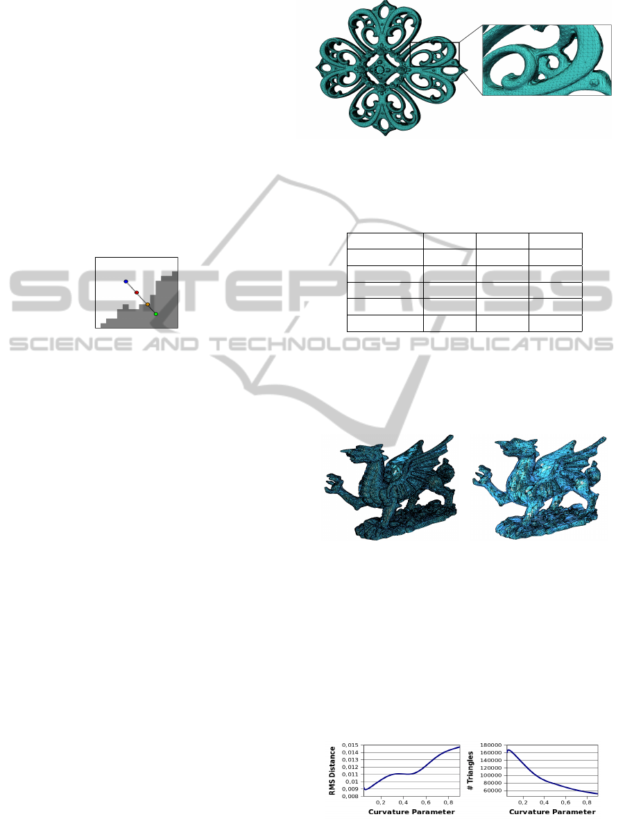
Figure 5: Cell barycentre (red), F(x)∩C barycentre (green),
(F(x) ∩C)
c
barycentre (blue), dual vertex (yellow).
Localization methods such as Quadric Error Func-
tions has been considered, however, QEF is not a
good estimator if the surface is noisy and our exper-
iments have shown that our method works well on
smooth or noisy surfaces.
4 RESULTS AND COMPARISON
Data sets presented in this paper were generated from
set of images extracted from the discretization of
polygonal meshes. As quality measures, we have
used the size of the mesh as number of triangles and
the Hausdorff and Root-Mean-Square distances with
respect to the discretized polygonal model.
4.1 Results
By applying our algorithm on multiple datasets, we
have confirmed that it always generates closed man-
ifold surfaces. An example is illustrated in figure 6
where a filigree model is generated from a 512
3
data
set with δ = 0.05 (curvature parameter) at 8 octree
depth. Table 1 shows generation times and distance
measures for the filigree model at different octree
depths. Relatively long execution times in the octree
construction phase of our algorithm are explained by
the cost of normals calculation and complex cell cri-
terion evaluation over discrete volumes.
(a) Filigree surface (octree depth 8) and zoom.
Figure 6: Filigree surface extracted at three octree depths 8
from a 512
3
volumetric model.
Table 1: Filigree dataset statistics at three octree depths.
Octree Level Depth 6 Depth 7 Depth 8
Octree Time 1.2s 3.142s 10.858s
Surface Time 2.767s 3.322s 8.099s
# Facets 15 266 66 438 255 088
RMS Dist. 0.006615 0.003103 0.001737
Hausdorff Dist. 0.024640 0.022805 0.008654
The δ parameter can be changed in order to produce
simplified multi-resolution meshes. In figure 7, Wales
Dragon meshes have been generated at the same oc-
tree level but with different curvature thresholds.
(a) Regular mesh (δ = 0.05). (b) Simplified mesh (δ =
0.9).
Figure 7: Wales Dragon surface generated from a volumet-
ric data set (512
3
) with a δ from 0.05 (a) to 0.9 (b), where
small triangles are just necessary in highly curved regions.
Graphs in figure 8 show that the model simplifica-
tion does not strongly affect the precision of our algo-
rithm. As it can be seen, we can reduce from 180K
triangles to less of 60K and geometrical error just in-
creases from 0.009 to 0.015 approximately.
Figure 8: RMS distance and number of triangles for Wales
Dragon data set with respect to the curvature parameter δ.
MULTI-RESOLUTION DUAL CONTOURING FROM VOLUMETRIC DATA
167
4.2 Comparison
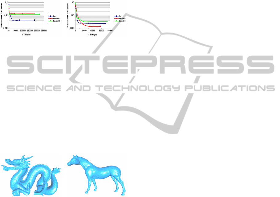
In order to compare our algorithm with relevant meth-
ods, we have chosen a MC based method (Kazh-
dan et al., 2007) and the implementation of the dual
method proposed by Schaefer and Warren (Schaefer
and Warren, 2005). Results for the Dragon and Horse
data sets are resumed in figure 9.
(a) Hausdorff Distance Vs
#Triangles in Dragon.
(b) Hausdorff Distance Vs
#Triangles in Horse.
Figure 9: Logarithmic comparison graphs between our
method (in blue), Schaefer et al. dual algorithm (in green)
and Kazhdan et al. MC algorithm (in red). For similar num-
ber of triangles, our algorithm leads to smaller or same or-
der error distances.
As it is shown in the graphs, with less triangles,
our algorithm is able to obtain better or as good ap-
proximations as Kazhdan and Schaefer. This is under-
standable because both methods are multi-resolution
extensions of MC and they restrict the surface nodes
to be located on the cell’s edges. surfaces produced
by our algorithm are shown in figure 10.
(a) Dragon. (b) Horse.
Figure 10: Dragon (182840 triangles) and Horse (70498
triangles) surfaces generated from 512
3
volumes with a 9
depth octree and a curvature parameter δ of 0.25.
5 CONCLUSIONS AND
PERSPECTIVES
In this paper we have presented a algorithm based on
Nielson’s DMC together with an efficient octree im-
plementation in order to generate compact and man-
ifold multi-resolution meshes. In addition, we have
proposed a dual vertex localization method based on
connected components to improve surface approxi-
mation. In further work, we believe that our approach
can be integrated on an Out-of-Core strategy in order
to process large volumetric data sets.
ACKNOWLEDGEMENTS
This research was partially supported by the French
National Project PEPS INS2I CNRS ImagEar3D.
Thanks to the Stanford CGL, Georgia Tech and Cy-
berware for the models used in this paper.
REFERENCES
Flin, F. (2005). Adaptative estimation of normals and sur-
face area for discrete 3d objects. IEEE Transactions
on Image Processing, 14(5):585–596.
Ju, T., Losasso, F., Schaefer, S., and Warren, J. (2002). Dual
contouring of hermite data. In Proceedings of SIG-
GRAPH ’02, pages 339–346.
Kazhdan, M., Klein, A., Dalal, K., and Hoppe, H. (2007).
Unconstrained isosurface extraction on arbitrary oc-
trees. In Proceedings of Symposium on Geometry pro-
cessing, pages 125–133.
Kobbelt, L. P., Botsch, M., Schwanecke, U., and Seidel, H.-
P. (2001). Feature sensitive surface extraction from
volume data. In SIGGRAPH ’01, pages 57–66.
Lewiner, T., Mello, V., Peixoto, A., Pesco, S., and Lopes, H.
(2010). Fast generation of pointerless octree duals. In
Computer Graphics Forum, volume 29, pages 1661–
1669.
Lorensen, W. and Cline, H. (1987). Marching cubes: A
high resolution 3D surface construction algorithm. In
SIGGRAPH ’87, volume 87, pages 163–169.
Manson, J. and Schaefer, S. (2010). Isosurfaces over sim-
plicial partitions of multiresolution grids. Computer
Graphics Forum, 29(2):377–385.
Nielson, G. M. (2004). Dual marching cubes. In Proceed-
ings of the conference on Visualization ’04, VIS ’04,
pages 489–496.
Schaefer, S., Ju, T., and Warren, J. (2007). Manifold dual
contouring. IEEE Transactions on Visualization and
Computer Graphics, 13:610–619.
Schaefer, S. and Warren, J. D. (2005). Dual marching cubes:
Primal contouring of dual grids. Computer Graphics
Forum, pages 195–201.
Varadhan, G., Krishnan, S., Kim, Y., and Manocha, D.
(2003). Feature-sensitive subdivision and isosurface
reconstruction. In Visualization, 2003., pages 99–106.
Varadhan, G., Krishnan, S., Sriram, T., and Manocha, D.
(2004). Topology preserving surface extraction using
adaptive subdivision. In Symposium of Geometry Pro-
cessing ’04.
Wang, C. and Chen, Y. (2008). Layered depth-normal
images for complex geometries-part two: manifold-
preserved adaptive contouring. ASME IDETC/CIE
Conference ’08.
Wilhelms, J. and Van Gelder, A. (1992). Octrees for faster
isosurface generation. ACM Trans. Graph., 11:201–
227.
GRAPP 2012 - International Conference on Computer Graphics Theory and Applications
168
