
FAST BEAD DETECTION AND INEXACT MICROARRAY PATTERN
MATCHING FOR IN-SITU ENCODED BEAD-BASED ARRAY
Soumita Ghosh
1
, Andreas Schmidt
1
and Dieter Trau
2
1
AyoxxA Living Health Technologies, Singapore, Singapore
2
Department of Bioengineering and Department of Chemical & Biomolecular Engineering,
National University of Singapore, Singapore, Singapore
Keywords:
Fast Inexact Graph Matching, Microarray Bead Detection, In-situ Encoded Bead-based Array, Graph Spectra,
Sequence Alignment.
Abstract:
This paper presents an automatic bead detection and bead array pattern matching technique developed for the
In-situ Encoded Bead-based Array (IEBA) technology. A supervised learning based bead detection technique
robust to irregular illumination variations and noise is developed. An efficient and effective graph matching
technique that combines graph spectral analysis and sequence alignment is used to match bead array patterns.
The matching algorithm proposed is rotation and scale-invariant. The pattern matching algorithm performs
in-exact matching and is capable of handling very large numbers of outliers in the target graph as well as large
number of occlusions in the template graph. The matching algorithm uses dynamic programming and can give
good time performances dependent only on the number of nodes in the template and target graphs, irrespective
of the number of outliers and occlusions. The algorithm can detect and match large number of beads in a few
seconds.
1 INTRODUCTION
With the rapid progress of life sciences in the last
decade various protein and DNA microarray formats
have emerged. All these technologies have the com-
mon goal of detecting and measuring multiple bio-
logical markers in the same sample - so called ”mul-
tiplexing”. They have become the preferred choice
when addressing complex questions in biomedical re-
search as well as when screening clinical blood sam-
ples for multiple infectious disease or cancer markers
at the same time in the same test. The latest gener-
ation of these ”biochips” include microscopic beads
immobilized on silicon chips. These beads are coated
with different biological agents like DNA-sequences
or antibodies that can each detect a distinct marker.
The central problem that remains is how to identify
which microscopic bead is measuring which analyte?
So far all commercial techniques use some kind of
physical label to identify the beads. To provide an
effective solution to multiplexing problem companies
around the world offer beads either in different shades
or colors or sizes or with tiny ”bar codes”. These ap-
proaches however make the process very tedious and
require expensive and bulky equipments such as flow
cytometers. Further using any kind of identifier lim-
its the multiplexing capacity. For example, if color is
used as the identifying marker then the multiplexing
capacity is limited by the available color labels that
can be robustly distinguished from each other.
In (Trau et al., 2008) the In-situ Encoded Bead-
based Array (IEBA) technology was introduced to
resolve the multiplexing issue in an effective way.
The IEBA technology identifies randomly distributed
beads on the biochip by obtaining the unique ”postal
code” of each bead without use of any other marker
on the beads. The postal code of each bead is the
unique spatial address of each bead. In this paper
we devise an algorithm using computer vision tech-
niques to detect the beads and identify them without
the use of any markers. Using such a marker less
method a higher multiplexing capacity (>1000) can
be achieved. The technique is developed using Ay-
oxxa Prokemion biochips. The chips contain multiple
wells, with each well comprising of a complete mul-
tiplex microarray. The detection of analytes on the
chip is based on a fluorescent signal. The quantitative
fluorescent signal can be obtained using a fluorescent
microscope, which is one of the most common equip-
ment in any research laboratory. Additionally vari-
ous high resolution fluorescent readers including au-
tomated high throughput screening lines used in in-
5
Ghosh S., Schmidt A. and Trau D..
FAST BEAD DETECTION AND INEXACT MICROARRAY PATTERN MATCHING FOR IN-SITU ENCODED BEAD-BASED ARRAY.
DOI: 10.5220/0003826800050014
In Proceedings of the International Conference on Computer Vision Theory and Applications (VISAPP-2012), pages 5-14
ISBN: 978-989-8565-04-4
Copyright
c
2012 SCITEPRESS (Science and Technology Publications, Lda.)

dustry can be used to generate the fluorescence pic-
ture files as test read-out. To simplify the whole pro-
cess we use a single fluorescent wavelength as a re-
porter for all analytes and all positive controls.
The analysis process involves finding correspon-
dence between two different kinds of images which
we call the manufacturing and fluorescent images.
The set of images acquired after each batch of bead
deposition during chip manufacturing are the manu-
facturing images and the set of images acquired af-
ter multiplex protein assay are called the fluorescent
images. The measurement and protein quantification
and analysis is carried out on these set of images. The
fluorescent picture shows the beads after reacting with
the different markers in the biological sample. The
beads light up, with their intensity of fluorescence be-
ing directly proportional to the concentration of a cer-
tain analyte. It then remains to uncover the identity of
the bead and find the biomarker it corresponds to.
Figure 1: The Ayoxxa Prokemion biochip. The chip has a
grid of circular wells. Each well is used for a sample.
The analysis process involves the following steps:
detecting the beads in the manufacturing and fluores-
cent images, tracing the region of the manufacturing
images that contains the fluorescent images and ob-
taining quantifiable measures like intensity and other
parameters from the fluorescent image to determine
the biomolecule that was attached to each individual
bead. The software developed fully automates this
analysis process. It uses two separate modules; one
for detection of the beads and the other for matching
between manufacturing and fluorescent beads. The
detection is done using a supervised learning tech-
nique while the matching uses spectral properties of
nearest-neighbour graphs and sequence matching al-
gorithms.
In order for the software to be commercially vi-
able both the detection and matching algorithms have
to be very accurate and efficient. Furthermore, the
algorithms have to be very robust to noise and other
external factors. In particular for fluorescent images,
since the environment under which they are captured
cannot be controlled the images produced may vary
in quality. Even slight variations in conditions may
affect the quality by a large amount. Some of the
common challenges involved in developing practical
bead detection algorithms are handling image noise
and irregular illumination. These can be caused by
the human involvement in the imaging process and the
imaging device setup. Further the microarray multi-
plexing technique is also not exact. Contaminations,
dust and excess solution sticking to the surface can in-
troduces impurities and make matching difficult. The
main contributions of this paper are firstly the devel-
opment of a practical and commercially viable bead
detection algorithm for the IEBA technology that can
detect beads of varying intensities and sizes under
heavy noise and non-uniform illumination and sec-
ondly the development of a fast graph matching al-
gorithm that can handle large mismatches and occlu-
sions in the graphs.
Once a match for the fluorescent image is found
in the manufacturing image, we also need to identify
those manufacturing beads which are present within
the matching region but do not have a corresponding
match in the fluorescent image. This is used to extract
information about the beads which were not captured
under fluorescence but were present on the chip sur-
face.
Section 2 gives a brief overview of the existing
commercially used bead detection techniques and the
available state-of-the-art pattern matching techniques.
In Section 3 we present the bead detection techniques
developed for identifying beads in the manufacturing
and fluorescent images. Then in Section 4 we present
the bead pattern matching technique. In Section 5
we present some performance results and in Sections
6 and 7 we draw conclusions and outline future im-
provements.
2 PREVIOUS WORKS
The most widely encountered problem in bead detec-
tion algorithms is that of irregular illumination. The
manufacturing images often have irregular illumina-
tion due to reflection from within the imaging envi-
ronment, due to external lighting or due to lens dis-
tortion. Insufficient drying of the chip surface before
capturing images can also causes solution droplets
to stick onto the surface and obstruct the bead pat-
tern layout beneath it, resulting in loss of valuable
information. Also, dust particles can get very heav-
ily illuminated causing nearby beads to be brighter
than usual. Figure 3 shows an irregularly illuminated
manufacturing image where the beads near the cen-
tre of the well are well focused and are brighter than
VISAPP 2012 - International Conference on Computer Vision Theory and Applications
6
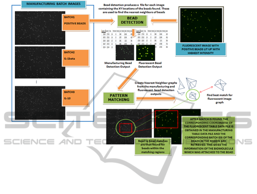
Figure 2: Illustrates the working of the system.
the ones near the edge of the well. Most commer-
cially used automatic bead detection algorithms do
not have to deal with such irregular illumination as
most of the bio chip techniques use complex imaging
devices that produce very high quality images. Fur-
ther, besides using high quality image capturing sys-
tems most other techniques also use expensive read-
ers to decode each bead uniquely. Some of the algo-
rithms that do handle such irregular illumination need
an additional pre-processing step to correct the image.
Other techniques such as (Oliveros and Sotaquir
`
a,
2007) use grids to simplify the detection process but
require pre-processing to handle rotation. Our bead
detection technique on the other hand does not use
any global parameters and performs bead detection
locally for each bead. Consequently the technique is
inherently rotation and scale invariant and very robust
against illumination variations and noise. Further to
allow for robust bead detection we use two different
kind of supervised learning techniques for the manu-
facturing and fluorescent images.
The main challenge in matching the fluorescent
image with the manufacturing image is that the scale
and orientation of the fluorescent image is unknown.
Therefore a scale and rotation invariant matching
technique is needed. Further since the bead detec-
tion algorithm cannot guarantee 100% accuracy there
is always the possibility of a few beads missing or a
few additional beads belonging to other batches be-
ing detected. Also as mentioned previously there is
always the possibility of additional bead like struc-
tures being present in the manufacturing images due
to contamination or dust. Therefore an exact match-
ing is inadequate for the problem. Most computation-
ally tractable point pattern matching algorithms as-
sume that either the template or the query set does not
have any noise. However in our case both the manu-
facturing and fluorescent image will have beads that
are not present in the other. Fig. 2 shows an example
of the bead detection and pattern matching process.
We formulate the problem of matching patterns of
beads as a graph matching problem. The problem
can be formally described as that of identifying the
largest common isometric subgraph that best matches
the template graph G (the manufacturing image bead
pattern) in the query graph G
0
(the fluorescent im-
age bead pattern).The problem of graph matching is
a quadratic assignment problem and is NP-hard. The
focus of graph matching research is therefore to ef-
fectively approximate the exact solution. In a recent
work (J.McAuley and S.Caetano, 2012) developed a
matching algorithm that gives good empirically for-
mulated results under noise. The algorithm however
has a major drawback. The complexity of the algo-
rithm is dependent on the number of missing beads in
the template graph. In our problem matching has to
FAST BEAD DETECTION AND INEXACT MICROARRAY PATTERN MATCHING FOR IN-SITU ENCODED
BEAD-BASED ARRAY
7
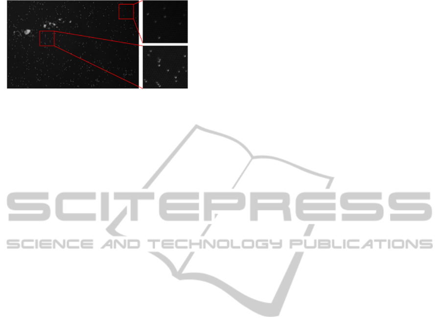
Figure 3: Shows an irregularly illuminated manufacturing
image. The beads close to the top right corner are less bright
due to lens distortion while the beads close to the noise are
brighter than the average beads because of the high lumi-
nance of the dust particles.
work even when as much as 25% of the beads in the
fluorescent image are missing.
Further the manufacturing image has thousands of
beads and an exhaustive search for scale and rotation
invariant match is impractical. Most fast graph match-
ing algorithms either performs only exact matching or
make too many assumptions (H.Alt and L.J.Guibas,
1996) and (Rezende and Lee, 1995). To perform inex-
act matching and still keep the time performance rea-
sonable we take a two step approach. First we use a
fast graph spectra based technique to identify regions
in the manufacturing image that are likely to have a
match for the beads in the fluorescent image. We then
use a more demanding sequence matching technique
to identify the most optimal bead to bead matches be-
tween manufacturing and fluorescent beads as well as
identify beads in each image which are missing in the
other.
Graph spectra is used to identify beads in the man-
ufacturing image which are similar to the beads in the
fluorescent image. Since the development of spectral
matching in (Leordeanu and Heberti, 2005) numerous
other graph spectra based graph matching techniques
such as (Cour et al., 2006) have been developed.
These techniques use the graph spectra of an assign-
ment graph whose nodes represent potential matches
between the template graph (G) and query graph (G
0
)
nodes and whose edge weights represent the potential
agreement between match pairs. The Eigenvalue de-
composition of the assignment graph has a time com-
plexity of O(|G|
3
|G
0
|
3
). This prohibitively high time
complexity restricts the use of spectral techniques to
matching smaller graphs. We avoid this problem by
using graph spectra only as a local descriptor.
The estimation of the location of a bead in both the
fluorescent and the manufacturing images can have
some errors and therefore an error tolerant matching
is necessary. We use the tolerance estimation tech-
nique used in (Evans and Tay, 1995) to estimate the
tolerance values for each spectral feature individually
from a training dataset.
The Smith-Waterman algorithm (Smith and Wa-
terman, 1981) is used in the second step to find the
most optimal set of bead to bead matches. The Smith-
Waterman algorithm was originally developed for
finding common molecular subsequence and there-
fore has to be modified slightly for use in our match-
ing problem. The algorithm is implemented using dy-
namic programming and has a complexity of O(mn)
where the sequences to be matched are of length m
and n. Smith-Waterman algorithm has also been used
previously for shape matching in (Chen et al., 2008)
and (Riedel et al., 2006). It has the nice property that
it produces the optimal local alignment with respect
to the scoring system.
3 BEAD DETECTION
3.1 Manufacturing Bead Detection
In order to overcome the irregular illumination prob-
lem we use a local adaptive thresholding technique.
The thresholding is performed by calculating the in-
tensity distribution of small square patches in the im-
age and thresholding out the highest 5% of the inten-
sities. A sliding window with no overlap is used to
threshold the entire image. The size of the patches is
about 10 times the normal diameter of beads. This al-
lows a very optimistic thresholding i.e. it tries to iden-
tify beads everywhere. Even for large illuminated ar-
eas the algorithm extracts only the brightest regions.
The normal diameter of beads is learnt from the ra-
dius feature described later and the 5% cut-off is esti-
mated empirically. Contour detection is then applied
on the binary images using algorithm developed by
(S.Suzuki and K.Abe, 1985). The regions of the man-
ufacturing image fully enclosed by each closed con-
tour are then extracted. The maximum intensity and
mean location (mean x and y coordinates) of each
region is calculated. The locations are then used as
seeds for region growing while the maximum intensi-
ties are used to estimate the intensity threshold to stop
the region growing.
Small amount of region dilation is then performed
for each region using a circular structuring element of
radius 3 pixels to make the edges smooth.
Following this for each region the following set
of shape, size and intensity features are extracted:
Area, Perimeter, Intensity Sum, Intensity Mean, In-
tensity Variance, Minimum Intensity, Maximum In-
tensity, Radius Mean, Radius Variance, Minimum Ra-
dius, Maximum Radius and Orientation. Where the
area and perimeter features are the number of pixels
inside the region and on the contour respectively. The
VISAPP 2012 - International Conference on Computer Vision Theory and Applications
8

area and perimeter features deal with both size and
shape of the feature. For e.g. a very large perimeter
for a small area is indicative of a rough contour or a
concave region. The Intensity Sum, Intensity Mean,
Intensity Variance, Minimum Intensity, Maximum In-
tensity features deal with the intensity distribution of
the region. The sum of intensities and mean are in-
dicative of the overall brightness of the region. The
intensity variance and minimum and maximum inten-
sities are indicative of the overall change in intensity
from the centre of the region to the edge of the re-
gion. A very high variance in intensity or a large max-
imum intensity to minimum intensity ratio is indica-
tive of an unevenly bright spot. The radius mean, ra-
dius variance, minimum radius, maximum radius are
calculated as the mean, variance, minimum and max-
imum respectively of the distances from the centre of
the region to each contour pixel. The Radius mean
and radius variance features also deal with the overall
shape of the region. True beads tend to show a slightly
oval shape and therefore have a moderate radius vari-
ance and a rather stable minimum to maximum radius
ratio. For any particular manufacturing image, beads
are also found to be oriented in the same way. The
orientation feature is used to encapsulate this prop-
erty. It is calculated as the angle the longest axis of
the region makes with the y-axis.
A binary one-to-one support vector machine is
then trained using the above 12 features to classify
the extracted regions as bead and non-bead regions.
Classification results are presented in Section 5.
3.2 Fluorescent Bead Detection
The same set of features as the ones extracted for de-
tecting manufacturing beads are also extracted for flu-
orescent bead detection. However for the final classi-
fication instead of using a single support vector ma-
chine a number of support vector machine classifiers
are trained. This is necessary because beads of differ-
ent batches in the manufacturing process differ heav-
ily in appearance in both size and intensity. Further
estimating the batch of the bead directly from the
intensity becomes a multi-class classification prob-
lem which can significantly reduce the accuracy, even
when classification is done by max-wins voting strat-
egy. For our particular problem we found that training
a single one-versus-all support vector machine classi-
fier for each batch gave the best results.
4 BEAD PATTERN MATCHING
Once the bead patterns and their respective batches
have been estimated the relative locations of beads is
used to find matches. For a particular batch the inten-
sity, shape, size and orientation of all beads are very
similar and therefore these features cannot be used to
distinguish between them. The only feature that dis-
tinguishes a bead is the relative position of other beads
with respect to that bead. That is the pattern formed
by the neighbours of a bead is the identifier of the
bead.
The bead matching is done in two steps. In the first
step the graph spectra of the fully connected weighted
graph formed using the bead and its 3 nearest neigh-
bours is used to find a region of the manufacturing im-
age that is most likely to have a matching pattern. The
spectrum of the affinity matrix of a graph has the nice
property of being invariant to rotation and labelling.
This allows the first step of the matching to be rota-
tion invariant. Further using the normalized Laplacian
of the graph instead of the adjacency matrix makes
the matching invariant to scale. The edge weights
are simply the Euclidean distance between the bead
centres. The graph spectra is calculated by doing an
Eigen value decomposition of the normalized graph
Laplacian. The graph Laplacian is calculated as fol-
lows:
L(u, v) =
1, if u = v
−w(u,v)
√
d
u
d
v
, if u and v are adjacent
0, otherwise
(1)
where
d
u
=
∑
v
w(u, v) (2)
and w(u, v) is the weight of the edge between nodes u
and v.
The choice of the number of nearest neighbours
depends on the amount of mismatch in the graphs.
For our implementation the value of 3 was chosen em-
pirically. Using 3 nearest neighbours means that in
order to find a correct match there should be at least
one bead in the fluorescent image for which its 3 near-
est neighbour pattern matches the 3 nearest neighbour
pattern of its true corresponding bead in the manufac-
turing image. This is a reasonable assumption partic-
ularly for dense patterns. In case of sparse patterns us-
ing even 2 nearest neighbours produced good results.
Using a small number of nearest neighbours is nec-
essary because in this step we intend to find matches
which are very similar to each other. In particular we
try to find matches where nodes are not missing and
differences in the two graphs are only because of er-
ror in determining the location of the beads during the
detection process. This step however provides many
possible matches and is used to locate the regions
of the manufacturing image that is likely to have the
FAST BEAD DETECTION AND INEXACT MICROARRAY PATTERN MATCHING FOR IN-SITU ENCODED
BEAD-BASED ARRAY
9

matching pattern. Further the matching is extremely
fast because of the small size of the graph Laplacian.
The Eigen decomposition of the 4x4 graph Laplacian
gives 4 Eigen values. The first Eigen values deals with
the scale of the graph and since we are interested in a
scale invariant match it is ignored. The remaining 3
Eigen values are used to find the matches. Matching
the 3-tuple graph spectra of two graphs is done using
a tolerance value for each dimension. The tolerance
value for each dimension is calculated as the standard
deviation of that dimension for true matches and is es-
timated using a training dataset.
The graph spectra based matching produces a set
of possible matches in the manufacturing image for
each fluorescent bead. These possible matches are
then further refined in the second step using a larger
set of nearest neighbours and a sequence matching
technique. The nearest neighbours of a bead in this
step are defined as a set of distance-angle pairs in-
stead of just distances. The angle for the kth nearest
neighbour is calculated as the angle formed between
the line connecting the bead to its first nearest neigh-
bour and the line connecting the bead to its kth nearest
neighbour. This allows the matching to be rotation in-
variant. In order to make the matching scale invariant
the distances are normalised by dividing all distances
by the distance to the first nearest neighbour. The
sequences are finally formed by sorting the distance-
angle pairs first by distance and then by angle.
A slightly modified version of the Smith-
Waterman sequence alignment algorithm is used to
find the match between nearest neighbour sequences
for each fluorescent-manufacturing bead match found
in the first step. Instead of doing exact matches of
characters as in the original Smith-Waterman algo-
rithm an error tolerant matching of distance-angle
pairs is used where some tolerance is allowed for both
the distance and angle values. In this case however
the effect of tolerance is much less significant because
of the use of both the angle and distance. The score
matrix for two sequences a and b of lengths m and n
respectively is defined as:
H(i, j) =
0, if i = 0 or j = 0
max
0,
H(i −1, j −1) +w(a
i
, b
i
),
H(i −1, j) +w(a
i
, −),
H(i, j −1) + w(−, b
i
)
else
(3)
where
w(a
i
, b
i
) =
(
match score, if a
i
= b
i
,
mismatch score, otherwise
(4)
and
w(a
i
, −) = w(−, b
i
) = gap score (5)
The values for gap score, match score and mis-
match score were empirically found to be -9.0, 10.0
and -8.0 respectively. The Smith-Waterman algorithm
however does not guarantee an exact match for each
element of the sequences. For instances for two se-
quences of distance-angle pairs shown in table 1 be-
low:
Table 1: Example sequence.
A 119,7.47 166,7.19 321,5.22 60,4.98
B 127,7.59 166,7.23 35,6.13 60,5.01
Smith-Waterman algorithm can produce an align-
ment as shown below:
Table 2: Example sequence alignment.
119,7.47 -
- 127,7.59
166,7.19 166,7.23
321,5.22 35,6.13
60,4.98 60,5.01
Since we are interested only in finding exact
bead to bead matches an additional correction step is
needed which identifies mismatches in the aligned se-
quences such as the one in the 4th row of table 2 and
changes the sequence alignment to correct them.
The best matching fluorescent and manufacturing
bead pair is identified as the one that gives the high-
est percentage of matching distance-angle pairs. In
case more than one fluorescent and manufacturing
bead pair produces the same percentage of distance-
angle pair matches, the one with the smallest sum
of squared error is defined as the best match. The
sequence matching directly gives the bead to bead
matches for all fluorescent image beads as well as
gives the manufacturing and fluorescent beads for
which matches were not found.
Finally, the scale and rotation of the matching pat-
tern are estimated as the modes in the ratio of dis-
tances and the difference of angles between the flu-
orescent and its corresponding manufacturing bead.
Once the scale and rotation angle have been esti-
mated the missing fluorescent beads are located by
back tracking their location in the manufacturing im-
age.
5 RESULTS
Testing was performed on a set of manually labelled
manufacturing and fluorescent images. For testing
detection performance artefacts in both manufactur-
ing and fluorescent images were manually labelled as
VISAPP 2012 - International Conference on Computer Vision Theory and Applications
10

beads and non-bead artefacts. For quantifying the pat-
tern matching performances the most optimal match
for each fluorescent image’s bead pattern was man-
ually found in a set of manufacturing images and the
exact bead to bead matches were also manually found.
To evaluate the performance of the detection algo-
rithm the specificity, sensitivity, precision and accu-
racy of detection were used.
For testing detection accuracy on fluorescent im-
ages bead detection was performed on a set of 40 fluo-
rescent images acquired under different experimental
conditions over a long period of time. Table 3 shows
the detection results for a 10-fold cross validation on
fluorescent beads. For fluorescent images the detec-
tion algorithm shows high accuracy and precision and
as well as high specificity and sensitivity.
Table 3: 10-fold cross validation results of detection on a
set of 40 fluorescent images.
Performance Measure Mean Standard Deviation
Sensitivity 0.974 0.016
Specificity 0.988 0.015
Accuracy 0.980 0.003
Precision 0.993 0.009
Bead detection was also evaluated on 20 manu-
facturing images. The images were acquired under a
large range of conditions and the dataset was designed
to have images with large variations in noise levels as
well as irregular illumination levels. Typically manu-
facturing images have a very large number of beads
(>500) and therefore manually identifying all pos-
itive and negative beads is extremely tedious. The
data set used here for example contained over 10000
beads. Therefore to generate the labelled data a semi-
supervised technique was used. A naive Bayes classi-
fier was trained to classify the most obvious beads as
true beads. This classifier was trained very conserva-
tively and therefore high confidence could be put on
its positive results. In essence whenever the classifier
found even slight variations in the features with re-
spect to the features of the positive class it classified
the bead as negative. An interface was also devel-
oped that allowed the program to sequentially present
beads identified by the naive Bayes classifier as nega-
tive to the user for manual classification.
Table 4 shows the performance results for manu-
facturing bead detection. The algorithm achieves high
specificity and sensitivity as well as high accuracy and
precision even for manufacturing images. The sensi-
tivity in the case of manufacturing image is however
slightly lower than that of fluorescent images as the
percentage of actual beads to the total number of arte-
facts in the image is much smaller and this bias in-
creases the number of false negatives.
Table 4: 10-fold cross validation results of detection on a
set of 20 manufacturing images.
Performance Measure Mean Standard Deviation
Sensitivity 0.919 0.019
Specificity 0.997 0.003
Accuracy 0.973 0.006
Precision 0.993 0.008
To test the robustness of the algorithm against
noise simulated noisy manufacturing images were
generated by adding Salt and Pepper noise to the orig-
inal images. Adding salt and pepper noise has two
effects, first it arbitrarily changes the shapes of the
true beads and second when large amount of noise
is added, artificial artefacts similar to real noise pat-
terns caused by dust particles are formed. Figure 4(a)
shows a section of a manufacturing image and figure
4(b) shows the same section with 10% noise added
to it. Detection was performed on a set of 5 manu-
facturing images with each image having 6 instances
with different levels of noise added. Figure 5 shows
the detection performance on the set of images with
respect to different levels of noise. The detection al-
gorithm shows good resistance against noise and is
able to handle noise as high as 10%.
To test detection performance against irregular il-
lumination synthetic manufacturing images were cre-
ated from the original images by adding a grayscale
gradient map. Figure 6(a) shows an original manu-
facturing image and figure 6(b) shows the synthetic
image constructed by adding a gradient map with
mean intensity of 128 and 50% opacity to the orig-
inal image. Figure 7 shows the detection perfor-
mance against different levels of irregular illumina-
tion. As can be seen both form the detection out-
put in figure 6(b) and in figure 7 the algorithm is ca-
pable of handling very large amount of illumination
variations. The number of false positives starts to in-
crease sharply at 40% opacity while at the same time
the number of false negatives reduces significantly as
more and more artefacts in the image are extracted
and classified. This effect can be seen in figure 7
where the specificity starts to increase as opacity is
increased beyond 40%.
Pattern matching performance is evaluated on 5
sets of 3 manufacturing and 3 fluorescent images.
For each fluorescent image a match is found in one
of the three manufacturing images giving a total of
15 pattern matches. Together the 15 fluorescent im-
ages contain over 700 beads for which bead to bead
matches were detected. The fluorescent bead patterns
to be matched vary heavily in bead density and in
the number of beads within the pattern actually hav-
ing a match in the manufacturing image. The true
FAST BEAD DETECTION AND INEXACT MICROARRAY PATTERN MATCHING FOR IN-SITU ENCODED
BEAD-BASED ARRAY
11
(a)
(b)
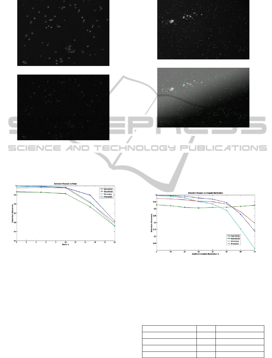
Figure 4: (a) shows the original section of a manufacturing
image and (b) shows the same section with 10% salt and
pepper noise. Here 10% noise means 10% of the pixels
have been randomly set to the mean intensity of beads.
Figure 5: Shows the change in Specificity, Sensitivity, Ac-
curacy and Precision with changing noise levels.
positives in this case are identified as correct bead
to bead matches for all beads within the bounding
region of the matching patterns (for fluorescent im-
age this means the entire image). This includes pre-
dicted matches for manufacturing beads not present
in the fluorescent image that is beads that did not re-
act or were not detected. True negatives are those
beads in the fluorescent image which are missing in
the manufacturing image and for which a match was
not found. These are the beads that were activated
because of contamination. False positives are incor-
rectly identified bead to bead matches while false neg-
atives are fluorescent image beads which do not have
a true match in the manufacturing image but a match
was detected. Once again we use specificity, sensi-
(a)
(b)
Figure 6: (a) shows the original manufacturing image and
(b) shows the bead detection output on the same image with
50% gradient. Here 50% gradient means a gradient map
with mean intensity of 128 and 50% opacity has been ap-
plied to the original image. The detection algorithm output
is evenly distributed irrespective of the illumination level.
However, at this level of irregularity the false positive rate
of detection starts to increase sharply.
Figure 7: Shows the change in Specificity, Sensitivity, Ac-
curacy and Precision with changing levels of irregular illu-
mination.
tivity, precision and accuracy to evaluate the match-
ing performance. Table 5 shows the results for the 15
matches.
Table 5: Bead to bead matching results for 15 fluorescent
image patterns.
Performance Measure Mean Standard Deviation
Sensitivity 0.382 0.185
Specificity 0.988 0.010
Accuracy 0.923 0.021
Precision 0.931 0.022
The results show good sensitivity, accuracy and
VISAPP 2012 - International Conference on Computer Vision Theory and Applications
12
precision but a strikingly low specificity. This is be-
cause of a large bias towards the positive class. Typi-
cally most fluorescent beads have a true match in the
manufacturing image and only very few beads in the
fluorescent image are those which reacted and bright-
ened up due to contamination. Therefore although the
Precision is high the number of false positives is com-
parable to the number of true negatives and false neg-
atives.
Fluorescent images of higher batches tend to have
very high bead densities and a larger mismatch can be
found between the fluorescent image beads and the
actual matching manufacturing beads. Beads that lit
up due contamination and beads that did not react or
were not detected can together cause the true match-
ing regions in the two images to have less than 30%
of the matching beads. Matching under such heavy
occlusion conditions and with outliers is one of the
strengths of this algorithm. To evaluate the matching
performance under such conditions simulated data is
created by adding and removing beads to the fluores-
cent images and to the region of the manufacturing
image containing the true match. The results of test-
ing on a set of 15 fluorescent manufacturing image
pairs is shown in figure 8. The amount of mismatch
is quantified as the ratio of synthetic beads added and
original beads removed to the number of total match-
ing beads.
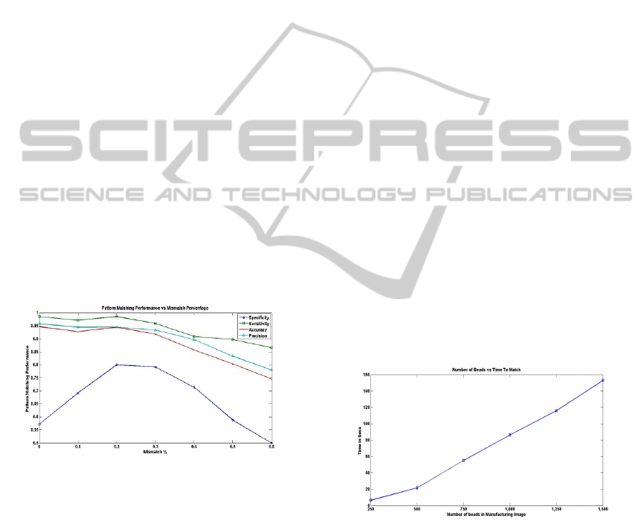
Figure 8: Shows the change in Specificity, Sensitivity, Ac-
curacy and Precision with changing levels of mismatch be-
tween the fluorescent bead pattern and the manufacturing
bead pattern. Here the amount of mismatch is quantified as
the ratio of the sum of synthetic beads added to the fluores-
cent image and manufacturing beads removed to the number
of total manufacturing beads with true bead to bead match
in the fluorescent image.
Similar to the results in table 3 the specificity is
low in figure 8 as well. However as the amount of
mismatch increases initially the specificity also in-
creases as more instances of the negative class are
added to the data and therefore the bias towards the
positive class decreases. However after a certain level
of mismatch all the performance measures start de-
clining sharply. This is due to the cases where overall
matching fails all together. The matching algorithm
requires at least one bead with similar 3-NN struc-
ture in both the fluorescent and manufacturing image.
As the mismatch exceeds 30% this is not satisfied in
some cases. Similarly even at very high mismatches
such as 60% in some cases true matches are found.
In general however when the 3-NN criterion is satis-
fied very high sensitivity, precision and accuracy are
achieved.
Another major strength of this algorithm is that
it is fast and scales well with increasing size of
the graphs. State-of-the-art graph matching algo-
rithms that can deal with occlusions and outliers have
quadratic or quasi-quadratic complexity. Our algo-
rithm on the other hand has almost linear complex-
ity. The time performance of the algorithm was evalu-
ated on a manufacturing data set with 6 images where
each subsequent image had greater number of beads.
Matching was performed for 5 fluorescent images
with number of beads ranging from 70 to 80. Test-
ing was done on a workstation with Pentium Core 2
duo 2.1 GHz processor with 2.0 GB RAM. Figure 9
shows that the time taken to match increases almost
linearly with the number of beads in the manufactur-
ing images. This is because most of the matching is
done using graph spectra and calculating the spectra
of a 4x4 matrix is extremely fast. The number of pos-
sible matches identified using graph spectra also does
not increase rapidly with increasing number of nodes.
When the number of beads range from 250 to 500,
which is the most significant range for us the time
taken to match is between 6 to 20 seconds.
Figure 9: Shows the time taken to find a match with increas-
ing graph sizes.
6 CONCLUSIONS
The future of the healthcare lies in ’Personalized
Medicine’ which tailors the medical treatment of an
individual based on his/her profile characteristics (Pri-
orities for Personalized Medicine, 2008). This is ben-
eficial in many ways as treating all patients in the
same way not only ignores the individual conditions
FAST BEAD DETECTION AND INEXACT MICROARRAY PATTERN MATCHING FOR IN-SITU ENCODED
BEAD-BASED ARRAY
13

and specific therapy requirements of each individual
but also incurs excess cost to the healthcare system.
Improvement in healthcare system requires
closer collaboration with technologies from multi-
disciplinary background. Use of advanced computer
vision and machine learning techniques are of
vital importance to resolve many issues in medical
applications. In present days no technology can be
isolated from the other in creation of a successful
commercially viable product. The bead detection
and pattern matching algorithm developed here
specifically solves some of the problems such as
handling noisy image data, irregular illumination
and occlusion and outlier resistant pattern matching
involved in the IEBA technology. The IEBA technol-
ogy together with automated fast bead detection and
inexact microarray pattern matching effectively uses
computer vision and machine learning algorithms
and promises to be an excellent platform for protein
multiplexing and take medical diagnostics to the next
level.
REFERENCES
Chen, L., Feris, R., and Turk, M. (2008). Efficient partial
shape matching using smith-waterman algorithm. In
In CVPR workshop on Non-Rigid Shape Analysis and
Deformable Image.
Cour, T., Srinivasan, P., and Shi, J. (2006). Balanced graph
matching. In NIPS.
Evans, D. J. and Tay, L. P. (1995). Fast learning artificial
neural networks for continuous input applications. In
Kybernetes.
H.Alt and L.J.Guibas (1996). Discrete geometric
shapes:matching,interpolation,and approximation: A
survey. In Technical Report, Handbook of Computa-
tional Geometry.
J.McAuley, J. and S.Caetano, T. (2012). Fast matching of
large point sets under occlusions. In Pattern Recogni-
tion 45 (2012). Elsevier.
Leordeanu, M. and Heberti, M. (2005). A spectral tech-
nique for correspondence problems using pairwise
constraints. In ICCV.
Ng, J. K., Selamat, E. S., and Liu, W.-T. (2008). A spatially
addressable bead-based biosensor for simple and rapid
dna detection. In Biosensors & Bioelectronics. Else-
vier.
Oliveros, A. and Sotaquir
`
a, M. (2007). An automatic grid-
ding and contour based segmentation approach ap-
plied to dna microarray image analysis. In Interna-
tional Journal of Biological and Life Sciences.
Priorities for Personalized Medicine (2008). (PCAST
2008). Technical report, Presidents Council of Ad-
visors on Science and Technology.
Rezende, P. and Lee, D. (1995). Point set pattern matching
in d-dimensions. In Algorithmica 13(1995).
Riedel, D. E., Venkatesh, S., and Liu, W. (2006). A smith-
waterman local alignment approach for spatial activity
recognition. In In Proceedings of AVSS’2006.
Smith, T. F. and Waterman, M. S. (1981). Identification
of common molecular subsequences. In Journal of
Molecular Biology.
S.Suzuki and K.Abe (1985). Topological structural analysis
of digital binary image by border following. In Com-
puter Vision, Graphics, and Image Processing, Vol.
30, No. 1.
Trau, D., Liu, W.-T., and Ng, J. K. K. (2008). A microarray
system and a process for producing microarrays. In
International Publication Number WO 2008/016335
A1.
VISAPP 2012 - International Conference on Computer Vision Theory and Applications
14
