
A VERSATILE SIMULATED REALITY FRAMEWORK
From Embedded Components to ADAS
Sebastian Noth
1
, Johann Edelbrunner
1
and Ioannis Iossifidis
2
1
NISYS GmbH, Universit
¨
atsstr. 142, 44799 Bochum, Germany
2
HRW University of Applied Sciences, Mellinghofer Strae 55, 45473 M
¨
ulheim an der Ruhr, Germany
Keywords:
Driving Simulation, Virtual Reality, ADAS, Driving Behaviour.
Abstract:
The developmental process of any kind of systems, either single embedded components or complex composite
system like ADAS, is supposed to reflect all constraints of the desired task and boundary conditions of the en-
vironment in order to be part of the solution. Advanced driver assistant systems acting in natural unstructured
environments, interacting with human operators, define the highest level of complexity, and the demanded
requirements can only be met by a simulated environment providing the best possible approximation of the
reality. In this contribution we introduce a versatile simulated reality framework allowing to develop, asses and
benchmark embedded components, whole ADAS, related network interactions and models of human driving
behavior.
1 INTRODUCTION
In the context of increasing complexity of urban traf-
fic, the development of autonomously acting embed-
ded components, on a local scale inside cars and as in-
terconnected pervasive network on a global scale, im-
plementing self organizing mechanism able to handle
global traffic situation, provide appropriate solutions
to nowadays demands on safety and comfort.
From the single component to the pervasive net-
work the community faces the complex problem to
develop, asses and benchmark such components in
environments containing same variances as real world
and providing ground truth of all parameters. Ad-
vance Driver Assistant Systems (ADAS) add another
level of complexity by incorporating human driving
behavior, which has to be modelled as well.
Models describing the underlying processes re-
quire experimental data able to identify and to mea-
sure relevant parameters. The fact that perception, el-
ementary action skills and the related representation
of the system to be observed are tightly coupled, re-
quires in addition an experimental environment capa-
ble of varying relevant scene parameters and record-
ing ground truth data while performing demanded ac-
tions. Although implementation on real hardware is
of mandatory importance for the proof of concepts,
the operational overhead is a limiting factor for the
development, optimization and assessment of embed-
ded components and models.
It seems obvious that the required tests could
not be accomplished within a real traffic situation.
Ground truth is not available in to the required ex-
tent, recording statistically significant data would take
many years, and the demanded boundary conditions
of the predefined test cases could lead to dangerous
situations. The described requirements can only be
met by a simulated reality framework incorporating
human subjects in the loop.
Researchers over the world are using or develop-
ing simulation software focusing mainly on particular
aspects of traffic flow modeling. In general, we dis-
tinguish between macroscopic and microscopic traffic
simulators (Gowal et al., 2010; Lochert et al., 2005;
Peh et al., 2002; Schroth et al., 2005; Yang and Kout-
sopoulos, 1996). Mostly designed to study flow or
network properties without incorporating on-line in-
teraction of autonomously behaving agents or real hu-
man subjects. Both types of simulation are out of the
scope of our objectives due to the fact that individual
behaviors cannot be captured, and thus the analysis
of the implications of single intelligent vehicle in the
context of standard traffic situation is not possible.
In this work we introduce a versatile simulator
and assessment framework which implements realis-
tic sensorial input, human driver models, physically
plausible behaving objects and the option to incor-
porate human subjects. With respect to experiments
177
Noth S., Edelbrunner J. and Iossifidis I..
A VERSATILE SIMULATED REALITY FRAMEWORK - From Embedded Components to ADAS.
DOI: 10.5220/0003825301770187
In Proceedings of the 2nd International Conference on Pervasive Embedded Computing and Communication Systems (PECCS-2012), pages 177-187
ISBN: 978-989-8565-00-6
Copyright
c
2012 SCITEPRESS (Science and Technology Publications, Lda.)

with humans, driving inside the simulator, a realistic
visual feedback and the feeling of being immersed in
the virtual scene is crucial for the collection of driv-
ing data. We utilized a self developed head tracking
system in order to improve humans immersion (Noth
et al., 2010). The following sections describe the
structure and software modules in details and demon-
strate in several show-cases the performance of the
overall system.
2 SOFTWARE ARCHITECTURE
A software that shall be a useful and reliable testing
tool needs to satisfy several requirements: A stable
and robust core, which does not need to be changed
as a reaction to additional demands and new trends,
is crucial. The software needs to be flexible in order
to easily incorporate new features or to replace com-
ponents without changes affecting the core and unre-
lated parts of the system. It should use proven de-
sign concepts and build upon state-of-the-art libraries
in order to avoid reinventing the wheel. All modules
should be tested under hard conditions. In the fol-
lowing, we explain how we meet these high demands,
which are imposed not only by ourselves, but also by
the application itself - an ADAS needs to be almost
fail safe.
TrafficSimulation is a pure C++ project. It uses es-
tablished libraries and frameworks like boost, QT and
OpenSceneGraph. It uses CMake as a tool for manag-
ing the project packages. It is tested under Windows
and Linux.
TrafficSimulation has a strongly modularized
structure, which facilitates development and mainte-
nance of existing functionality and makes the creation
of new components easy.
2.1 Discrete Event Simulation
TrafficSimulation is a multi threaded discrete event
simulation: Events are executed in their chronologi-
cal order, if possible (but not necessarily) in parallel.
During a specific event, a specific portion of data is
modified. The component of TrafficSimulation that
contains the queue and processes the events is the
Scheduler class (see 3.1).
Events always relate to one particular simulator
module, eg. the road module, the network module, or
the render module. An individual event in this sense
is basically a call to a function that changes the part of
the simulation’s state data that is associated with the
respective module.
At initialization time, one event is added to the
event queue for each module. After execution, which
has to be implemented in the update() function, of
each event, the respective module computes the start
time for its succeeding event. The next event is then
inserted into the queue. The consequence of this
is that the sum of currently processed and pending
events is always constant.
2.2 Central Update Loop
In addition to working off the scheduler’s event
queue, the application has to process operating sys-
tem events (eg. user input), so the Scheduler executes
only a chunk of events at any one time. After that, ex-
ecution of the simulation is interrupted shortly in or-
der to process the system events. For some cases (eg.
pressing a keyboard key), a system event triggers an
inter-module event (see 3.6). During the central up-
date loop, the relation between simulation clock and
system clock speed is computed, and the main display
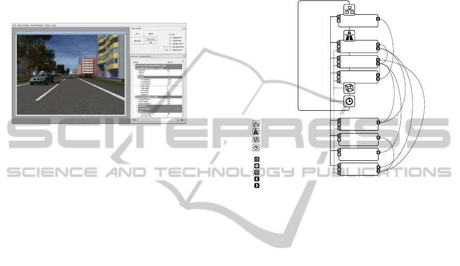
(see Fig. 1) is also refreshed.
Figure 1: Main control user interface of TrafficSimulation.
The most relevant control buttons are arranged next to the
most relevant information.
2.3 TrafficSimulation Modules
The code of TrafficSimulation is divided into func-
tional modules that share some general properties.
Each module:
• implements an update() function, which repre-
sents the central computation
• implements a notify() function, which is called
in order to tell about global events
• possesses a configuration object
• may possess a buffered state data object
• may possess data dependencies to other state data
of other modules
• may provide a scene graph node which is inte-
grated into the scene graph
Four modules are indispensable for TrafficSimu-
lation (see 4). They are loaded and initialized dur-
PECCS 2012 - International Conference on Pervasive and Embedded Computing and Communication Systems
178
ing the application start. Functionality of these mod-
ules is available to all other modules through the Core
component, eg. the scene graph provided by the Ren-
der Module, road geometry data provided by the Road
Module etc.
All other modules (see 5) are optional, they can
be plugged to TrafficSimulation and are hence called
plug-ins.
Figure 2: Screen shot of TrafficSimulation with one camera
window and the user interface visible.
2.4 Batch Mode and Incremental
Configurations
In its general operation mode, TrafficSimulation runs,
once started, until it is manually stopped. In addi-
tion, it is possible to restrict execution until a de-
fined mileage has been reached by the reference ve-
hicle. If such an execution restriction is imposed,
TrafficSimulation can automatically load, initialize,
and start another run. This behaviour is commonly
known as batch processing - a batch of tasks is worked
down. A so-called batch mode file may contain an
arbitrary number of task configurations that are exe-
cuted successively. The batch mode is interesting if
several similar simulation runs are needed, for which
some particular properties are systematically varied,
eg. lane marking style or -contrast. A base configura-
tion can be exported to the BatchModeEditor (a sep-
arate tool). Using this editor, the configuration can
be split into an arbitrary number of configuration sub-
sets, where each subset contains different configura-
tion items. The subsets have to be disjunct, and join-
ing all subsets needs to give the initial configuration
(the set of all used configuration items).
Configurations can be incrementally loaded, pro-
vided they carry a particular flag. Usually all the items
of a batch use the same base configuration and incre-
mentally load different instances of the same config-
uration subsets.
3 TRAFFICSIMULATION.CORE
The core component contains infrastructure that is
used by all modules. A part of the infrastructure - for
instance the scene graph and the network connectivity
- is provided by the four core modules (see 4).
Render
Module
Road
Module
Network
Module
Vehicle
Module
Core
Environment
Plug-in
CAN-Bus Send
Plug-in
Data Write
Plug-in
Traffic Sign
Plug-in
network infrastructure
road data representation
scene graph
scheduler
scheduler interface
configuration
scene graph node
data dependency
generated data output
Figure 3: Schema of TrafficSimulation showing the core
with the mandatory modules and an example scenario with
four additional plug-ins.
3.1 Scheduler
Several different parts contribute to the functioning of
TrafficSimulation. Every module contains its specific
functionality, encapsulated in an update() function.
The module decides on the frequency of these updates
- the render module’s update frequency is equal to the
screen update rate, e.g. 30 Hz, whereas the simula-
tion of the vehicle model requires much higher up-
date rates, e.g. 1000 Hz. Every module may depend
on one or more other modules’s state data (compare
3.2) and may itself generate data.
The scheduler is the infrastructure responsible
for dealing with data dependencies and calling the
update() functions for all modules in the right mo-
ment. The scheduler builds a (directed) execution
graph for a given time window, within that a node
represents an update() call, and an edge represents
a dependency - a node’s update()-function can only
be called after all predecessor node’s update() func-
tions have terminated.
The parts of the scheduler are formed by classical
elements of concurrent programming: The execution
sub queue is essentially a thread, the node is a wait
condition, and the edge is a mutex.
A VERSATILE SIMULATED REALITY FRAMEWORK - From Embedded Components to ADAS
179

3.2 State Data Objects
Each module may own its specific state data, which
can be altered during calls to the module’s update()
function.
When (reading) access needs to be granted to
other modules, data consistency needs to be guaran-
teed: Vehicle state data are updated e.g. every 1 ms.
Because the scene is rendered from the ego car’s per-
spective, the render module, which is updated e.g. ev-
ery 30 ms, depends on the vehicle module’s output
data. This means that the vehicle module alters its
state data 30 times during the execution of the render
module’s update() function.
The solution here is to use buffered data. A so-
phisticated class template-based mechanism automat-
ically creates cyclic buffers for all the state data ob-
jects, which contain the latest history of the state data.
The owning module holds the only writer object. De-
pendent modules hold reader objects. Both the reader
and writer object control access to one data instance at
a time. They possess an acquire() and a release()
function. Once a writer has released access to a partic-
ular data instance, that data instance will be accessed
by a subsequent acquire() call from a reader.
The buffering works essentially with any class that
provides public default- and copy constructor and as-
signment operator. Actually, every state data class
needs to implement a specific interface to enable the
virtual data access (see 3.4) by mapping parameter
names to the actual parameter data. A similar inter-
face needs to be implemented by configuration ob-
jects for the same reason.
3.3 Data Dependency Management
Before or during simulation initialization, every mod-
ule needs to reserve its dependencies. Dependencies
are identified by so-called mount paths (strings). Ev-
ery mount path encodes the data package generated
by another module. During scheduler set-up, the pro-
cess of wiring resolves all registered mount paths or
prevents the simulation from starting if not all depen-
dencies could be resolved.
For every successfully wired dependency, a reader
object is created, which mediates the access to
the data. The reader object can acquire() and
release() the data.
During every execution step, the access objects
(readers and writers) for dependent (and owned) data
are acquired before events are processed. After the
update() function has terminated, the access objects
are released.
3.4 Virtual Parameter Access
A module may read state data from another module if
it has been registered as a dependency. Without reg-
istering, a module may read and write configuration
data of another module. Usually, in order to access
data members of an object, the class type of the object
needs to be known. TrafficSimulation uses a concept
of virtualized parameter access to avoid this.
Every parameter in TrafficSimulation that is ac-
cessible can be identified by a string representation:
RoadModule.config/RoadViewDist.double
The first part (left from the slash) is the so-called
mount path: It identifies the data container that con-
tains the parameter, which may be a configuration ob-
ject or a state data object. The second part, between
the slash and the dot, is the parameter name. The last
part, after the last dot, is the parameter type identifier
(for type safety).
Each module possesses a DataProvider object that
provides access to all configuration objects and those
state data objects that have been registered as depen-
dencies. The DataProvider can convert the param-
eter’s string representation into a DataIndex object,
which essentially consists of a container index and a
parameter index. Instead of parsing the string repre-
sentation of the parameter every time it needs to be
accessed, the DataIndex is created once, and there-
after only it is used.
The ParameterReference object provides a com-
fortable means of using a DataIndex object like a
native POD by overloading assignment operator for
writing and type cast for reading:
ParameterReference<int> A;
bind( A, "Some.cfg/ParamA.int" );
int B = A; // implicit cast
A = 5; // assignment
The virtual parameter access hides all the com-
plicated mechanisms of acquiring and releasing state
data slots and type casting. The DataIndex object
makes the access so efficient, that large numbers of
virtual parameter read operations per second do not
slow down the simulation significantly.
3.5 Gap Free Clock Synchronization
A feature of TrafficSimulation is that it can be syn-
chronized with other instances using a dedicated
server application (see 5.11). As for any distributed
system, clock synchronization is crucial. Directly set-
ting the clock to a reference time every once a while
can lead to time gaps (in case of a positive difference
PECCS 2012 - International Conference on Pervasive and Embedded Computing and Communication Systems
180

between reference and system time), or to twice pass-
ing a certain time interval (in the opposite case). Traf-
ficSimulation estimates the trend of the clock inaccu-
racy over a few seconds and adjusts the global clock
speed to compensate for the trend. Using a dedicated
network and identical computers, clock speed differ-
ences fall below 0.1%, which leads to clock inaccura-
cies in the range of one or two milliseconds.
3.6 Inter-module Event Handling
The type of event referred to here is a message rather
than the representation of a state change (see 2.1).
Events are a means of informing a part of a soft-
ware that something has happened, thereby decou-
pling the origin of the event from the one or more
listeners attached to it. The decoupling means that
the listener usually has no access to the object that is-
sues it, and that the listener’s notify() function is
called in a different thread. Usually, there is a delay
between posting the event and the moment when the
notify is called, but the delay should be within cer-
tain limits. For every event, the notify() function
should be called exactly once. The events should be
presented to the listener in the order of their occur-
rence. TrafficSimulation provides a mutex-protected
FIFO event queue for every module. Whenever an
event is posted, it is pushed to the event queues of all
modules. The event queue is emptied between acquir-
ing the state data objects and executing the update()
function. Since smart pointers to the event object are
inserted into the queues, no memory and computation
time is wasted on copying. The delay between event
creation and the call of the notify() function is min-
imal for every module.
4 CORE MODULES
4.1 Road Module
The road is an essential part of TrafficSimulation. It
can be created according to track information files,
but mostly it is created randomly, according to con-
figurable distributions of curviness. The accessible
track is created about 2 km ahead of, and deleted 2 km
behind the position of the reference vehicle. This
keeps the amount of memory used for the road ge-
ometry data (about 1 MB per km) approximately con-
stant. The data that forms the road is essentially a
graph of interconnected RoadSection objects. Every
RoadSection is defined to be of a clothoid structure
with constant curvature change. It is subdivided into
RoadStrip objects, which laterally span the road. The
RoadStrip is the unit that is appended to the road
in one step. It contains all geometrical information
needed to put additional objects next to the road, like
buildings, trees or traffic signs. For every lane and the
left and the right bound, a RoadStrip contains a Road-
Segment object. This smallest unit of geometric road
information is used by the vehicles.
The Road Module is also responsible for provid-
ing the graphical data needed in order to render the
road. Surface textures can be changed online, as well
as brightness and contrast with the lane markings.
Since lane marking structure is crucial for testing lane
detection algorithms, the patterns of lane markings
can be configured, double and triple lane markings as
well bott’s dots can be used.
The Road Module also determines positions
where new vehicles can be created and the area from
where vehicles have to be removed in order to not
leave the valid track information.
4.2 Vehicle Module
Obviously, the Vehicle Module is the functional unit
responsible for the one or many vehicles on the road.
It creates and deletes vehicles according to the infor-
mation from the Road Module (see 4.1). Every vehi-
cle is composed of four parts:
• a driver model, which computes acceleration and
steering data. Special cases of a driver model
are the Steering Wheel Plug-In, where these data
are provided by a human driver, and the External
Driver Model Plug-In that obtains these data ei-
ther from ethernet or from the CAN bus
• a vehicle model, which computes the physical
state changes that affect the vehicle when apply-
ing the driver commands. TrafficSimulation con-
tains by default a standard linear model, which
is sufficient for most applications. If a very pre-
cise vehicle model is required, the CarSIM vehicle
model is a better option. It can be integrated using
the CarSIM Vehicle Model Plug-In
• a vehicle controller, which is a mediation layer
between driver and vehicle model. The default
implementation maps the control data from the
driver model directly to the vehicle model. But
it can be used to model intervention systems that
correct the driver’s steering commands in case of
eg. an imminent collision
• a 3D model of the appearance of the car. Illumi-
nation, including turn signals, and wheel rotation
are modelled.
Every vehicle is equipped with a state data object. A
large fraction of data is provided by the vehicle mod-
A VERSATILE SIMULATED REALITY FRAMEWORK - From Embedded Components to ADAS
181

ule, e.g. information about the orientation on the road
and existence and properties of surrounding vehicles.
The Vehicle Module provides state data of the ref-
erence vehicle, including lateral position, yaw rate
etc.
4.3 Render Module
The render module provides all the functionality to
render parts of the scene provided by other modules
and renders by itself a part of the scene (the sky and
the terrain). The render module provides the root
node of the scene graph to that the simulator adds
nodes generated by other modules. Apart from the
rendering to a video screen, the render module is ca-
pable of grabbing the screen buffer and providing im-
age data to other modules. This is especially relevant
for transferring image data via ethernet (compare 4.4).
Using specific interfaces, modules can provide meta
information for scene objects which enable the render
module to compute region of interest (ROI) data, rele-
vant for eg. vehicles and traffic signs - the ROI ground
truth provided by TrafficSimulation can be compared
with results of object detection algorithms.
The render module uses the OpenSceneGraph
[http://www.openscenegraph.org/projects/osg] li-
brary, which provides a lot of functionality like
model loading etc. Since TrafficSimulation uses a
concept of dynamic scene generation, which means
it creates new parts of the scene while deleting old
parts all the time, the scene graph is modified all the
time. Buildings, trees, traffic signs and all other static
objects are added to the scene once the geometry of
the road is available. A special scene node class is
responsible for handling asynchronous insertion and
deletion operations. These operations are buffered
and executed during the next update traversal of
the scene graph. This class can also be used to
automatically delete scene objects after the reference
vehicle has passed them.
4.4 Network Module
This module handles the communication between
TrafficSimulation and any other program via ethernet.
Its main purposes are to provide a remote procedure
call service (XmlRPC) and to send state data via TCP
or UDP.
There are several RPC commands which are di-
rectly processed by the module, like obtaining a list
of virtual parameters (see above) available in the sys-
tem, remotely changing configuration values or dy-
namically composing data packages of simulator vari-
ables. Additionally, other objects can be register as
network services. Depending on the naming of the
remote procedure call, a request is dispatched to the
responsible module. The TrafficSimulation.Core con-
tains such a service, and several modules provide net-
work services as well.
The RPC is used for control purposes and rather
slow. State data (including video image data) are sent
by the FastTCP/UDP component. As mentioned ear-
lier, packages of virtual simulator variables (including
image data) can be composed and registered. These
packages are then sent to the client, which needs the
complementary infrastructure, during every call of the
update() function. It is possible to transfer very
large amounts of data without significant performance
impairment, e.g. the image data of two 800x600 pixel
cameras with additional disparity data at 25 Hz.
The Network Module can also receive data pack-
ages of the same structure. These packages need to
be interpreted by a target module. This is used in the
Multi Driver Plug-in in order to receive state informa-
tion of the vehicles from the other instances of Traf-
ficSimulation.
5 PLUG-INS
5.1 CAN Bus Plug-ins
The Controller Area Network bus is currently the
most abundantly used bus system that allows for com-
munication between (nowadays up to 70) different
modules inside of modern cars. Messages sent via
the CAN bus carry a message identification number
and 64 bit of payload data. Status information about
wheel turning rates, temperature, turn signal state etc.
is encoded in such messages, as well as commands
for airbags, windows, mirrors etc. Since the bus is
a broadcasting system, every device connected to it
receive each message.
ADAS components read complementary vehicle
state data from the bus and send notification about
possibly dangerous situation. Furthermore, car man-
ufacturers use the CAN bus to transmit information
relevant for their testing. If a vehicle simulation shall
be useful for ADAS testing, it needs to be capable of
interfacing with the CAN bus. TrafficSimulation of-
fers a plug-in for reading from and another plug-in for
writing to the CAN bus.
In both cases, information encoded within a CAN
message is mapped to a simulator variable, only the
direction is different for reading and writing. A CAN
bus message is usually composed of several signals,
each encoding a single piece of information (eg. the
PECCS 2012 - International Conference on Pervasive and Embedded Computing and Communication Systems
182
turning rate of the front left wheel). The binary en-
coding of signals for the set of used messages is speci-
fied in bus definition files. The mapping configuration
file specifies which signal is related to which simula-
tor variable and allows for a linear transform (mostly
for changing signs or converting units, eg. km/h into
m/sec).
5.2 Environment Plug-in
In order to augment the scene, the Environment Plug-
In allows to create objects next to the road, i.e. build-
ings, trees, guard rails, and street lights. These objects
are dynamically added to the scene once the neces-
sary geometric information is available from the road
module (see 4.1) according to the parameters. The
average density of trees can be adjusted, as well as
the average distance between two adjacent buildings,
both for the left and the right road side individually.
Creation of any kind of object can also be turned off,
and for all objects, the range between minimum and
maximum lateral distance to the road bound can be
set. The plug-in prevents collisions between the ob-
jects, so buildings can be embedded into trees.
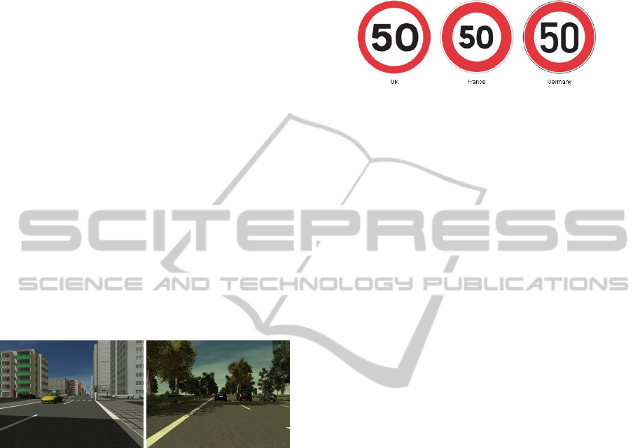
Figure 4: Different scenes created by the Environment Plug-
In. A rather rural and a rather urban atmosphere can be
achieved by adjusting parameters in the plug-in’s configu-
ration.
Using the right parameter sets, very different
scenes can be achieved, eg. urban scenes by turn-
ing guard rails off and street lights on, using short
distances between adjacent buildings and a close lat-
eral distance to the road bound, or rural scenes with
many trees, few buildings far from the road with large
distances, no street lights and guard rails turned on.
Since all objects are created and placed in a random
manner, scenes usually do not repeat. A rich scene is
a good source of disturbance for eg. object detection
methods that have to cope with large disturbances in
the real world.
5.3 Traffic Sign Plug-in
Traffic sign recognition is a relevant task executed by
some ADAS. Sign design differs between countries
(see Fig. 5), and variable message signs need to be
taken into account as well. Signs can have different
contrasts and reflectance properties.
Figure 5: Different countries use different traffic sign de-
sign. A detection method that has been trained on UK signs
might not recognize French or German signs appropriately.
The traffic sign plug-in creates traffic sign posts
and traffic sign gantries (with attached variable mes-
sage signs) randomly according to given frequencies.
In addition to integrating the objects to the scene, the
plug-in provides meta information about the sign the
vehicle is approaching or that has just been passed as
well as region of information (ROI) ground-truth for
all visible signs.
The set of used signs, properties of every sign (in-
cluding the location of the used texture file) as well
as the meta information provided for it can be config-
ured. Like that it is easy to use eg. only speed limit
signs for a test, or to set up a batch test (compare 2.4)
where different country specific sets of traffic signs
are used for otherwise identical scenes.
5.4 Random Test Plug-in
Testing a system usually involves its exposure to a va-
riety of different conditions. In the best case, a sys-
tem should be tested for all possible combinations of
conditions, or at least a sufficiently fine sampling of
the combinatorial space. It is obvious that with an in-
creasing number of dimensions, this turns out to be a
very hard task. Relevant conditions for an ADAS that
detects objects can be
• velocity of the vehicle,
• curvature of the road,
• illumination intensity,
• illumination direction (elevation and azimuth),
• lane marking contrast,
• visual density of the scene (amounts and positions
of scene objects).
ADAS have to be tested while driving many thou-
sands of kilometers in the real world. Testing con-
ditions are controlled by test protocols as much as
possible, so it is made sure that tests include differ-
ent weather conditions, different times of the day and
A VERSATILE SIMULATED REALITY FRAMEWORK - From Embedded Components to ADAS
183

so on, but there are many parameters that can not be
directly controlled, like for instance the structure of
surrounding traffic. So it is assumed that, given a
sufficient number of kilometres of testing, a largely
unknown parameter sub space is sampled sufficiently
well.
The Random Test Plug-In provides a means of
systematic random sampling of a configuration sub
space. A set of simulator parameters can be chosen.
These parameters are then varied according to given
rules. For some parameters it is not feasible to have
large jumps, e.g. natural illumination exhibits a cer-
tain continuity. The so-called Triangle Variator varies
a parameter within a given interval by first linearly in-
creasing the value from a given minimum to a given
maximum value and then decreasing it again to the
minimum. The time within that the change is happen-
ing is a random variable of which the user specifies
the limits. The Step Variator sets the value of a pa-
rameter constant for some time and then changes it to
another value drawn from a random variable. The in-
terval of the parameter’s value as well as the interval
of the dwell time can be chosen. Binary parameters
can be varied using the Toggle Variator.
Using different variation timings and the right lim-
its for the values, TrafficSimulation will stochastically
sample the given configuration space, which means
that the longer the simulation runs, the more thor-
oughly the sampling is.
5.5 Calibration Plug-in
This plug-in adds a calibration board (see 6) to the
scene. Position and orientation relative to the virtual
camera as well as size and the number of rectangles
can be specified. Calibration is needed for monitor
HIL tests (see 6.2).
Figure 6: In order to calibrate the camera, eg. in a monitor
HIL application.
5.6 Data Write Plug-in
This plug-in provides a simple means of writing a
subset of simulator variables to a spread sheet file. In
a configuration file, the set of used variables and the
according number of used decimals can be specified.
As for any module, the update time can be adjusted,
which corresponds to the sampling rate of the written
data. When the plug-in is active, it will add one row
to the spread sheet per update step. Writing to disk
is performed in a separate thread, so no I/O blocking
interferes with the simulation. The obtained file can
be opened by any spread sheet editor like EXCEL, or
with MATLAB.
5.7 CarSIM Plug-in
For many test scenarios, it is sufficient if the simu-
lated camera runs along the simulated road without
realistic pitch and roll motions affecting it. For other
test scenarios, a more realistic simulation is needed.
Since the focus of NISYS is not on designing vehi-
cle models, no advanced vehicle model is provided.
If a really sophisticated model is needed for testing,
eg. when a realistic breaking maneuver is part of the
test, TrafficSimulation can be complemented by the
state-of-the-art vehicle simulation software CarSIM.
The CarSIM plug-in requires a running version of
the CarSIM vehicle simulation software. The plug-
in communicates to the software by feeding steering
and acceleration commands as well as necessary in-
formation about the structure of the road (slopes and
friction coefficients for each wheel) to it, and read-
ing information about resulting vehicle position and
orientation.
5.8 External Driver Model Plug-in
For a large number of cases, ADAS react to given
driver behaviour by issuing warnings. For interven-
ing systems, the situation is different. An interven-
ing ADAS acts on the steering and/or on the accel-
erator/breaks. Such systems need particularly careful
testing, because their disfunctioning may cause seri-
ous accidents instead of avoiding them. Intervening
systems communicate with the power steering sys-
tem, throttle or brakes using the CAN Bus.
The External Driver Model Plug-In replaces the
simulated driver. Steering and/or acceleration com-
mands can be obtained from the CAN Bus Plug-In.
The plug-in is used in closed-loop scenarios (see 6.3).
PECCS 2012 - International Conference on Pervasive and Embedded Computing and Communication Systems
184

5.9 Steering Wheel Plug-in
TrafficSimulation can be used as a virtual reality driv-
ing simulation. This is useful, on the one hand, for
recording human driving behaviour in the situation
of cognitive experiments. On the other hand, it can
be used for testing if an ADAS actually detects the
driver’s mistakes and reacts appropriately to them.
In order to feed human driver’s input to the vehi-
cle, this plug-in replaces the simulated driver. Cur-
rently, the plug-in is available under Microsoft Win-
dows only: It uses the DirectX library for reading
from a USB gaming steering wheel. Because DirectX
establishes an intermediate layer between manufac-
turer and client software, any steering wheel can be
used.
5.10 Plot Plug-in
For many purposes it is helpful to monitor state vari-
ables in a graphical manner - deviations from ex-
pected behaviour, discontinuities, noise levels etc.
can be easily assessed by looking at a plot rather than
at figures in a spread sheet file (see Fig. 7). The Plot
Plug-In offers the possibility to monitor several state
variables on-line, zooming, showing multiple curves
in one plot. The sample rate can be defined by the
user as well as the buffer size.
Figure 7: Screen shots from plots in two different situa-
tion. The left plot shows the typical development of the
lateral position during a lane change. The right plot shows
the changes of the gier rate while entering a curve.
5.11 Multi Driver Plug-in
This plug-in allows to couple several instances of
TrafficSimulation using a special server program. All
instances share the same environment, and drivers
can see the other vehicles. A separate program, the
MultiSimulatorServer, connects to an arbitrary num-
ber of instances of TrafficSimulation (each running
on a separate computer). Using the network infras-
tructure (see 4.4), it requests vehicle state data from
every instance. All instances are started simultane-
ously using remote procedure calls. At a sufficient
frequency, all simulator instances send the requested
state data to the server. The server compiles data of
all instances to a large data package and broadcasts
it back to all instances. Data are received and inter-
preted by the Multi Driver Plug-In in order to cor-
rectly render the surrounding vehicles, keep the clock
synchronized with the server clock. The multi driver
system is extremely robust. It can cope with miss-
ing data packages using dead reckoning, and even a
disconnecting simulator instance does not affect the
stability of the system. It is used in a project for cog-
nitive experiments.
5.12 Head Tracking Plug-in
In order to improve the quality of the presented vi-
sual information and to enhance the immersion of
the subjects, the Head Tracking Plug-In provides a
means to align the virtual camera that is used to ren-
der the scene with the actual head position of the sub-
ject. Especially for situations where a very short dis-
tance between subject and screen is present, differ-
ences between assumed and actual head position lead
to inaccurate visual stimuli. Additionally, head move-
ments reveal to the subject that the screen plane sep-
arates real from virtual world due to the missing mo-
tion parallax. The Head Tracking Plug-In solves both
problems using a Nintendo WiiMote controller as the
tracking device (compare (Noth et al., 2010)).
6 EXAMPLE APPLICATIONS
NISYS TrafficSimulation has been and is currently
successfully used in industrial and academic projects.
We present here briefly some example applications.
6.1 Software-in-the-Loop (SIL)
During the development phase of software compo-
nents for ADAS, these components are tested us-
ing standard Hardware (PC). In conjunction with the
NISYS ADAF (Advanced Development and Analy-
sis Framework), software modules as well as entire
ADAS applications can be analyzed using simulated
data. In this scenario, the sensor data can be provided
directly to the software modules without using physi-
cal sensors (e.g. camera).
6.2 Monitor HIL
For the Hardware-In The-Loop scenario, a camera or
the entire embedded components (camera and embed-
ded processor) are placed in front a screen. In addi-
tion to the simulated scene, information available in
real vehicles via CAN bus can be provided by the
A VERSATILE SIMULATED REALITY FRAMEWORK - From Embedded Components to ADAS
185
simulator using the CAN Bus Plug-In (see 5.1). The
calibration of the camera can be facilitated using the
Calibration Plug-In (see 5.5).
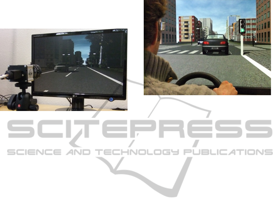
Figure 8: Monitor HIL. The picture shows a scene gener-
ated by the simulator under real time conditions. In this
scenario, the video data recorded by a CMOS Camera are
processed on a standard PC in order to detect lane mark-
ings and traffic signs. For analyzing the performance of the
detection modules, the ground truth data are also sent via
ethernet to the PC. A black box that shields the setup from
scattered light has been removed in order to take the photo.
See also the video on www.cstlab.net.
6.3 Closed Loop Scenario
For testing an intervening ADAS application, addi-
tionally to feeding sensor data into the system (com-
pare 6.2), the simulation needs to react to steering
and/or acceleration commands. TrafficSimulation can
realize this scenario using the External Driver Model
Plug-In (see 5.8), which feeds CAN Bus signals gen-
erated by the application to the vehicle model. This
way, lane keeping systems can be tested. If a sophis-
ticated vehicle model is needed, for instance when ro-
bustness of the different road surfaces shall be tested,
the CarSIM Plug-In (see 5.7) can add realism to the
test.
7 CONCLUSIONS AND
OUTLOOK
We presented a versatile simulated reality framework
allowing to develop, asses and benchmark embedded
components, entire ADAS, related network interac-
tions and models of human driving behaviour. The
simulated sensor input and the incorporation of mod-
els based on collected driving data from human sub-
jects, provide naturalistic stimuli and allow an easy
and fast transfer of all achieved results. The presented
simulator is a very robust and powerful tool that has
Figure 9: TrafficSimulation used for driving experiments.
In this tabletop simulator, a Logitech G27 steering wheel
is used as input device, and a 46” sony TV screen, which
provides 70 degree of visual field.
proven its usability in several industrial and academic
projects.
Important next steps, to further reduce the gap be-
tween simulation and reality, will be the incorporation
of pedestrians, the use of High Dynamic Rendering
(HDR) and to implement an optical models for simu-
lating camera options.
ACKNOWLEDGEMENTS
The authors acknowledge support from the German
Federal Ministry of Education and Research within
the National Network Computational Neuroscience –
Bernstein Fokus: “Learning behavioral models: From
human experiment to technical assistance”, grant
FKZ 01GQ0951.
REFERENCES
Gowal, S., Zhang, Y., and Martinoli, A. (2010). A realis-
tic simulator for the design and evaluation of intelli-
gent vehicles. In Intelligent Transportation Systems
(ITSC), 2010 13th International IEEE Conference on,
pages 1039—-1044. IEEE.
Lochert, C., Barthels, A., Cervantes, A., Mauve, M., and
Caliskan, M. (2005). Multiple simulator interlinking
environment for IVC. Proceedings of the 2nd ACM
international workshop on Vehicular ad hoc networks
- VANET ’05, Dll:87.
Noth, S., Schrowangen, E., and Iossifidis, I. (2010). Using
ego motion feedback to improve the immersion in vir-
tual reality environments. In ISR / ROBOTIK 2010,
Munich, Germany.
PECCS 2012 - International Conference on Pervasive and Embedded Computing and Communication Systems
186

Peh, C., Panerai, F., Droulez, J., Cornilleau-P
´
er
`
es, V.,
and Cheong, L. (2002). Absolute distance percep-
tion during in-depth head movement: calibrating optic
flow with extra-retinal information. Vision research,
42(16):1991–2003.
Schroth, C., D
¨
otzer, F., Kosch, T., Ostermaier, B., and
Strassberger, M. (2005). Simulating the traffic ef-
fects of vehicle-to-vehicle messaging systems. In Pro-
ceedings of the 5th International Conference on ITS
Telecommunications, page 4. Citeseer.
Yang, Q. and Koutsopoulos, H. (1996). A Microscopic
Traffic Simulator For Evaluation of Dynamic Traffic
Management Systems. Transportation Research Part
C: Emerging Technologies, 4(3):113–129.
A VERSATILE SIMULATED REALITY FRAMEWORK - From Embedded Components to ADAS
187
