TraxBot
Assembling and Programming of a Mobile Robotic Platform
André Araújo
1
, David Portugal
1
, Micael S. Couceiro
1
, Carlos M. Figueiredo
2
and Rui P. Rocha
1
1
Institute of Systems and Robotics (ISR),University of Coimbra (FCTUC), Coimbra, Portugal
2
RoboCorp, Department of Electrical Engineering (DEE), Engineering Institute of Coimbra (ISEC), Coimbra, Portugal
Keywords: Mobile robot, Embedded system, Design, Assembling and testing.
Abstract: This work presents the TraxBot mobile robot design, a ground platform recently developed for applications
in the mobile robotics field. The assembling of the robotic system, with description of its components as
well as information about the microcontroller programming, development and testing are presented. The
TraxBot is a multidisciplinary platform and is ideal for education, since it is easily programmed with open-
source tools requiring basic knowledge of other areas beyond robotics, like mechanics, control or energy
management. Although being released in a stable version, the robot is continually in development, with the
ability to incorporate extensions to its design and new features.
1 INTRODUCTION
In recent years, a great deal of research on mobile
robotics has been noticed. Several different robotic
systems have emerged in order to assist or replace
human operators mostly in tiring, repeating or time-
consuming tasks. Earlier, the focus of research was
especially on large and medium structures. Howev-
er, with the advancement in sensor miniaturizations
and the increasing in the speed and capability of
microcontrollers in the past years, the emphasis
shifted to the development of smaller, lower cost
robots and experimentation with groups of robots.
In this paper, we present the design and imple-
mentation of a portable ground robot developed in
the Mobile Robotics Laboratory (MRL) at the Insti-
tute of Systems and Robotics (ISR) in the University
of Coimbra. The TraxBot is an ideal platform for
education, since it can provide students with basics
required to develop autonomous mobile robots, both
at the hardware level (mechanics, energy, locomo-
tion, embedded electronics, sensors) and software
level (control theory, microcontroller programming,
trajectory planning, localization). The setting up,
development and programming of this robot was
motivated by experimentation and research in coop-
erative multi-robot systems, more specifically teams
of robots with distributed control to perform cooper-
ative patrolling (Portugal and Rocha, 2010) and
swarm foraging (Couceiro et al., 2011) tasks.
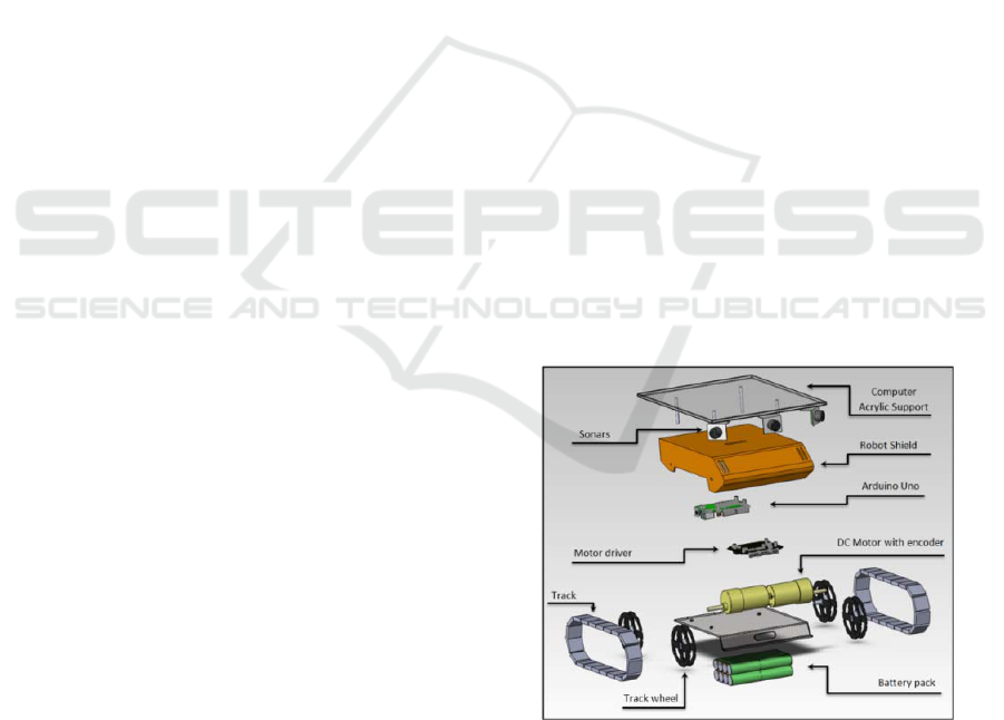
Figure 1: Mechanical structure of the TraxBot.
2 HARDWARE SPECIFICATION
The robotic platform in focus is a differential drive
system built upon the Traxster II Robot educational
Kit (Traxster II, 2008), equipped with 2 DC gear-
head motors with quadrature wheel encoders. Rub-
ber bands were attached to the original tracks to
increase friction and reduce slip during locomotion.
The processing unit consists of an Arduino Uno
board (Arduino Uno, 2010) equipped with a micro-
controller ATmega 328p from Atmel, which controls
the platform’s motion through the use of the Bot’n
Roll OMNI-3MD board (Bot’n roll, 2011).
301
Araújo A., Portugal D., S. Couceiro M., M. Figueiredo C. and P. Rocha R..
TraxBot - Assembling and Programming of a Mobile Robotic Platform.
DOI: 10.5220/0003713303010304
In Proceedings of the 4th International Conference on Agents and Artificial Intelligence (ICAART-2012), pages 301-304
ISBN: 978-989-8425-96-6
Copyright
c
2012 SCITEPRESS (Science and Technology Publications, Lda.)
For range sensing, the robot uses Maxbotix So-
nars MB1300 with a maximum range of approx-
imately 6 meters (Maxbotix, 2005), which can have
a configurable disposition and the possibility of
employing up to 4 sonars in one platform using the
analog ports of the Arduino Uno board.
Additionally, to enable point-to-point communi-
cation, the Xbee Shield, consisting on a ZigBee
communication antenna attached on top of the Ar-
duino Uno board was also incorporated.
As for power source, two packs of 12V
2300mAh Ni-MH batteries are deployed under the
chassis of each robot to ensure good autonomy.
Finally, the platform has the ability to include a
10” netbook on top of an acrylic support, extending
the processing power and providing more flexibility.
The netbook has the advantage of enabling commu-
nication via WiFi 802.11 b/g/n. In Figure 1, a 3D
general view of the TraxBot assembly is presented.
Some hardware specifications are presented in
Table 1. The choice of the robot design was made
essentially due to the following reasons:
• Robustness: All hardware is either aluminum or
stainless steel;
• Low Cost: The platform costs around 300€ (not
considering the netbook);
• Operability: It has the ability to maneuver in
many different types of terrain and surface topo-
graphies;
• Dimension: It is adequate for both indoor and
outdoor experiments;
• Autonomy: It can operate continuously around 2-
3 hours.
• Flexibility: It can incorporate many new exten-
sions and components (e.g., LEDs, cameras, LI-
DARs, grippers, etc.).
• Hybrid design: It is able to work with and with-
out a small netbook on top of the platform ac-
cording to the user’s desire and applications.
Table 1: TraxBot Hardware Specifications.
Voltage Range [V] 9-14
Electric Current in Operation [mA] 1200
Electric Current in Standby [mA] 110
Maximum Speed [m/s] 0,95
Weight [g] 2045
Weight with netbook [g] 3160
Width [mm] 203
Length [mm] 229
Height [mm] with sonars 110
Height [mm] with netbook 155
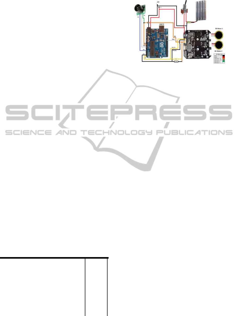
Figure 2: Main Electronic Circuit.
3 DEVELOPMENT
An outline of the electronics of the TraxBot platform
is presented in Figure 2. The Arduino Uno board, the
Bot’n Roll OMNI-3MD driver and the DC motors
are located inside the robot shield, while the Maxbo-
tix MB1300 sonar range finders are placed on top of
the chassis. The battery packs are under the chassis
and the circuit switch is located in the shield’s rear.
The batteries provide the energy source to the en-
tire system. Having the Arduino Uno board as the
central component of the system, a sonar range find-
er connects to it through the A0 port, receiving ana-
log inputs from the sonar and reading voltage values.
As for the connection to the Bot’n Roll motor driver,
the ports A4 and A5 are used for Serial Data and
Serial Clock Connection respectively.
The other three ports (A1-A3) of the Arduino
Uno are available for integration of more sensors.
The USB jack on the microcontroller connects to the
netbook and is used to receive (RX) and transmit
(TX) TTL serial data, which is decoded using a
USB-to-TTL Serial chip in the microcontroller.
The motor driver is connected to the two DC
Gearhead Motors through the encoder connectors.
The Bot’n Roll OMNI-3MD motor driver has the
ability to control three motors in omnidirectional
platforms by sending linear velocity, direction and
speed commands, performing both velocity and
position control. Furthermore, it has the flexibility to
reset the parameters of PID control, reading encod-
ers, measuring the battery voltage and monitoring
the temperature of the board. The robot incorporates
two DC motors with 624 pulses per output shaft
revolution. Encoder information is read by the motor
drive and provided to the Arduino Uno.
The Arduino Uno is an open-source hardware
board based on the ATmega328 microcontroller,
which provides serial communication. Its CPU runs
at 16 MHz and provides 14 MIPS of peak processing
ICAART 2012 - International Conference on Agents and Artificial Intelligence
302
1
A stable version of the Arduino code used to program the
TraxBot and videos of all experiments are available at:
http://paloma.isr.uc.pt/~aaraujo/TraxBot/
power. An ATmega8U2 on the board channels the
serial communication over USB and appears as a
virtual COM port to software on the computer.
The open source Arduino environment is a po-
werful tool for education, in specific, microcontrol-
ler programming. In the current implementation, the
robot has the ability to perform navigation com-
mands, plan paths from an origin to a destination,
perform self-localization based on its odometry and
avoid obstacles in a reactive way using the sonars.
4 EXPERIMENTS
In order to evaluate the proposed platform, several
tests were conducted on a lab scenario composed by
a green and plain carpet with no flaws with a top
mounted camera which recorded the experiments
1
.
4.1 Odometry
The TraxBot was placed in the carpet with the objec-
tive to perform a square trajectory with one-meter of
side length, in both clockwise (CW) and counter-
clockwise (CCW) directions. This test is done to test
its odometry, being extremely challenging due to the
fact that the robot always turns in the same direction,
and tending to accumulate dead reckoning errors
without compensation in the opposite direction.
Figure 3 illustrates the scenario and trajectories
performed by the platform during the experiments.
The trajectories illustrated were collected using an
overhead camera mounted on top of the scenario.
a) b)
Figure 3: a) Odometry square test in CCW direction. b)
Odometry square test in CW direction.
The tests were performed relying on the odome-
try system of the robot and without the assistance of
any sensor or exterior localization information. As it
is depicted in Figures 3.a) and 3.b), the robot per-
forms movements in straight line with high accura-
cy, however finds it difficult to rotate exactly 90° as
expected, with the error varying in different turns.
Besides, it is noticeable that, as it rotates around
a fixed point, a minor slipping effect is present.
Nevertheless, the accumulated error in the end of
each test, after one lap, is reduced. The trial in CCW
direction ends with a positional difference of 9.67cm
and an angle difference of -4.93° to the robot’s ini-
tial pose; while in the CW direction the positional
error is 7.71 cm and the angle difference is +2.13°.
4.2 Sensing Accuracy
In this test, a calibration phase was conducted to
convert the analog output values given by the sonar
readings to centimeters. By measuring sonar read-
ings in a straight line at a distance to a wall between
5 to 200 cm, with an increment of 5 cm; a curve
fitting power function f(x)= a·x
b
+c converted the
analog values data to centimeters.
In order to test the robustness of the calibration
function and the sensing equipment, a simple test
was conducted. As shown in Figure 4.a), the robot
was placed two meters away from a regular obstacle
and was driven in a straight line in its direction with
a constant velocity of 0.14m/s. The robot stopped
when it was 3 cm away from the obstacle. The sonar
data was saved during the experiment.
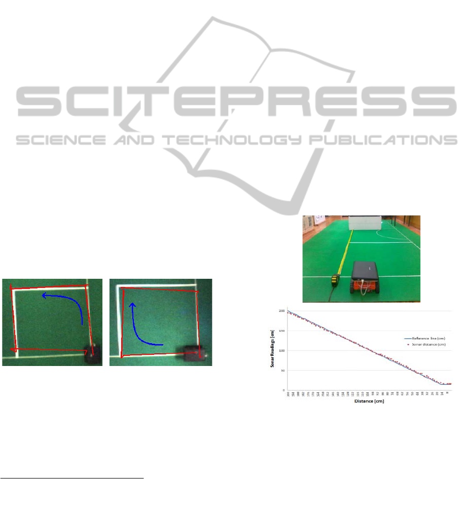
a)
b)
Figure 4: a) Experimental scenario. b) Range testing re-
sults.
As seen in Figure 4.b), sonar readings are very
close to the line of reference and can be used relia-
bly to assist the robot’s navigation. The average
sonar measuring error was 1.83 cm, while the max-
imum error was 5 cm. These few observable errors
have diverse sources, such as the limits imposed by
TraxBot - Assembling and Programming of a Mobile Robotic Platform
303

the sonar resolution, approximation errors caused by
the calibration function, the manual measurement of
2 meters used in the experiment, and even the small
errors that accumulate when the robot diverts while
moving in a straight line.
4.3 Obstacle Avoidance
In the final test, an obstacle was added to the scena-
rio. Programmed to navigate in a straight line from
an initial configuration into an obstacle, the robot
reactively avoids it using three sonars mounted be-
low the acrylic support. After overcoming the ob-
stacle, the robot replans its trajectory and drives to a
final position. Figure 5 presents the trajectory of the
robot during the experiment.
Figure 5: Overview of the reactive obstacle avoidance test.
The red line denotes the robot trajectory in the experiment.
This test demonstrates that the robot is able to
avoid obstacles and navigate safely in the environ-
ment. It decides in which direction it should rotate,
while avoiding an obstacle through the composed
readings of the three sonars. Note that some posi-
tional errors still propagate during the test due to its
odometry system. Nevertheless, the robot is able to
drive itself autonomously.
5 CONCLUSIONS
This paper presents the development and experimen-
tal evaluation of a robotic platform named TraxBot.
The TraxBot is suitable for enhancing basic pro-
gramming skills, for exploring algorithms of interest
to the robotics community and will also be useful in
the fields of multi robot systems, since it is a cost-
efficient, off-the-shelf solution. Furthermore, it takes
advantage of the addition of computing power that a
laptop can offer, since it allows the capability to
extend its processing unit. Hence, the TraxBot offers
both a realization of a practical autonomous robot
and a novel resource that can be leveraged toward
educational and research goals.
In the near future, the ZigBee module will be
used to develop point-to-point communication with
a team of TraxBots in cooperative multi-robot tasks.
Moreover, in order to strengthen the robot’s naviga-
tion, we intend to use the overhead cameras on our
lab scenario for tracking and correcting robot’s posi-
tions eventually with the assistance of RGB LEDs
deployed on top of the robot. Finally, we intend to
release a TraxBot driver for ROS (Quigley et al.,
2009), a popular robotic integration framework used
in research laboratories and industry worldwide.
ACKNOWLEDGEMENTS
This work was supported by PhD scholarships
(
SFRH/BD/64426/2009) and (SFRH/BD/73382/2010) by
the Portuguese Foundation for Science and Technol-
ogy (FCT), the Institute of Systems and Robotics
(ISR) and RoboCorp at the Engineering Institute of
Coimbra (ISEC) also under regular funding by FCT.
The authors gratefully acknowledge Soluções de
Automação e Robótica (SAR) for their contribution
and feedback.
REFERENCES
Arduino Uno, 2010: Available at: http://arduino.cc/
en/Main/ArduinoBoardUno. Retrieved on 18
th
October
2011.
Bot’n roll, 2011: Manual OMNI-3MD. Available at: http://
botnroll.com/omni3md/downloads/Manual%20OMINI
3-MD(18-07-2011).pdf. Retrieved on 18
th
October
2011.
Couceiro, M., Ferreira, N., Rocha, R., 2011: Multi-Robot
Exploration based on Swarm Optimization Algo-
rithms. In ENOC’2011: Proc. of the 7th European
Nonlinear Dynamics Conf. Rome, Italy, 24-29 July.
Maxbotix, 2005: MB1300 XL-MaxSonar®-AE0™ Data-
sheet. Available at: http://www.maxbotix.com/docum
ents/MB1200-MB1300_Datasheet.pdf. Retrieved on
18
th
October 2011.
Portugal, D., Rocha, R., 2010. MSP Algorithm: Multi-
Robot Patrolling based on Territory Allocation using
Balanced Graph Partitioning. In SAC 2010: Proc. of
25th ACM Symposium on Applied Computing. Sierre,
Switzerland, March 22-26, pp. 1271-1276.
Quigley, M., Gerkey, B., Conley, K., Faust, J., Foote, T.,
Leibs, J., Berger, E., Wheeler, R. and Ng, A., 2009:
ROS: an open-source Robot Operating System. In
ICRA’2009 Workshop on Open Source Software.
Traxster II, 2008: Traxster
TM
II Assembly Manual, Version
1.0. Available at: http://www.roboticsconnection.
com/multimedia/docs/TraxsterAssemblyGuide.pdf.
Retrieved on 18
th
October 2011.
ICAART 2012 - International Conference on Agents and Artificial Intelligence
304
