
FAST TEMPLATE MATCHING FOR UMTS CODE KEYS
WITH GRAPHICS HARDWARE
Mario Vigliar, Giancarlo Raiconi
DMI, Universit
`
a degli Studi di Salerno, via Ponte don Melillo, 84083, Fisciano SA, Italy
Alan David Sanders
Wider Networks, 881 Ponce de Leon Ave Suite 10, 30306 Atlanta GA, U.S.A.
Keywords:
Measurements on 3G networks, GPU computation, FFT.
Abstract:
Template matching is a milestone application in Digital Signal Processing, and sets its roots in fundamental
numeric filtering theory, as well as in time and frequency domain analysis. Radio signals, with mass spreading
of high bandwidth cellular networks, have become in recent years much more critical to handle in terms of
QoS (Quality of Service), QoE (Quality of Experience) and SLA (Service Level Agreement), putting mobile
carriers in the need to monitor their network status in a more detailed and efficient way than in past. Here
an efficient use case of GPU computing applied to fast signal processing will be illustrated, with particular
interest in study and development of a SIMD Linear and FFT-based cross correlation of multiple code keys in
air-captured streams for UMTS networks. Developed techniques have been used with success in a commercial
available 3G geotagged scanning equipment.
1 INTRODUCTION
The aim of this paper is to present a parallel comput-
ing approach to solve the problem of precisely mea-
sure the maximal exposure to UMTS (Universal Mo-
bile Telecommunications System) signals in an area.
Because the particular nature of this signal character-
ized by a high crest factor such task cannot be sim-
ply carried out by a field intensity meter but the only
means consists in really receive the signal by an ap-
propriate receiver and evaluate the signal quality.
Traditionally to this purpose, which is a computa-
tionally intensive task, the receiver was mounted on a
vehicle, the received signal was recorded and used to
signal exposition evaluation carried out offline. Such
approach result on a set of costly operations in terms
of time spent and specialized components used. Our
approach consist of direct computation of necessary
data directly onboard using a standard laptop, costly
signal processing operation are performed efficiently
exploiting the power of a standard GPU of the laptop
using NVidia’s CUDA framework.
The paper is organized as follows. In the next sec-
tion the problem is stated by as template matching
problem, solvable using classical Digital Signal Pro-
cessing (DSP) technique in order to compute the cross
correlation between sequences. the third section is
devoted to describe the computational technique im-
plemented in the Wider Network’s scanner based on
a specialized FFT algorithm running on GPU. In the
following section the computational aspects of the al-
gorithm are studied in detail and results of benchmark
are reported.
Finally there is a concluding section.
2 PROBLEM STATEMENT
In this section we recall briefly relevant features of the
UMTS signal and describe what computational tasks
need to perform in order to assess the quality of the
signal itself.
2.1 A Brief Sketch of the UMTS Signal
To understand the algorithm which is used to evaluate
UMTS signal quality the knowledge of some details
of its characterization are necessary. UMTS uses a
multiple access technique, where several users as well
as the signalization is separated by different spreading
265
Vigliar M., Raiconi G. and David Sanders A..
FAST TEMPLATE MATCHING FOR UMTS CODE KEYS WITH GRAPHICS HARDWARE.
DOI: 10.5220/0003362902650272
In Proceedings of the 1st International Conference on Pervasive and Embedded Computing and Communication Systems (PECCS-2011), pages
265-272
ISBN: 978-989-8425-48-5
Copyright
c
2011 SCITEPRESS (Science and Technology Publications, Lda.)
codes (WCDMA - Wideband Code Division Multiple
Access). By multiplication with the spreading code,
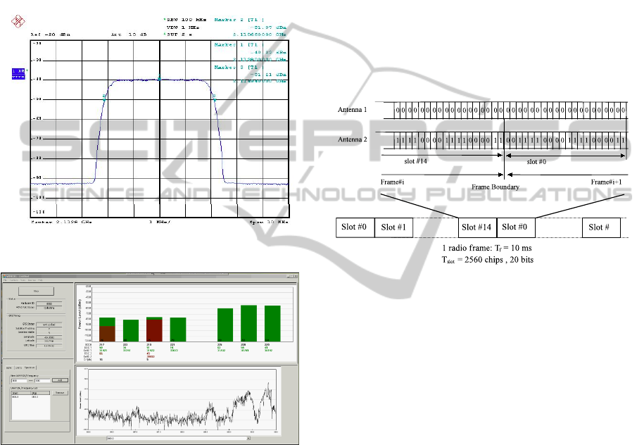
the data signal is spread in the spectrum. Fig. 1a
taken from (Bornkessel and Wuschek, 2006) shows
a real measured UMTS signal in frequency domain.
The 10 dB bandwidth is about 4.3 MHz. UMTS sig-
nals are noise like showing a large difference between
short time maxima U
Peak
and the RMS value U
RMS
(crest factor C = 20 · log(U
Peak
/U
RMS
) in the 8 to 10
dB range, variable with the traffic of the station).
(a)
(b)
Figure 1: UMTS signal spectrum and its analysis with
WIND3G.
In order to determine the maximal exposure in
a defined volume, the sweeping method is recom-
mended, due to signal nature. Common Pilot Channel
(CPICH) is a fixed rate (30 kbps, Spreading Factor
- SF=256) downlink physical channel that carries a
pre-defined bit sequence. Figure 2 shows the frame
structure of the CPICH. The Primary CPICH is
used by the UEs (user equipments) to first complete
identification of the Primary Scrambling Code used
for scrambling Primary Common Control Physical
Channel (P-CCPCH) transmissions from the Node
B (in UMTS is the Base Transceiver Station). Later
CPICH channels provide allow phase and power
estimations to be made, as well as aiding discovery
of other radio paths. There is one primary CPICH (P-
CPICH), which is transmitted using spreading code 0
with a spreading factor of 256, notationally written as
C
ch,256,0
. Optionally a Node B may broadcast one or
more secondary common pilot channels (S-CPICH),
which use 256 codes arbitrarily chosen, written as
C
ch,256,n
where 0 < n < 256. The CPICH contains
20 bits of data, which are either all zeros, or in the
case that Space-Time Transmit Diversity (STTD)
is employed, is a pattern of alternating 1’s and 0’s
for transmissions on the Node B’s second antenna.
The first antenna of a base station always transmits
all zeros for CPICH. See below for P-CPICH and
S-CPICH characterization.
k
Figure 2: Frame structure and modulation pattern for
Common Pilot Channel.
In case transmit diversity is used on P-CCPCH
and SCH, the CPICH shall be transmitted from both
antennas using the same channelization and scram-
bling code. In this case, the pre-defined bit sequence
of the CPICH is different for Antenna 1 and Antenna
2, see figure 2 (top section). In case of no transmit
diversity, only the bit sequence of Antenna 1 is used.
The channelization codes are the same codes as
used in the up-link, namely Orthogonal Variable
Spreading Factor (OVSF) codes that preserve the or-
thogonality between downlink channels of different
rates and spreading factors. The channelization code
for the Primary CPICH is fixed to C
ch,256,0
as previ-
ously stated, and the channelization code for the Pri-
mary CCPCH is fixed to C
ch,256,1
. In each cell the UE
may be configured simultaneously with at most two
scrambling codes. The scrambling code sequences
are constructed by combining two real sequences into
a complex sequence. Each of the two real sequences
are constructed as the position wise modulo 2 sum of
38400 chip segments of two binary m-sequences gen-
erated by means of two generator polynomials of de-
gree 18. The resulting sequences thus constitute seg-
ments of a set of Gold sequences.
The scrambling codes are repeated for every 10
PECCS 2011 - International Conference on Pervasive and Embedded Computing and Communication Systems
266

ms radio frame. Let x and y be the two sequences
respectively. The x sequence is constructed using the
primitive (over GF(2)) polynomial 1+X
7
+X
18
. The
y sequence is constructed using the polynomial 1 +
X
5
+ X
7
+ X
10
+ X
18
.
2.2 Monitoring and Mapping UMTS
Signal Quality
Our main interest is in “measurement for perfor-
mances” and so our main aim will be to decode air-
captured data to evaluate if it is possible to decode
some subsequences in useful cell broadcasting pack-
ets. As signal matching measure was used cross cor-
relation:
( f ? g)[n]
def
=
∞
∑
m=−∞
f
∗
[m] g[n +m]. (1)
for a fixed n, in the interval [0...n] it is possible to
compute the single terms of sum sequence just iterat-
ing the product between f
∗
and g terms. For each iter-
ation, a single correlation value will be obtained, and
finding a local maxima will indicate the best match
position in the search reference of the candidate se-
quence. This computing method is often referred
as linear cross-correlation index, and used in online
systems when seeking for short length templates in
streaming references, due to overall small memory
footprint and good independency from floating point
precision on the target architecture. Linear cross-corr.
in fact, relies only on sum and multiply operations,
thus ensuring very good computing performances on
DSP-like systems, where MADD (Multiply and AD-
Dition) primitives are present in hardware, and often
within vectorial structures.
Let x,y two sequences and X, Y their Fourier
transforms it can be shown that:
F
−1
{
X
∗
· Y
}
n
=
N−1
∑
l=0
x
∗
l
·(y
N
)
n+l
def
= (x ? y
N
)
n
, (2)
which is the cross correlation of the x sequence
with a periodically extended y sequence defined by:
(y
N
)
n
def
=
∞
∑
p=−∞
y
(n−pN)
. (3)
This formulation is often referred as circular correla-
tion. Efficient implementations of Fourier transform
on PoT-length (Power of Two) sequences, like FFT
in its many flavors, offer us the chance to lower the
O(n
2
) complexity bound of linear correlation, to im-
prove performances in terms of no. of possible tem-
plates checkable for time unit (samples/secs).
3 WIDER NETWORKS CASE
STUDY
Wider Networks’ UMTS scanner (WIND3G - Figure
1b) has an CPICH Ec/Io
1
detection of -25 dB. Lower
Ec/Io detection comes from increased signal process-
ing power.
Given a fixed number of CPICH chips as tem-
plates, the lower is the requested Ec/Io ratio (to avoid
misdetections) the more processing power is needed.
Samples’ length is another key point when evaluating
the real computational complexity of the process, as
linear correlation needs to evaluate the signal fitness
on the whole target sequence. See Figure 3 to better
understand the detection thresholds in the seek pro-
cess.
We are aimed to improve timing for full cross
correlation between air-captured streams and a given
number of filters (512 scrambling codes for first
stage), starting from a vectorized version of lin-
ear cross correlation (provided in Intel Performance
Primitives libraries). Actual routines were running
in SSE2 cores, floating point single precision IEEE-
754 32 bits, and were multicore aware. There are
512 CPICH scrambling code sequences in UMTS.
WIND3G takes about 3580 chips worth of each and
correlates against one complete UMTS frame, which
is 38400 chips to find where these CPICHs have
peaks. This step is called “Searching code”, and it
is actually target of these performance benchmarks.
After searching the peak, a DSP algorithm called
Tracker takes it in charge to monitor variations over
time. Theoretical compound performances of the
Searcher+Tracker modules have a bottom limit of
25.5 dB. A peak with this magnitude (and lower) has
a considerable probability of being a false detection.
Wider Networks’ system are designed to work
in mobile environments (cars, service vans) as the
UMTS scanner is bundled with a GPS receiver and
a geotagging application, to write down on updated
maps the dB values, signal efficiency and other mea-
surements done when roaming across cell network
covered area. For this reason, their main comput-
ing unit is often a notebook, and so with no particular
and/or optimized processor for signal processing (up
to 2 cores, no SMP, no expansion slots for accelera-
tors, frequencies up to 2.5 GHz due to thermal and
power issues).
To overcome to these performance limits, a fast
circular cross correlator has been designed to run in
GPU, and most notably on NVidia GeForce 8xxx
1
In UMTS/CDMA Ec/Io refers to the portion of the RF
signal which is usable. It’s the difference between the signal
strength and the noise floor.
FAST TEMPLATE MATCHING FOR UMTS CODE KEYS WITH GRAPHICS HARDWARE
267
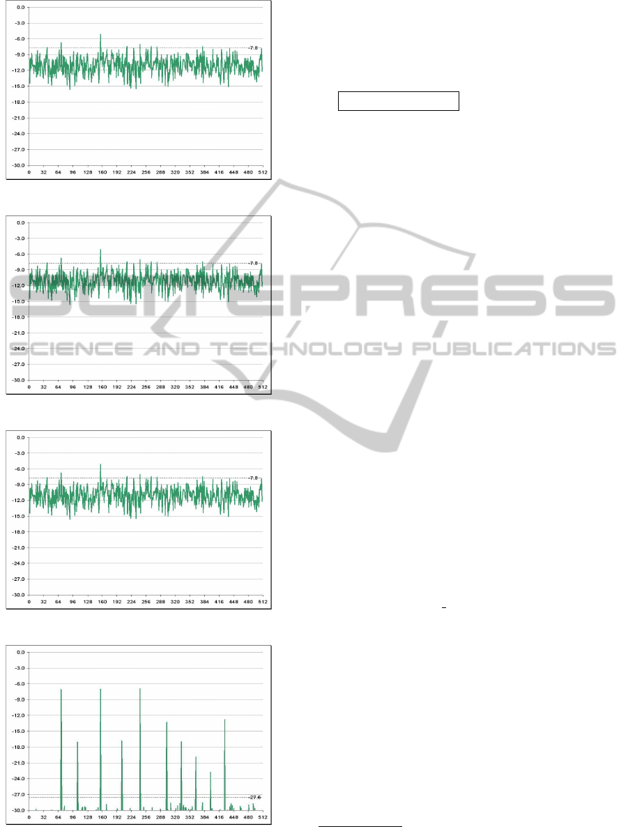
(a) -7.9 dB.
(b) -16.6 dB.
(c) -23.0 dB.
(d) -27.6 dB.
Figure 3: CPICH Ec/Io detection thresholds.
chipsets and newer, by using CUDA development
framework under Windows XP (both 32 and 64 bits).
The OS choice was mandatory to minimize porting
efforts of the whole WIND3G application, already
available for that system.
UMTS Cell Search
• Cell Search by correlating CPICH associated with
all 512 scrambling codes (α-search)
• In fast-mode (β-search) specified top few candi-
dates (sample positions) are correlated
1. Find the maximum correlation value for each
scrambling code → 512 max values (run code
in 1)
2. Sort these 512 max values, pick the top k scr.
codes (because the maximums of the rest scr.
codes will be anyway discarded later)
3. For each of these k scr-codes, sort their corre-
lation values for all positions disregarding the
values within +/-2 chips of a local max, and
pick the top j or so positions → In total, this
will give us k ∗ j initial candidates
4. Sort the k ∗ j candidates to find the final m can-
didates to β-search.
Running system use this setup: k = 200, j =
10, m = 200. Values have been tested on field and
provide satisfactory results for detection.
3.1 Circular Cross Correlation with
CUDA
Once tested the IPP
2
cross correlation code, strictly
optimized for x86 platforms, an offloaded routine
moving part of the computing costs in GPU is pro-
posed here. See Listing 1 for a significant snippet
from cudaCrossCorr 32fc.
Listing above requires some explanations for
some critical and interesting points. Firstly, this
CUDA code is totally “masked” (with singular excep-
tion at line 21), keeping reading and maintenance as
easy as for plain C/C++ source code. Thanks to mod-
ular CUFFT structure derived from FFTW library it
has been possible in fact to remove any direct kernel
invocation and substitute 1:1 the IPP calls in this al-
gorithm.
Remarkable point is moreover the stateful nature
of cross corr. code. A major drawback of circular
correlation vs. linear one, especially if built up to have
exactly the same external interface, would have been
2
Intel
R
Integrated Performance Primitives - see
http://software.intel.com/en-us/articles/intel-ipp/ for further
information.
PECCS 2011 - International Conference on Pervasive and Embedded Computing and Communication Systems
268

Listing 1: cudaCrossCorr 32fc source.
Listing 1: cudaCrossCorr 32fc source.
extern "C" void
cu daC ros sCo rr_ 32f c ( Co mp le x * h_ fi lt er _k er ne l ,
int fil te rS i ze , \
Co mp le x * h_s i gn al , int si gn al S iz e , \
Co mp le x * h_ co r r _ s i g n a l , int c or rSi ze , \
int lowLa g , bool si gn FF T e d )
{
// Pad signal and filter kernel
Co mp le x * h_ pa dd ed _s ig na l , h _ pa d de d _f i lt e r_ k er n e l ;
[. . .]
// Transform signal and kernel
if (! s i g n FF Te d ) {
cu f f t Ex e c C 2C ( plan , ( c u ff t C o mp l e x *) d_ s ig nal , \
( c uf f tC om p le x *) d _s i gn al , C UF F T _ FO R W A RD ) ;
}
cu f f t Ex e c C 2C ( plan , ( c u ff t C o mp l e x *) d _ f i l t e r_ ke rn el , \
( c uf f tC om p le x *) d_ fi lt er _k er ne l , C U F F T_ F O R WA R D ) ;
// Multiply coefficients together as in corr a.
*
conj(b)
Co m p l ex C on j P o i n t wi s eM u l A nd S ca l e < < < 3 2 , 256 > > > \
( d_ sig na l , d _ f i l t e r _k er ne l , ne w _s ize , 1. 0 f / ne w_ si ze
);
// Check if kernel execution generated and error
CU T _ C HE C K_ E R R OR \
(" Ke rn el f ai le d [ C o m p l e x Po i nt w is e Mu l An d S c a l e ] " );
// Transform signal back
cu f f t Ex e c C 2C ( plan , ( c u ff t C o mp l e x *) d_ s ig nal , \
( c uf f tC om p le x *) d _s i gn al , C UF F T _ IN V E R SE ) ;
[. . .]
}
been the re-computation of reference signal FFT. At
every cycle, in fact, a new chunk of ref. signal and
a new scrambling code would have been pushed to
the cudaCrossCorr function, that would have done the
FFT twice per iteration and then apply convolution
theorem, multiplying the resulting vectors and anti-
transform the result. Designed to work on multiple
cross correlations per session sharing the reference
signal, instead, using static variables to keep track of
how many FFT have been computed, on which part
of incoming signal and most important where results
are stored in memory, cudaCrossCorr can save up to
30% computing power (1 out of 3 FFT-based opera-
tions) per cycle, with a great advantage in terms of
execution time. See details in Listing 1 to see how
this simple mechanism works.
The only non-masked operation in cudaCrossCorr
body is the recombination of spectra after FFT execu-
tion, ( f
∗
∗ g) in eq. 1.
3.2 About Precision in
Cross-correlation
Several numeric tests have been executed, using
MATLAB as golden standard with its xcorr function
that implements circular cross correlation, computed
in double precision IEEE-754, complex arguments.
CUDA Version showed overall good perfor-
mances when compared to reference standard. See
Figure 4. CUDA FFT crossCorr, matched against
MATLAB FFT xcorr shows a residual term in the
order of ±5.0 · 10
−6
, so perfectly in line with expec-
tations for single precision 32 bit arithmetic of G92
cores.
ippsCrossCorr32fc on the other hand shows al-
most the same performance (single precision) on the
whole signal length, not visible for bigger Y scale,
with a notable exception on master signal’s tail. When
overlap between reference and template signal ex-
ceeded former’s length, cross correlation index starts
dropping towards zero, for effect of zero padding in-
side the matching function. Even if this behavior
has no practice relevance when looking for “best”
match (cross correlation index is guaranteed to be-
come lower than in other parts of data), it could have
dangerous effects if resulting vector will be normal-
ized against its L1 or L2 norm. These manipulations
are quite frequent in digital signal processing, and in
this case such these results could imply a loss of pre-
cision of successive steps of computation.
4 COMPUTATIONAL
CONSIDERATIONS
AND BENCHMARKS
As previously shown in CrossCorr code analysis, all
FFT computations have been offloaded from CPU
to GPU, and in first instance this process was flaw-
less and simple thanks to the CUFFT library usage.
CUFFT provides a simple interface for computing
parallel FFTs on an NVIDIA GPU, which allows
users to leverage the floating point power and paral-
lelism of the GPU without having to develop a cus-
tom, GPU based FFT implementation. FFT libraries
typically vary in terms of supported transform sizes
and data types. CUFFT API is modeled after FFTW
(see http://www.fftw.org), which is one of the most
popular and efficient CPU based FFT libraries.
Sadly, CUFFT implementation, or at least un-
til v2.1 of CUDA Toolkit, even showing a general
speedup against the underlying CPU structure (> 40
GFlop/s for a grand total of > 20 GB/s on GeForce
G92 8800GTS 512), doesn’t exploited the full poten-
tial of NV’s hardware computing power. That library
is in fact a collection of 5 different implementations
of part of Cooley-Turkey structure, often referred as
Radix2 FFT Scheme as in (Tian et al., 2004), extend-
ing it to cardinality of 3,4 and 5 elements per block,
thus adding to their library the capability to use also
Radix-3, Radix-4 and Radix-5 schemes.
Well accepted theory of “Mixed radix FFT
schemes” is described in detail in (Stasinski and
the re-computation of reference signal FFT. At ev-
ery cycle, in fact, a new chunk of ref. signal and
a new scrambling code would have been pushed to
the cudaCrossCorr function, that would have done the
FFT twice per iteration and then apply convolution
theorem, multiplying the resulting vectors and anti-
transform the result. Designed to work on multiple
cross correlations per session sharing the reference
signal, instead, using static variables to keep track of
how many FFT have been computed, on which part
of incoming signal and most important where results
are stored in memory, cudaCrossCorr can save up to
30% computing power (1 out of 3 FFT-based opera-
tions) per cycle, with a great advantage in terms of
execution time. See details in Listing 1 to see how
this simple mechanism works.
The only non-masked operation in cudaCrossCorr
body is the recombination of spectra after FFT execu-
tion, ( f
∗
∗ g) in eq. 1.
3.2 About Precision in
Cross-correlation
Several numeric tests have been executed, using
MATLAB as golden standard with its xcorr function
that implements circular cross correlation, computed
in double precision IEEE-754, complex arguments.
CUDA Version showed overall good perfor-
mances when compared to reference standard. See
Figure 4. CUDA FFT crossCorr, matched against
MATLAB FFT xcorr shows a residual term in the
order of ±5.0 · 10
−6
, so perfectly in line with expec-
tations for single precision 32 bit arithmetic of G92
cores.
ippsCrossCorr32fc on the other hand shows al-
most the same performance (single precision) on the
whole signal length, not visible for bigger Y scale,
with a notable exception on master signal’s tail. When
overlap between reference and template signal ex-
ceeded former’s length, cross correlation index starts
dropping towards zero, for effect of zero padding in-
side the matching function. Even if this behavior
has no practice relevance when looking for “best”
match (cross correlation index is guaranteed to be-
come lower than in other parts of data), it could have
dangerous effects if resulting vector will be normal-
ized against its L1 or L2 norm. These manipulations
are quite frequent in digital signal processing, and in
this case such these results could imply a loss of pre-
cision of successive steps of computation.
4 COMPUTATIONAL
CONSIDERATIONS
AND BENCHMARKS
As previously shown in CrossCorr code analysis, all
FFT computations have been offloaded from CPU
to GPU, and in first instance this process was flaw-
less and simple thanks to the CUFFT library usage.
CUFFT provides a simple interface for computing
parallel FFTs on an NVIDIA GPU, which allows
users to leverage the floating point power and paral-
lelism of the GPU without having to develop a cus-
tom, GPU based FFT implementation. FFT libraries
typically vary in terms of supported transform sizes
and data types. CUFFT API is modeled after FFTW
(see http://www.fftw.org), which is one of the most
popular and efficient CPU based FFT libraries.
Sadly, CUFFT implementation, or at least un-
til v2.1 of CUDA Toolkit, even showing a general
speedup against the underlying CPU structure (> 40
GFlop/s for a grand total of > 20 GB/s on GeForce
G92 8800GTS 512), doesn’t exploited the full poten-
tial of NV’s hardware computing power. That library
is in fact a collection of 5 different implementations
of part of Cooley-Turkey structure, often referred as
Radix2 FFT Scheme as in (Tian et al., 2004), extend-
ing it to cardinality of 3,4 and 5 elements per block,
thus adding to their library the capability to use also
Radix-3, Radix-4 and Radix-5 schemes.
Well accepted theory of “Mixed radix FFT
schemes” is described in detail in (Stasinski and
Potrymajo, 2004). Radix-3 and Radix-5 schemes use
FAST TEMPLATE MATCHING FOR UMTS CODE KEYS WITH GRAPHICS HARDWARE
269
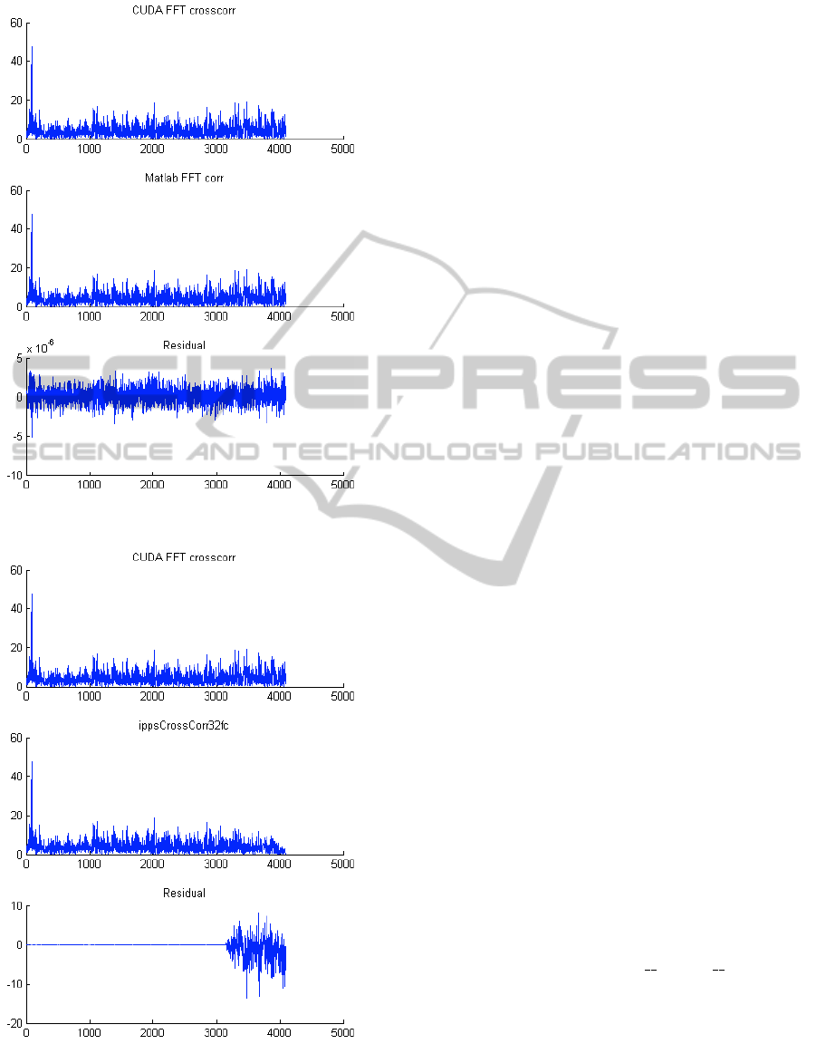
(a) CUDA vs. MATLAB.
(b) CUDA vs. IPP.
Figure 4: xCorr precision comparisons.
respectively 35% and 17% more add-mul operations
than Radix-2, but for certain sequence lengths Radix-
2 have high probability to hit a cache miss when look-
ing up for input operands. Once again, source code
for CUFFT for scheduling part, the one spawning the
computing threads, is not available in source format,
and so we can’t figure how authors handled such these
optimization problems.
These speculations, anyway, can suggest us an in-
teresting direction to focus attention to develop better
code for GPU. Some points:
• FFT stages show a pre-computable locality of in-
put arguments. it is possible to know in advance
which data chunks are needed in a processor in a
warp, for each step.
• Increasing local FFT size (Radix-3,4,5...N-k) will
increase computing time for node, but also will
represent a leap forward in stage’s map.
• Increasing local FFT size will increase probability
of cache miss in input argument, but this event is
related to local cache size.
4.1 Increasing Radix Size Approach
The few considerations above are valid for any com-
puting environment, as they’re resulting from algo-
rithmic analysis, but have great effect when applied
to NVidia GPUs context. All the points highlight
the need for local cache of arguments (see (Frigo
et al., 1999)), as picking them up from central mem-
ory would represent a great penalty in terms of laten-
cies and so for global execution times. Using global
memory in GPU is even more problematic than in
CPU, due to lack of pre-fetching units for each pro-
cessor in the array (there is a central memory handler
that pushes data to the common bus). Memory laten-
cies for GPU can sum up to 400 cycles for a single
transfer, and for this reason keeping low the risk of
cache miss is mandatory. Register file for each pro-
cessor in the array counts up to 32 entries, with low-
est latency access, but it would not be large enough to
improve data chunk size for thread.
In our help comes the shared memory structure,
16KBytes in pre-GT200 series of CUDA-enabled
GPUs, that has low time access too and can be used
just declaring variables with shared attribute.
NVCC will understand the memory map to be put
in shared separated space, and will push data closer
to processing units. This memory bank is shared on
Multiprocessor basis, and so many threads can access
in parallel to these information.
PECCS 2011 - International Conference on Pervasive and Embedded Computing and Communication Systems
270
4.2 Numerical Benchmarks
In (Volkov and Kazian, 2008) is shown an imple-
mentation of the FFT that achieves 160 GFlop/s on
the GeForce 8800 GTX, which is 3x faster than 50
GFlop/s offered by the CUFFT. It is designed for N =
512, which is hard-coded. Later in the text this ver-
sion will be referred as ”VV” code. The implemen-
tation also includes cases n = 8 and n = 64 working
in a special data layout. This implementation lacked
of support for inverse FFT, and moreover used a not
CUFFT-like calling scheme. It was so updated and
tested always against MATLAB to test precision and
CUFFT to benchmark performances. Special kernels
for Complex Conjugate operations have been sup-
plied externally, as reported in Listing 1. This latter
version, which is the most performant one, will be re-
ferred as ”VV+MV mod” later in the tables.
Using shared memory banks, and keeping N sizes
as power of two even in internal stages produces a
huge speedup, especially on longer sequences where
CUFFT likely spawns a very high number of comput-
ing threads. Using mixed radix sizes, moreover, it is
very hard to keep summation error as low as possi-
ble, as input terms for recombination are divided by
odd numbers, and more in general not for 2. For
this reason, on longer sequences, CUFFT shows a
not optimal precision measure and always higher than
VV+MV implementation. All the tests were executed
for FFT/iFFT sequences.
Some FFT benchmarks between standard CUFFT
design and VV+MV one. CUDA Toolkit v.2.1 on XP
32 bit used. Errors reported are in order of 1 ULP for
IEEE-754 32 bit data.
Device: GeForce 8600M GS
900 MHz clock, 256 MB memory
(CUDA Toolkit v. 2.1 - Windows XP 32 bit)
CUFFT VV+MV mod
N / Batch GFlop/s GB/s Err GF/s GB/s Error
8 / 524288 0.4 0.4 1.8 7.2 7.7 1.6
64 / 65536 2.5 1.4 2.3 10.5 5.6 2.2
512 / 8192 2.9 1.0 2.9 12.3 4.4 2.5
Device: GeForce 8800 GTS 512
1674 MHz clock, 512 MB memory
(CUDA Toolkit v. 2.1 - Windows XP 32 bit)
CUFFT VV+MV mod
N / Batch GFlop/s GB/s Err GF/s GB/s Error
8 / 524288 6.0 6.3 1.8 46.5 49.6 1.6
64 / 65536 37.6 20.1 2.3 94.4 50.3 2.2
512 / 8192 43.4 15.4 2.9 125.4 44.6 2.5
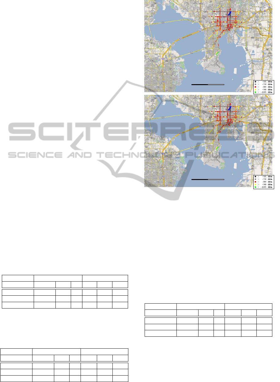
10 km!
10 km!
Figure 5: WIND3G Sensitivity improvements in a
GPS-tagged context.
In late 2009, NVidia released in 2.3 beta version
of their CUDA toolkit an updated CUFFT library,
with matches best performances above on longest se-
quences. Anyway, it still doesn’t handle properly
shorter length vectors (used often in multimedia pro-
cessing, expecially for noise samples in audio digital
restores).
Here are the same tests with updated values.
Device: GeForce 8800 GTS 512
1674 MHz clock, 512 MB memory
(CUDA Toolkit v. 2.3beta - Windows XP 32 bit)
CUFFT VV+MV mod
N / Batch GFlop/s GB/s Err GF/s GB/s Error
8 / 524288 5.7 6.1 1.7 45.9 49.0 1.6
64 / 65536 36.2 19.3 2.4 92.8 49.5 2.2
512 / 8192 129.1 45.9 2.1 121.9 43.4 2.5
5 CONCLUSIONS
UMTS code scrambling service has proven to be a
very demanding task in a production environment.
FAST TEMPLATE MATCHING FOR UMTS CODE KEYS WITH GRAPHICS HARDWARE
271

Before the CUDA solution was developed, the mobile
system to be used on the field should have been pow-
ered by a HPC-like system, with an obvious expen-
sive price tag - and really power hungry (> 2 × 400
Watts). On the road, such a requirement is to be
considered stressful for final users. The CUDA im-
provement enabled Wider Networks to ship a really
mobile system, based upon a standard off-the-shelf
GPU equipped laptop, to be used in companion to the
WIND3G Scanner. Total cost of ownership of such
a system is considerably lowered w.r.t to the original
setup. On the results side, the most notable improve-
ment is the higher sensitivity of the scanning proce-
dure, as shown in Figure 5 with a substantially lower
energy used in a shorter computation time slice. As
side effect, CPU+GPU usage, better scheduled in self-
containing computing threads, lowered the total load
to the underlying OS from ≥ 90% to < 35%.
REFERENCES
Bornkessel, C. and Wuschek, M. (2006). Exposure mea-
surements of modern digital broadband radio services.
Technical report, IMST GmbH, Test Centre EMC,
Kamp-Lintfort, Germany University of Applied Sci-
ences Deggendorf, Edlmairst, Deggendorf, Germany.
Frigo, M., Leiserson, C. E., Prokop, H., and Ramachan-
dran, S. (1999). Cache-oblivious algorithms. In
In Proc. 40th Annual Symposium on Foundations of
Computer Science, pages 285–397. IEEE Computer
Society Press.
Stasinski, R. and Potrymajo, J. (2004). Mixed-radix fft for
improving cache performance. EUSIPCO 2004, Pro-
ceedings of.
Tian, J., Xu, Y., Jiang, H., Luo, H., and Song, W. (2004).
Efficient algorithms of fft butterfly for ofdm systems.
In Emerging Technologies: Frontiers of Mobile and
Wireless Communication, 2004. Proceedings of the
IEEE 6th Circuits and Systems Symposium on, vol-
ume 2, pages 461–464 Vol.2.
Volkov, V. and Kazian, B. (2008). Fitting fft onto g80 ar-
chitecture. Technical Report CS 252, University of
California, Berkeley.
PECCS 2011 - International Conference on Pervasive and Embedded Computing and Communication Systems
272
