
AUGMENTED REALITY SYSTEM FOR KEYHOLE SURGERY
Performance and Accuracy Validation
Juan José Fuertes, Fernando López-Mir, Valery Naranjo, Mario Ortega
Eliseo Villanueva and Mariano Alcañiz
Instituto Interuniversitario de Investigación en Bioingeniería y Tecnología Orientada al Ser Humano
Universidad Politécnica de Valencia, Camino de Vera s/n, 46022 Valencia, Spain
Keywords: Augmented reality, 3D-virtual model, Validation, Laparoscopic surgery, Trocars.
Abstract: This work presents the performance and validation of an augmented reality (AR) system to help the surgeon
for trocar placement in laparoscopic surgery. The virtual organs are obtained by taking previous computed
tomography (CT) or magnetic resonance (MR) images of the patient and by applying segmentation
methods. Once in the operating theater, a real-time image of the patient is captured with a regular camera
that detects the patient’s pose (position + orientation) thanks to a marker that is centered on the navel. Then,
3D virtual organs are registered and fused with the real-time image, helping the surgeon to know the points,
at where, to place the trocars. To validate the system’s accuracy and performance, a 3D jar-model is
extracted from CT images which is then registered and fused with the real-time jar-image. An error of 2.91
millimeters is measured when the system accuracy is tested.
1 INTRODUCTION
Laparoscopy surgery is a surgical technique that
gives the surgeon a view into the patient’s internal
space with only small incisions. Nowadays, it offers
many advantages over traditional methods: smaller
incisions, lower probability of infection, the
prevention of consecutive operations, etc. There is a
faster recovery of the patient and fewer
psychological distresses. Nevertheless, laparoscopic
surgery has some drawbacks that are caused by the
inaccuracy of the points where the surgeon makes
keyhole incisions since a possible displacement
when the points are selected may give rise to a more
invasive surgery. Even experienced surgeons
sometimes require the replacement of trocars when
the surgery becomes complicated. Also, the lack of
direct vision and tactile perception as well as the
need for eye-hand coordination can be serious
problems. Therefore, the development of an accurate
system that helps surgeons improve their
performance is desirable.
The work that is developed in this project
validates the performance and accuracy of an
augmented reality system for placing trocars in
patients’ bodies. Many authors explain techniques
that attempt to improve and automate the location of
trocars: by taking CT or MR images and applying
automatic or semi-automatic segmentation methods,
a 3D virtual model of the organs is obtained. Then,
the surgeon must remember that information
because there is no software in the operation theater
that can show both the patient and the virtual model
at the same time. Chiu, Dey, Drangov, Boyd, and
Peters (2000) propose an external system for trocar
placement to obtain optimal access to the organs and
to simulate the endoscopic view observed by the
surgeon. The validation of the system is performed
using a phantom. Cannon, Stoll, Selha, Dupont,
Howe, and Torchiana (2003) convert the problem of
trocar placement into a mathematical problem that is
interesting for robot-assisted surgery. Adhami and
Coste-Manière (2003) convert the same problem
into an optimization problem where visibility and
dexterity are the cost function. The validation is
made with animals. Scheuering, Schenk, Schneider,
Preim, and Greiner (2003) use fiducials to register
the image and the virtual model, but these fiducials
must be visible when CT images and volume
reconstruction are obtained. In addition, they must
be in the same position once the patient is inside the
operation theater.
There are more techniques that are related to our
273
Fuertes J., López-Mir F., Naranjo V., Ortega M., Villanueva E. and Alcañiz M..
AUGMENTED REALITY SYSTEM FOR KEYHOLE SURGERY - Performance and Accuracy Validation.
DOI: 10.5220/0003316002730279
In Proceedings of the International Conference on Computer Graphics Theory and Applications (GRAPP-2011), pages 273-279
ISBN: 978-989-8425-45-4
Copyright
c
2011 SCITEPRESS (Science and Technology Publications, Lda.)
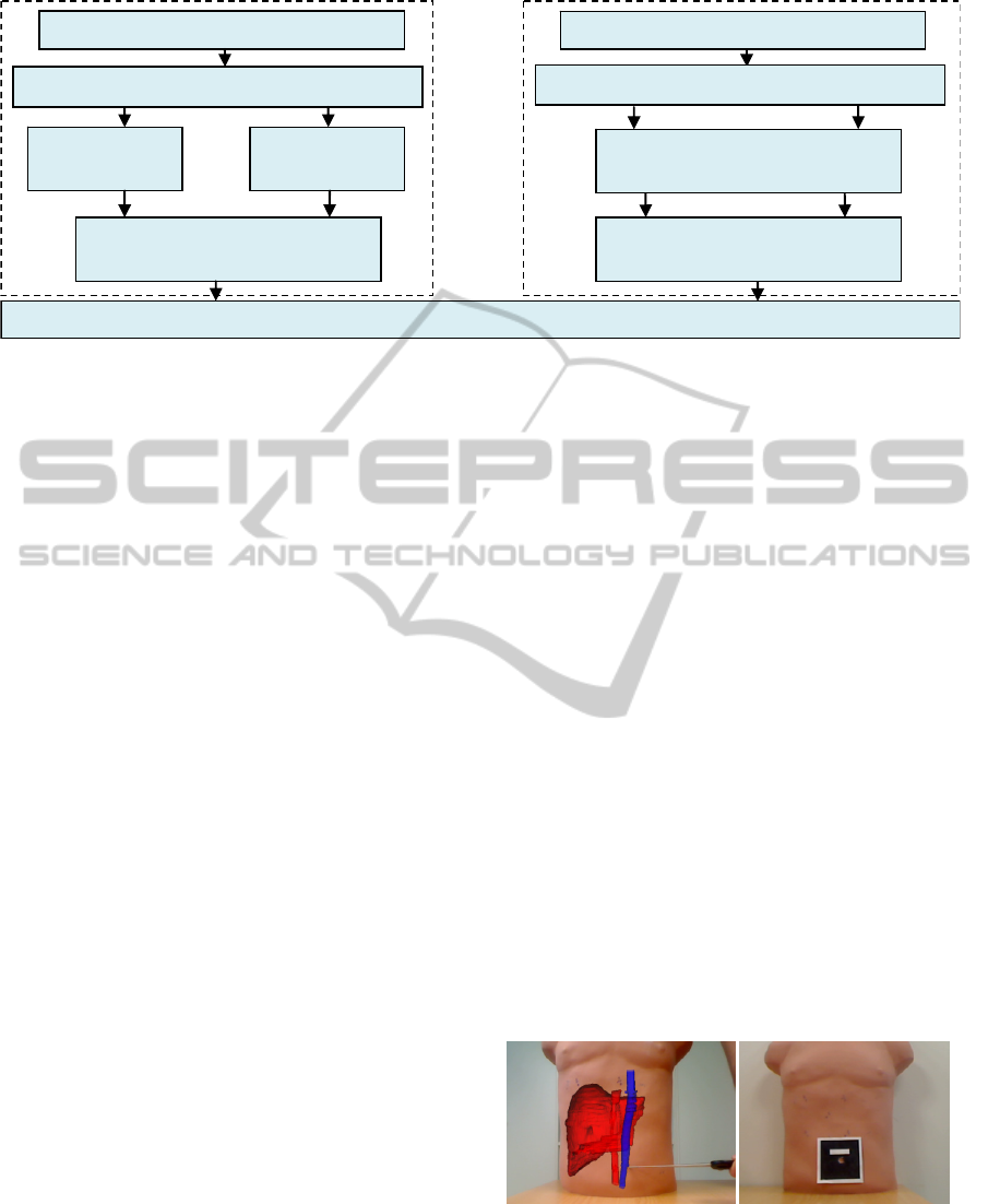
Figure 1: The block diagram of the AR system.
work, where the 3D virtual model is shown along
with the patient’s image once the patient is in the
operation theater. In this way, the surgeon has the
information in-situ when the operation is going to
start. Trevisan, Nicolas, Delville, Cornet d’Elzius
and Macq (2004) describe a technique to merge 3D
virtual models onto real scenes without tracking
markers. With the use of stereovision technique they
show a minimum error of 1 mm but an average error
of 1 cm in translation. Pandya, Siadat and Auner
(2005) propose a prototype medical Augmented
Reality system and they analyze the individual error
contributions and the system accuracy with an error
of 2.74 mm on average. Feuerstein, Wildhirt,
Bauernschmitt, and Navab (2005) propose an
automatic registration method where the fiducials
that are used to track the laparoscopic camera have
to be in the same place as in the CT images.
Afterwards, Feuerstein, Mussack, Heining and
Navab (2008) incorporate the superposition of the
3D virtual model in the laparoscopic camera.
Volonte, Bucher, Pugin, Carecchio, Sugimoto,
Ratib, and Morel (2010) perform registration and
fusion with the anatomical knowledge of the
surgeon. Our work incorporates a semi-automatic
registration and fusion method using markers, which
is validated with a 3D virtual model.
In summary, the goal of this project is to provide
the surgeon with information about locating trocars
in the patient. Section 2 shows a functional block
diagram of the augmented reality system (see Figure
1), explaining briefly how the 3D model is obtained
and located in a 3D work-screen-space. This section
also details the technique used when registering and
fusing. Section 3 and 4 show the empirical
experiments and the obtained results. Finally,
Section 5 presents conclusions and future work.
2 METHODOLOGY
2.1 Functional Block Diagram
This section explains how the AR system based on
the development of an application for laparoscopic
surgery works. It allows the surgeon to see “the
inside” of the patient’s body at the same time that
incisions are being made.
The AR system is divided into two blocks
(Figure 1). In the first block, before the operation
starts, the 3D virtual model of the organs is obtained
and is placed in a 3D-screen space together with the
images. Then, a change in the coordinate system in
the 3D-space is performed (Schroeder, Martin, and
Lorensen, 2006) in order to place the new origin in
the navel, keeping the orientation of the organs in
CT/MR images.
In the second block the real-time patient-image is
shown and the patient’s pose (position + orientation)
is automatically detected in the real world thanks to
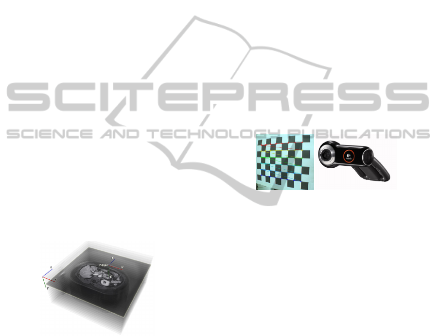
a marker centered on the navel (see Figure 2). This
is what allows the 3D model and the image to be
registered and fused.
(a) (b)
Figure 2 (a): A Binary hexadecimal code marker; (b): The
AR system of the patient’s organs.
Registration and fusion
Patient
3D model
extraction
MR/CT Images
3D virtual model focused on the new
origin
Locating the navel
Patient
Real-Time Image
Real-time image with a
detected-marker
Mark centered on patient’s navel
GRAPP 2011 - International Conference on Computer Graphics Theory and Applications
274
2.2 Obtaining a 3D Model
When the CT/MR images are being obtained, the
patient must be perfectly still while lying on the
stretcher with his/her back straight and centered on
both sides in order to determine the orientation of
the organs with respect to an initial coordinate
system. 512x512 pixels CT/MR images with a
spacing resolution of 0.938x0.938x3.0 millimeters
(mm) in each coordinate axis are obtained from a
General Electric Signa Excite 1.5T NVP 73800, and
then, the virtual model of different organs is
extracted by applying digital image processing,
especially a region growing algorithm and other
algorithms developed in the ITK library by Ibanez,
Schroeder and Cates (2005).
Once in the operation theater, the surgeon selects
the point of the navel in the CT/MR images thanks
to the application presented here. This application
establishes the new origin of the images and the
model at that point (see Figure 3). Thus, the organs
are oriented as in the CT/MR images, but in a
different position due to the coordinate change. The
new coordinate system after the change is:
x
= ∝+ x;
y
= β +y;
z
=
γ
+ z;
(1)
where α, β, and γ are the coordinates of the patient’s
navel with respect to the initial coordinate system
(x,y,z).
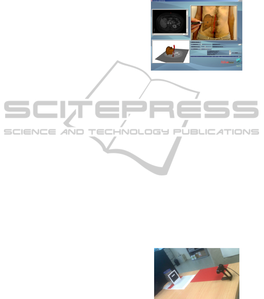
Figure 3: Coordinate system change.
2.3 Camera Calibration
To take the real-time image, a Logitech QuickCam
Pro 9000 webcam is used, which shows the area of
interest constantly. First, the camera is calibrated to
avoid possible errors when capturing images.
To do this, it is necessary to have different
captures of planar checkerboard patterns (see Figure
4), which should be different for each calibration
image. Zhang’s method (2000) is used for the
calibration step, taking the correspondence between
2D image points and 3D scene points over a number
of images.
The camera 3x3 intrinsic matrix K and the vector
γ with the distortion parameters have the following
form:
K =
f
su
0α
f
v
001
γ =
α
α
β
β
(2)
where f is the focal length, (u, v) is the camera
optical centre, α is the aspect ratio, and s is the
camera skew between the x- and y-axes; α
1
and α
2
are the radial distortion parameters, and β
1
and β
2
are
the tangential distortion parameters.
Next, a marker that is centered on the navel is
placed as shown in Figure 2 (a) to register and fuse
the image and the 3D virtual model of the organs. It
is advisable to keep the camera parallel to the
patient’s trunk in order to improve the accuracy of
the system, as is shown in Section 4.
(a) (b)
Figure 4 (a): Checkerboard that is used to calibrate the
camera; (b): A Logitech QuickCam Pro 9000 webcam.
2.4 Marker Detection, Registration,
and Fusion
A binary hexadecimal code marker of 8.45x8.45
centimeters is used in this step. First, the RGB
captured image is converted to a binary image, and
the edge of the marker is detected thanks to an
adaptive threshold algorithm based on the technique
of Pintaric (2003). Basically, “this technique
evaluates the mean pixel luminance over a
thresholding region of interest, which is defined as a
bounding rectangle around the marker axis-aligned
corner vertices in the screen-space”.
Afterwards, the relative marker position and
orientation with respect to the camera (view point)
can also be estimated from a planar structure when
the internal parameters are known, in order to apply
them to the virtual model. First, a 3D/2D
homography matrix must be calculated to later
obtain the projective matrix, as detailed by Martin-
Gutierrez, Saorín, Contero, Alcañiz, Pérez-López,
and Ortega (2010).
AUGMENTED REALITY SYSTEM FOR KEYHOLE SURGERY - Performance and Accuracy Validation
275
A 3D/2D correspondence (m, M) includes a 3D
point M and a 2D pixel point m, which are
represented as (X,Y,Z,1) and (x,y,1)
T
, respectively.
(m, M) is related by the 3x3 projective matrix P
i
as
Hartley and Zisserman (2003) show:
m= λ
P
M, P
=K
R
|
t
]
(3)
where R
i
is a 3x3 rotation matrix, t
i
is the translation
vector of the camera, and λ
i
is the homogeneous
scale factor that is dependent on P
i
M. Specifically,
considering the z=0 plane, the expression of the
homography that maps a point onto this plane and its
corresponding 2D point m under the perspective can
be recovered by writing:
x
y
1
=m=
λ
P
M=
λ
K
R
R
R
t
X
Y
0
1
=
λ
K
R
R
t
X
Y
1
(4)
where R
1
, R
2
, and R
3
are the columns of the matrix
R. Thus, (m, M) is related by a 3x3 matrix H
i
w
, called
homography matrix:
x
y
1
=
H
X
Y
1
, H
=K
R
R
t
(5)
Conversely, once H
i
w
and K are known, the
patient’s pose can be recovered from equations (3)
and (5), because R is a unit orthogonal matrix, as
Simon, Fitzgibbon, and Zisserman (2000) explain
(“the last column R
3
is given by the cross-product
R
1
×R
2
”):
K
H
=
R
R
t
, P
=K
R
R
R
t
(6)
Generally, the patient’s pose can be refined by
nonlinear minimization, since the anterior processes
are sensitive to noise and, therefore, a lack of
precision and the “jitter” phenomenon are produced.
In this case, the sum of the reprojection errors is
minimized, which is the squared distance between
the projection of the 3D points and their measured
2D coordinates. We can therefore write:
R
|t
]
=argmin
|
]
PM
− m
(7)
This equation will be solved using the
Levenberg–Marquardt (LM) algorithm proposed by
Marquardt (1963)
, providing a solution for the
problem “Nonlinear Least Squares Minimization”.
In this way, the 3D virtual model and the
patient’s image can be registered and fused,
allowing the surgeon to vary the transparency of the
image to see the patient’s image as shown in Figure
5. Just then, it is important for the patient to
maintain his/her position to avoid possible
registration errors.
Figure 5: The developed AR application. 3D-screen-space.
3 EXPERIMENTS
In order for the system to be validated by the
surgeon in the hospital, to test how the AR module
works, and to determine its accuracy, the following
experiments were performed using a 22 inch display,
a i5 4.0 GB RAM computer, and a regular camera.
Initially, 512x512 CT images with a spacing-
resolution of 0.488x0.488x0.625 mm per pixel were
extracted from a jar by means of a GE LightSpeed
VCT – 5124069 machine. The model used was a
500 ml DURAN GLS 80 jar with a diameter of 101
mm. The 3D virtual model was obtained by applying
a region growing algorithm to 8- and 12- bit images.
In the first experiment, to extract the virtual
model, a region growing algorithm was applied to 8-
bit images (which were rescaled from the initial 12-
bit images), taking the pixels between thresholds
230 and 255 gray scale. In the second experiment,
the region growing algorithm was applied to 12-bit
images, but taking the pixels between thresholds 150
and 2200 Hounsfield Units (HU).
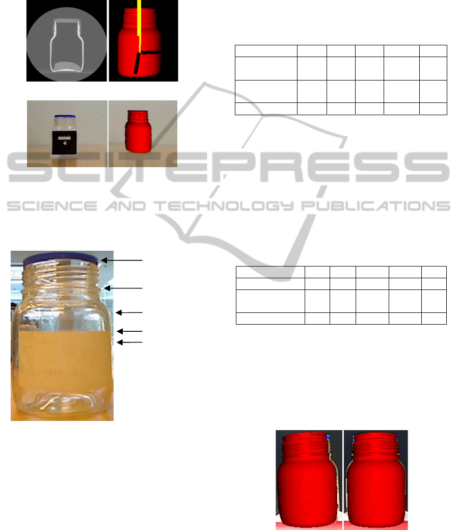
Figure 6: Experimental assembly of the system.
The camera was placed at a 90º degree angle
relative to the real jar, as shown in Figure 6. Then,
the middle point of the jar was selected in the CT
images as the new origin, and the marker was
centered on the jar. The registration and fusion were
GRAPP 2011 - International Conference on Computer Graphics Theory and Applications
276
performed at that moment, taking an image of the
real jar and the virtual jar to validate the system’s
accuracy. A full graphic example of the experiment
is shown in Figure 7.
(a) (b)
(c) (d)
Figure 7 (a): CT jar images; (b): 3D jar model in screen-
space; (c): Marker on the jar; (d): Real jar and virtual jar.
The positions where the accuracy was tested are
shown in Figure 8:
Figure 8: Positions where the measurements are taken.
4 RESULTS
In the first experiment, 8 test-samples were
performed to calculate the system’s accuracy by
placing the camera 50 cm away from the center of
the marker placed on the real jar and aligning it.
In each test, the real jar was removed and
relocated to the initial position. The 3D virtual
model of the jar was obtained from 8 bit-images.
The width of the real jar in the image was measured
in each position. The width of the 3D virtual jar was
also measured, obtaining the difference between the
widths (see Figure 9 (a)). After working out the
average of the 8 test samples, the results obtained in
pixels were:
Table 1: Results obtained with the virtual jar extracted
from 8-bit images.
JAR 0º POS. 1 POS. 2 POS. 3 POS. 4 Pref
Real Width
(pixels)
79 82 104 104 104
Model Width
(pixels)
73 78 100 99 99
Difference (pixels) 6 4 4 5 5
The average error was 5 pixels. Then, a new
model was obtained by applying a region growing
algorithm to 12 bit-images. Thus, it was possible to
compare both experiments in order to know if the
segmentation technique had any special influence on
the final accuracy. Eight samples were taken under
similar conditions to the first experiment (keeping
the camera at the same position and relocating the
jar). Table 2 shows the results:
Table 2: Results obtained with the virtual jar extracted
from 12-bit images.
JAR 0º POS. 1 POS. 2 POS. 3 POS. 4 Pref
Real Width (pixels) 79 82 104 104 104
Model Width
(pixels)
76 81 102 101 101
Difference (pixels) 3 1 2 3 3
The average error was 3 pixels. Since the width
of the real jar and the width in the image are known,
it is possible to calculate the equivalence mm-pixel.
In this case, 1 mm = 1.030 pixels, so the error
average was 2.913 millimeters.
As Table 2 shows, the error decreases due to the
higher accuracy when the model is segmented with a
region growing algorithm to 12-bit image resolution.
(a) (b)
Figure 9: (a): The real jar and virtual jar image with
camera position 0º relative to the real jar; (b): The real jar
and virtual jar with camera position 5º relative to the real
jar.
Pos. 1
Pos. 2
Pos. 3
Pos. 4
Pref
AUGMENTED REALITY SYSTEM FOR KEYHOLE SURGERY - Performance and Accuracy Validation
277
Three other experiments were performed to
analyze the evolution of the error relative to the
angular position of the camera. The camera angles
used were 5º, 10º, and 15º relative to the initial
position. In this case, since the virtual model hides
part of the real jar in the image (see Figure 9 (b)),
the difference in the right edge was calculated. Table
3 shows the results:
Table 3: Results obtained with 5º, 10º, and 15º deviation
camera and virtual jar extracted from 12-bit images.
JAR 5º POS. 1 POS. 2 POS. 3 POS. 4 Pref
Difference
(pixels)
4 2 2 3 3
JAR 10º POS. 1 POS. 2 POS. 3 POS. 4 Pref
Difference
(pixels)
5 4 4 4 4
JAR 15º POS. 1 POS. 2 POS. 3 POS. 4 Pref
Difference
(pixels)
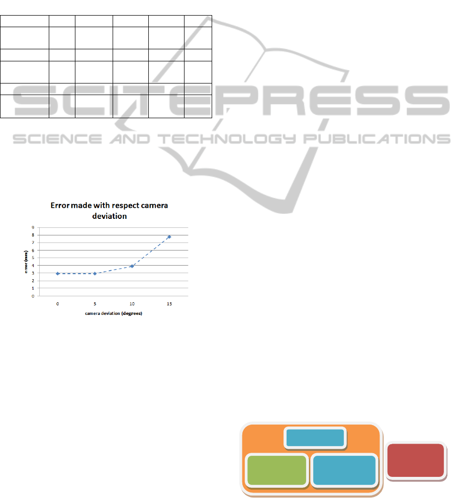
8 9 7 7 7
When the deviation was 5º, the error was similar
to case 1 (3 pixels), however, when it was 10º or 15º,
the error increased considerably (4 pixels and 8
pixels respectively). The higher the deviation
between the camera and the marker, the lower the
accuracy of the method, as Figure 10 shows.
Figure 10: Error made relative to the angular position of
the camera.
5 DISCUSSION
AND CONCLUSIONS
In this paper, we have presented a method to help
surgeons place trocars in laparoscopic surgery.
The minimum accuracy required for minimally
invasive surgery in the insertion of trocars is
approximately 2 centimeters (cm) because both skin
and trocars have a maximum error correction of 2
cm to compensate for locating errors as explained by
Feuerstein (2007). Therefore, it is important for the
CT/MR images to have a resolution that is higher
than 2 cm in all directions in order to segment and
obtain the 3D model correctly. This is a requisite
that is easy to carry out because the resolution of the
images used is only a few millimeters. If images had
a resolution lower than 2 cm, the system would not
be useful for surgeons.
Furthermore, since the segmentation method
employed in reconstruction of the 3D virtual organs
has a global influence on the system accuracy, it is
better to work with a high resolution image (12 bits)
than with 8-bit images (as proven in Section 4). If
the segmentation method or the image resolution are
not optimized, the global system will not work very
well even though the registration is adequate.
It is also important to emphasize how to place
the marker on the patient since it must be centered
on the navel and its base aligned horizontally. It
must be on a flat plane to avoid loss of accuracy
when the pose is calculated.
Analyzing the graphic and numerical results, we
can conclude that registration and fusion satisfy the
requirements. To be more thorough, the numerical
results that have been obtained lead to the
conclusion that the system can be used with patients
because, when it is well-calibrated, the error is only
about 3 mm. Again, note that the higher the
deviation between the camera and the marker, the
lower the accuracy of the method, emphasizing the
importance of camera position.
This result stands with regard to existing AR
methods: Pandya, Siadat and Auner (2005) showed
an error of 2.74 mm on average with standard
deviation of 0.81 mm in neurosurgery; Trevisan,
Nicolas, Delville, Cornet d’Elzius and Macq (2004)
presented an error of 1 mm but the object must be at
the centre of the sight (camera). Otherwise, the
system works badly; Feuerstein, Wildhirt,
Bauernschmitt and Navab (2005) showed a tracking
average error of 2.6 mm on a rigid phantom.
Another important topic is that the human’s liver
is deformable and non static, so it would desirable to
know the real-time deformation that the liver
undergoes. This is the reason why the AR system
proposed in this work belongs to a global system
that is currently being developed, as it is shown in
Figure 11.
Figure 11: General system for keyhole surgery.
Navigation
System
Segmentation
AR
System
Biomechanical
Model
GRAPP 2011 - International Conference on Computer Graphics Theory and Applications
278

All these assumptions (the patients must keep
their pose during scan and location of the trocars, the
liver is not rigid and dynamic, the surgeon aligns the
mark and places it on a flat plane, etc.) will be
overcome since the AR module is introduced in the
global system. It will allow the system to be
acceptable in a clinical environment once the
clinicians validate the accuracy and performance of
the system.
In addition, for future work, we plan the
insertion of tracking algorithms to control the
patient’s position, studying the different kinds of
markers.
ACKNOWLEDGEMENTS
This work has been supported in part by the project
IMIDTF/2009/83 and by private funds from
Beanaca s.a. We would like to express our deep
gratitude to the Hospital Clínica Benidorm for its
participation in this project.
REFERENCES
Adhami L. and Coste-Manière É. (2003). Optimal
planning for minimally invasive surgical robots. IEEE
Transactions on Robotics and Automation (Vol. 19,
Sup. 5, pp. 854–863).
Cannon J., Stoll J., Selha S., Dupont P., Howe R., and
Torchiana D. (2003). Port placement planning in
robot-assisted coronary artery bypass. IEEE
Transactions on Robotics and Automation, (Vol. 19,
pp. 912–917).
Chiu A. M., Dey D., Drangova M., Boyd W. D., and
Peters T. M. (2000). 3-D image guidance for
minimally invasive robotic coronary artery bypass.
The Heart Surgery Forum (Vol. 3, pp. 224–231).
Feuerstein M. (2007). Augmented Reality in laparoscopic
surgery. Tésis Facultad de Informática, Universidad
Politécnica de Múnich.
Feuerstein M., Mussack, T., Heining S. M. and Navab N.
(2008). Intra-operative laparoscope augmentation for
port placement and resection planning in minimally
invasive liver resection. IEEE Transactions on
Medical Imaging. (Vol. 32, Sup. 3, pp. 355-369).
Feuerstein M., Wildhirt S. M., Bauernschmitt R. and
Navab N. (2005). Automatic patient registration for
port placement in minimally invasive endoscopic
surgery, in Proc. Int’l Conf. Medical Image
Computing and Computer Assisted Intervention
(MICCAI). (Vol. 3750, pp. 287–294).
Gonzalez, Rafael C., Woods, Richard E. and Eddins,
Steven L., (2004). Digital Image Processing Using
MATLAB. Pearson Prentice Hall, (chapters 9-12),
Upper Saddle, NJ.
Hartley R. and Zisserman A. (2003). Multiple View
Geometry. In Computer Vision, Second Edition,
Cambridge University Press.
Ibanez, Schroeder, Ng, Cates. (2005). The ITK software
Guide, published by Kitware Inc,.
Marquardt Donald, (1963). An Algorithm for Least-
Squares Estimation of Nonlinear Parameters. SIAM
Journal on Applied Mathematics. (Vol. 11, pp. 431–
441).
Martin-Gutierrez, J., Saorin, J. L., Contero, M., Alcañiz
M., Pérez-López David C., Ortega M. (2010,
February). Education: Design and validation of an
augmented book for spatial abilities development in
engineering students. Computers and Graphics. (Vol.
34 (1), pp. 77-91).
Pandya A., Siadat M., Auner G. (2005). Desing,
implementation and accuracy of a prototype for
medical augmented reality. Computer Aided Surgery.
(Vol. 10 (1), pp. 23-35).
Pintaric T. (2003). An adaptive thresholding algorithm for
augmented reality toolkit. In: Proceedings CD of the
second IEEE international augmented reality toolkit
workshop, ART03.
Scheuering M., Schenk A., Schneider A., Preim B., and
Greiner G. (2003). Intraoperative augmented reality
for minimally invasive liver interventions. In Medical
Imaging 2003: Visualization, Image-Guided
Procedures, and Display. Proceedings of SPIE, (Vol.
5029, pp. 407-417).
Simon G., Fitzgibbon A. W., and Zisserman A., (2000,
October 5-6). Markerless Tracking using Planar
Structures in the Scene. Proceedings of ISAR2000,
(pp. 120-128).
Trevisan, D., Nicolas, V., Delville, P., d'Elzius, M. C. and
Macq, B., Towards markerless augmented medical
visualization. In: MICCAI International Workshop on
Augmented Environments for Medical Imaging and
Computer-aided Surgery.
Volonte, F., Bucher, P., Pugin, F., Carecchio, A.,
Sugimoto, M., Ratib, O., Morel, P. (2010 June). Mixed
reality for laparoscopic distal pancreatic resection.
(Vol. 5, Sup. 1, pp. 122-130).
Schroeder W., Martin K., Lorensen B. (2006).
The
Visualization Toolkit, Fourth Edition.)
Zhang Z. (2000). A flexible new technique for camera
calibration. IEEE Transactions on Pattern Analysis
and Machine Intelligence. (Vol. 22 (11), pp. 1330–
1334).
AUGMENTED REALITY SYSTEM FOR KEYHOLE SURGERY - Performance and Accuracy Validation
279
