
WEARABLE HUMAN BODY JOINT AND POSTURE
MEASURING SYSTEM
P. Dunias
Personal Monitoring Department, TNO Science and Industry, Eindhoven, The Netherlands
R. Gransier
Dept. Orthopaedic Surgery / Dept. Human Movement Sciences, Maastricht University Medical Centre (MUMC+)
Maastricht, The Netherlands
A. Jin, A. Statham
Personal Monitoring Department, TNO Science and Industry, Eindhoven, The Netherlands
P. Willems
Dept. Human Movement Sciences, Maastricht University, Maastricht, The Netherlands
Keywords: Human posture measurement device, Human joint measurement, Knee angle measurement.
Abstract: In many medical applications, especially the orthopaedic setting, ambulatory, monitoring of human joint
angles could be of substantial value to improving rehabilitation strategies and unravelling the
pathomechanics of many degenerative joint diseases (e.g. knee osteoarthritis). With the ageing of the
population and increasing incidence of obesity, the prevalence of degenerative joint diseases is increasing
(e.g. knee osteoarthritis is the single most common cause of pain and disability in middle-aged and older
adults. As an example, In case of osteoarthritis rehabilitation, it is critical to monitor the loading of the
affected joint during activities of daily living (ADL). These measurements allow monitoring of daily
activity patterns, joint angles and walking patterns, which could be of use in adjusting the applied therapy
depending on the results measured.
1 INTRODUCTION
In many medical applications ambulant, continuous
monitoring of human joint angles offers some
appealing added value to existing diagnosis and
rehabilitation means, particularly in areas such as
orthopaedics where monitoring the progress of the
therapy provides more insight regarding therapy
effectiveness. In case of arthritis rehabilitation, for
example, it is desirable to support the recommended
therapy by objectively monitoring the behaviour of
the patient outside the clinic or hospital. Based on
these measurements the specialist may check the
exact exercise of the patient and subsequently adjust
the applied therapy as necessary depending on the
results. In this case the walking pattern of the knee
joint was monitored as the most relevant to
pathologies of this nature.
In more complex situations, for example with
lower back pain prevention and/or rehabilitation, the
level of bending in all directions of the lower back
and the corresponding velocity could also be
monitored preventing situations that should be
avoided occurring by giving direct feedback to the
user.
As a consequence a number of publications have
reported ambulant instrumentation in recent years
(Gransier, 2010), (Riskowski, 2009). However, only
very few wearable systems are accurate enough in a
dynamic situation when, for instance, the user is
walking freely around. On the other hand there are
several systems measuring human joint angles and
268
Dunias P., Gransier R., Jin A., Statham A. and Willems P..
WEARABLE HUMAN BODY JOINT AND POSTURE MEASURING SYSTEM.
DOI: 10.5220/0003195202680272
In Proceedings of the International Conference on Biomedical Electronics and Devices (BIODEVICES-2011), pages 268-272
ISBN: 978-989-8425-37-9
Copyright
c
2011 SCITEPRESS (Science and Technology Publications, Lda.)

posture in a laboratory setting which are not of direct
interest in this study.
Comfort, accuracy and a user friendly interface
are key elements for such a device to work
successfully and be accepted in the medical world.
The basic element of the measuring system
introduced here is a very flexible, textile integrated
bending sensor. Several of these basis elements may
be combined in order to measure multi-dimensional
joints or more degrees of freedom of the human
body.
In the next sections the basic element required to
measure bending is described.
2 BENDING SENSOR
2.1 Single Bending Sensor
Measuring bending in our setting is based on the
change of electrical inductance of a very simple coil
(a loop of a conductive wire). It appears that the
inductance of a coil changes as the form of the coil
changes. The mutual inductance by a filamentary
circuit i on a filamentary circuit j is given by the
double integral:
lY
sdds
L
a
CC
i
π
μ
π
μ
44
0
2/][
0
+
⎟
⎟
⎠
⎞
⎜
⎜
⎝
⎛
′
⋅
≈
≥
′
∫∫
R
R
(1)
where
0
μ
denotes the magnetic constant (4πx10
-
7
H/m), C and C
′
are curves along the wires,
R
is
the distance between two points on respectively
C
and
C
′
. The vectors
ds
and
sd
′
represent
vectors along C and C
′
. When
R
becomes zero the
above equation becomes infinitive and therefore
there is an extra condition that
R
has to be larger
than half the thickness of the wire a. In that case the
inductance is only dependant on the radius a and its
length l and some factor Y denoting the current
distribution through the wire (typically Y=1/4).
When the form of the coil changes, the orientation of
ds
and
sd
′
changes and probably the distance
between them too. That results in a change of the
inductance of the coil.
As can be seen in equation (1) the mutual
position and orientation of the wire segments
determine the total inductance of the coil. It is these
elements that vary when the coil bends and thus
consequently changes the inductance
correspondingly. The wire used in this sensor is very
flexible and thin and integrated in a carrier e.g.. knee
brace, t-shirt, strap etc.
In the case that the bend of the coil is directly
connected to a single bending angle of a human joint
(knee, elbow etc.), a simple calibration can be used
to translate the bending inductance readings into an
absolute angle value. Calibration can be done using
a reference measuring system that simultaneously
measures the joint angle.
However in some cases, where the carrier may
be minimally shifted due to movement, the system
can be automatically recalibrated based on extra
information from accelerometers mounted on the
carrier.
2.2 Automatic Recalibration
In many applications where the bending sensors are
firmly attached to a body joint the translation from
inductance reading into joint angles can be done
once based on some discrete calibration
measurements. In particular in the case of a single
joint the calibration can be performed using
mechanical goniometry.
However, wearing a sensory system for a longer
time in a day inherently implies local shifting of the
system on the body, hence a discrepancy of the
calibration of the sensor. In addition, by fitting or
“putting on” the sensory system in a non-
reproducible way, the user introduces an additional
error in the calibration. To account for this an
automatic calibration was introduced based on extra
sensors mounted around the joint. A set of two tri-
axial accelerometers is placed above and below the
joint. When the user is in a steady state (sitting,
standing etc.) the readings of the accelerometers
may be used to calculate the absolute angle of the
joint. In static situations the accelerometers are only
measuring some proportion of the gravitational
force. Based on this, the angle between the
accelerometers is calculated. In dynamic situations
(walking, running etc.), the accelerometers “see”
simultaneously the gravitational force and the
human movement. In this case the calculation of the
joint angle is not possible using the accelerometers.
For this case the inductance measurement is used for
calculating the joint angle. Every static situation
during the day is used to (re)calibrate the bending
sensor compensating for any changes of the bending
sensor attachment on the human joint.
In summary, during static situations the
accelerometers are used to calculate the absolute
joint angle and calibrating the bending sensor, and in
dynamic situations only the calibrated bending
sensor is used.
WEARABLE HUMAN BODY JOINT AND POSTURE MEASURING SYSTEM
269
2.3 Validation of a Single Bending
Sensor
The goal of the validation study was to quantify the
knee angle error during normal activity (i.e.
standing, sitting, and walking). Therefore a single
bending sensor was attached to a knee brace with the
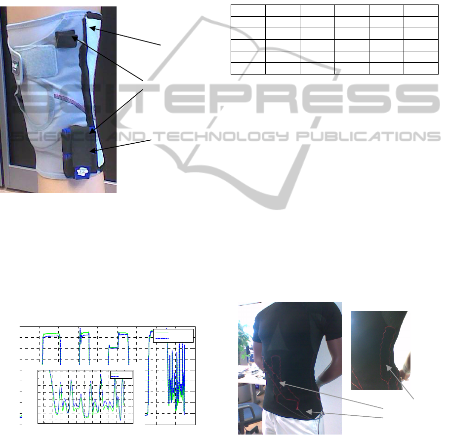
aim to measure the knee joint angle. In Figure 1 a
knee brace is depicted where the inductance loop is
attached.
Figure 1 Knee brace including bending/angle sensor.
Besides this the two accelerometers to be used
for the automatic calibration are attached on the
upper and lower parts of the brace. For validation
purposes, the knee angle was also measured using an
external VICON Camera system
(http://www.vicon.co). Figure 2 depicts a
measurement where the VICON knee angle and the
angle measured can be compared.
0 10 20 30 40 50 60 70 80 90
0
10
20
30
40
50
60
70
80
90
time [s]
angle [deg]
E:\KB\Maastricht06052010\Audrey\Audrey Trial 1.c3d
Vicon angle
KB angle
Figure 2: Measured and reference knee angle (static and
dynamic part).
The protocol followed consisted of a series of
common movements i.e standing, sitting (twice), leg
bending at four positions during sitting, standing,
sitting, standing and walking. A number of users
have been measured (5 reported in this paper), where
mostly five measurements have been performed per
user. A typical sample of the validation results are
shown in Table 1 depicting the maximal absolute
value of the error which is the difference between
the measured angle and the reference angle.
Table 1: Validation Result.
person a b. c d e
Mean 1.851 2.327 2.579 3.085 3.973
Abs. 1.559 2.617 2.093 3.577 3.504
Error 1.804 3.239 1.765 2.970 2.719
[deg] 1.464 2.313 2.446 3.204 2.130
1.421 2.051 2.186 4.246 2.523
An extended description of the validation
procedure and the corresponding validation results
of this specific single bending sensor are reported in
(Gransier et al., 2010) and (Riskowski et al. 2009).
2.4 Multiple Bending Sensor
A combination of the aforementioned single bending
sensor can be used in the case of measuring more
complex human joints, i.e. shoulder, wrist etc. Not
only joints but also body posture i.e. torso, can be
measured using a number of single bending sensors.
Suppose a human body part, the lower back for
example, which should be measured in terms of
three angles (flexion-extension, lateral flexion-
extension and rotation). Using a carrier, in this case
a shirt, it was possible to attach a number of wire-
loops on strategic positions around the body (see
Figure 3).
Figure 3: t-shirt crrier of osture multiple bending senor.
Measuring with a multiple bending sensor
consists of the following steps:
Inductance
bending
Sensors
75 76 77 78 79 80 81 82 83 84 85
10
20
30
40
50
60
70
80
time [s]
angle [ deg]
E:\ KB \M aastric ht 06052010\ Audrey\ Aud rey Trial 1.c 3d
Vic on angl e
KB an gle
Inductance
wire loop
Accelerometerers
Electronics
(acquisition,
storage)
BIODEVICES 2011 - International Conference on Biomedical Electronics and Devices
270
• Calibration or modeling the single
bending sensors separately
• Calculating the body posture based on
the readings of the single bending
sensors.
2.4.1 Calibration/Modelling
Calibrating a bending sensor really means modeling
the behavior of the inductance loop as function of
the angles or degrees of freedom of the body part
under consideration. Suppose a model of a single
bending sensor:
),( apSL
i
=
(2)
Where
m
R∈p represents the parameter set and
n
R∈a
the angles of the body part under
consideration. Here m number of parameters and n
degrees of freedom is assumed. Commonly there are
three degrees of freedom in the case of most human
joints and body parts.
Based on a number of measured inductances and
the corresponding body posture, the model can be
fitted by tuning the parameters.
2.4.2 Measuring Body Part Posture
Based on the calculated models for a number of
bending sensors it is then possible to calculate the
body part posture. The relationship between bending
sensor readings and body part posture is of a very
complex, non-linear, character. The problem of
calculating the body part posture has bee resolved to
provide an estimation of the real posture
1
.
2.5 Validation of a Multiple Bending
Sensor on a Dummy Body
Torso/Spine
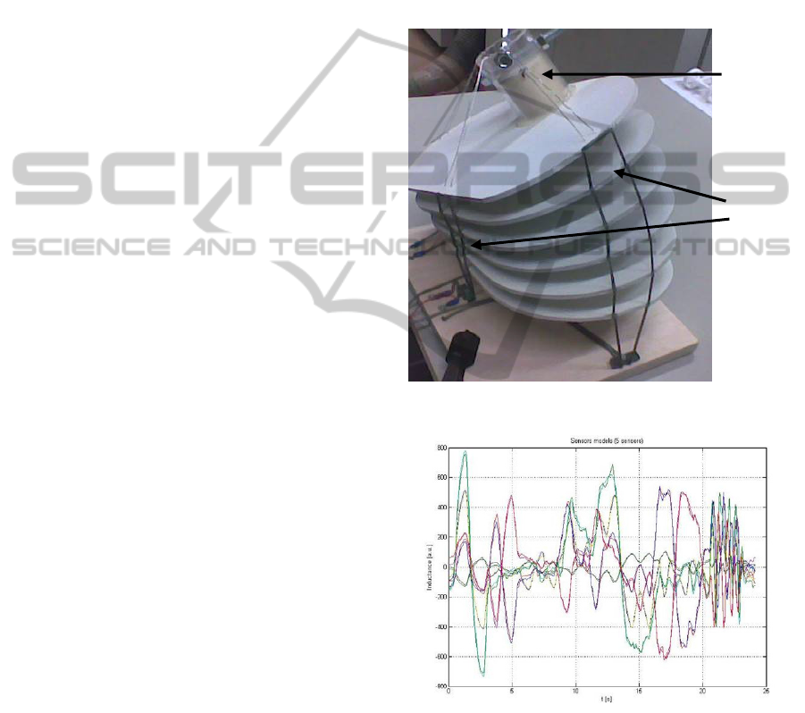
Comparable to the single angle bending sensor, for
the multiple bending sensor a carrier was chosen to
attach the inductance wires on the body in the form
of a tightly fitting elastic t-shirt. Before the system
could be implemented on the human body, a dummy
torso model was used to validate the modeling and
measuring method described in the previous
sections. An image of this torso model can be seen
in Figure 4. A flexible column represents the human
spine, with more rigid protruding discs modeling the
skeleton ribs. On this dummy model flexible
conductive wire loops are positioned in such a way
so as to form a multiple bending sensor. By
measuring with a VICON camera system and
simultaneously with the multiple bending sensor the
three degrees of freedom of this model (two bending
directions and one rotation around the spine) we
acquire data for modeling and validation purposes.
In this instance a model has been fitted for every
single bending sensor separately. In Figure 5 the
inductance models of the bending sensors are
depicted as described by equation (2). Based on
these sensor models the validation of the multiple
bending sensor has been investigated. The three
degrees of freedom of posture are then calculated.
Figure 4: Low back model.
Figure 5: Models of bending sensor model.
The error between the real angles and the
calculated angle in Figure 6, Figure 7 and Figure 8
for the three separate degrees of freedom in
reference to one sensor.
As appears, in x- and y-direction the angle error
is less than ±2 degrees, and in z-direction less than
±6 degrees.
“Spine”
Sensors
WEARABLE HUMAN BODY JOINT AND POSTURE MEASURING SYSTEM
271
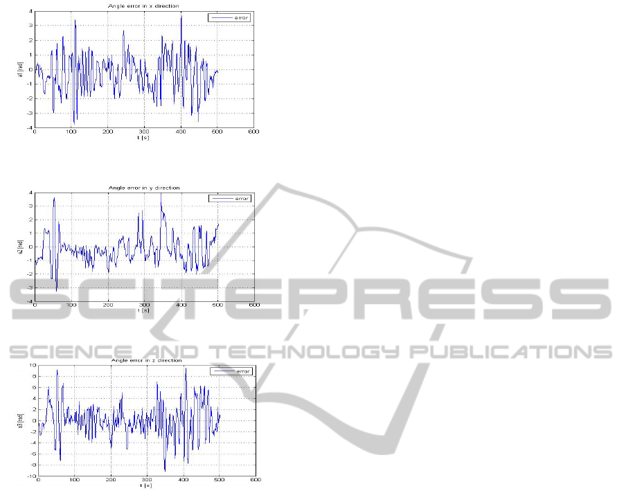
Figure 6: Angle error in x-direction.
Figure 7: Angle error in y-direction.
Figure 8: Angle error in z-direction.
3 CONCLUSIONS
A single bending human joint angle sensor system is
presented. The measuring accuracy of ±2 degrees
gives unique and sufficient basis for clinical
ambulant applications basis for further exploitation
of the technology.
In case of more complicated body moving parts
(shoulder, trunk etc.) a combination of single
bending sensors may be used to measure the relevant
degrees of freedom of the body part under
consideration. The accuracy results for flexion-
extension and lateral flexion-extension are very
promising (<2 degrees). In case of the torso rotation
angle we report higher errors (<6 degrees) and
depending on the application may meet the required
accuracy. Further investigation using realistic sensor
carriers i.e. t-shirt, is on going. Such a system (t-shirt
including sensors, electronics etc) has already been
built and tested.
ACKNOWLEDGMENTS
Special thanks to Merijn Wijnen of TNO Science &
Industry and Paul Willems of Maastricht University
for their support and assistance.
REFERENCES
Gransier, R., Dunias, P., Meijer, K., Deckers, P.,
Guldemond, N., Van Rhijn, L., 2010. Validating an
ambulant clinical monitoring system in Osteoarthritis
of the Knee; “The Knee Coach”. In Abstract
Orthopaedic Research Society.
Riskowski, J., Mikesky, A., Bahamonde, R., Burr, D.,
2009. Design and Validation of a Knee Brace with
Feedback to Reduce the Rate of Loading. In Journal of
Biomechanical Engineering, vol. 131.
Meijer, K., Gransier, R., Dunias, P., Deckers, P.,
Guldemond, N., Willems, P., Van Rhijn, L., 2010.
Determination of Gait Kinematics with a “Smart”
Knee Brace A Validation Study, In 6
th
World
Congress of Biomechanics.
BIODEVICES 2011 - International Conference on Biomedical Electronics and Devices
272
