
ONTOLOGY BASED UML2 COMPONENT
ARCHITECTURE GENERATION
Iman Poernomo, George Tsaramirsis
Department of Computing, King’s College London, U.K.
Mohammad Yamin
Department of Management Information Systems, King Abdelaziz University, Jeddah, Saudi Arabia
Keywords: MEASUR’s semantic analysis, Ontology chart, Component architecture.
Abstract: UML2 Component diagrams are mainly used to provide information about the technical architecture of the
information system. The paper shows how a component diagram can be auto-generated from an ontology
chart evolved from Semantic Analysis. A crowd management case study has been selected for its
complexity and its capacity to illustrate all the properties that are developed in the paper. It is anticipated
that the results of this paper would provide additional features for the system designers and developers.
1 INTRODUCTION
Component diagram is part of UML2 and is mainly
used to provide information about the technical
architecture of the information system. The main
idea behind is that a component is a container that
can contain class or other components as well as
their associations. Components of the same systems
may be in different physical locations and still be
associated and can collaborate with each other. The
same component may be serving multiple other
components at the same time.
MEASUR’s semantic analysis is a modelling
methodology for modelling organizations.
According to its founder R. Stamper, the method has
a number of benefits for information systems
(Stamper, 2008). The method identifies the agents –
physical and legal persons, affordances – substances
and their determiners – temporal attributes and
demands that every affordance is directly or
indirectly ontologically depended to an agent. An
affordance is directly linked with an agent if one of
its antecedents is an agent and indirectly if while
following the antecedents of its antecedent’s
recursively we end up to having an agent. Every
affordance must have an antecedent and can have up
to two antecedents. The method produces a diagram
called ontology chart. In this chart, every agent,
affordance and determiner will be mapped to a node
and the ontologically dependencies are shown by a
line. Ontology chart can be mapped to database
schemas, class diagrams (Ades, et al., 2007) and
other software engineering artefacts (Poernomo &
Tsaramirsis, 2008). In this paper we will take
advantage of the ontological dependencies of the
ontology charts and we will use them to produce
UML2 component diagrams.
2 RELATED WORK
There are a number of papers that demonstrate how
to transform an ontology chart to class diagram,
prototype system and software architecture. The two
most recent ones are the “SNF compliant
implementation” (Ades, et al., 2009) and “course
gain architectures” (Poernomo, et al., 2009) both
were presented at ICISO 2009. The first of these
papers compares two ways of implementing SNF
compliant software namely, the Model Driven
Architecture approach and the SNF native
technology approach. The paper concludes that
MDA is better for large scale development whereas
the SNF native technologies are better for smaller
systems. The paper also includes a simplified Meta
model of an ontology chart. However this paper did
not show how to build an ontology chart or how to
auto-generate component architecture. The second
314
Yamin M., Poernomo I. and Tsaramirsis G.
ONTOLOGY BASED UML2 COMPONENT ARCHITECTURE GENERATION.
DOI: 10.5220/0003269903140321
In Proceedings of the Twelfth International Conference on Informatics and Semiotics in Organisations (ICISO 2010), page
ISBN: 978-989-8425-26-3
Copyright
c
2010 by SCITEPRESS – Science and Technology Publications, Lda. All rights reserved
paper discusses the MDA approach and a theoretical
transformation but it focuses more on the
presentation of norms. It did not show how to do an
ontology chart and it did not give an example to
demonstrate how to auto-generate component
architecture. This paper builds on the weaknesses of
component architecture the above mentioned papers
and shows a step by step building of an ontology
chart. It also contains a more sophisticated Meta
Model for the extended version of the ontology
chart.
3 ONTOLOGY CHARTS
The ontology chart is a graphical representation the
ontologies identified by semantic analysis (Ades, et
al., 2007). Each node of the ontology chart
corresponds to an agent, affordance or determiner
and they are associated with each other via lines.
These lines show the ontological dependencies
between the nodes. This implies that the existence of
every ontologically dependant is also dependent on
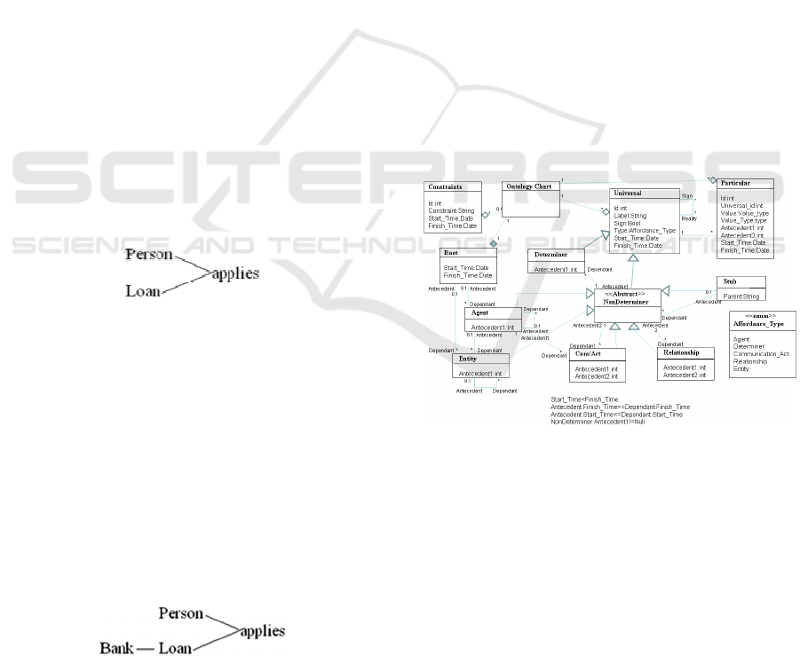
its antecedent. For example if we have a person
(agent) that applies (affordances) for a contract
(affordance). The application is ontologically
depended on the person and the loan. If either the
person or the loan siege to exist then the application
will siege to exist. The graphical representation of
this can be seen below.
Figure 1: Semantic unit example 1.
The position on the graph is important as it shows
the ontological dependencies. Everything on the
right site is ontologically depended on things at the
left site. All the association from the antecedents to
the dependants are one to many associations. The
method also has the advantage that it reveals hidden
requirements. Since every affordance must be
ontologically depended to an agent and loan is not
an agent, we know that loan must be depended
directly or indirectly to an agent. In this case the
loan is directly dependent to a bank that is an agent.
This is shown below.
Figure 2: Semantic unit example 2
In this paper we will use a similar version of the
ontology chart that was used by (Poernomo, et al.,
2009) According to that ontology chart Meta model
everything is an affordance. Affordances are divided
to agents, entities, determiners, communication acts
and other affordances. Communications acts can be
translated as “an agent is talking to another agent
about something”. Additionally we add the concept
of relationship. Relationships are affordances that
associate two other affordances. Every node has in
build start and finish times so it is capable of holding
temporal data. For example consider that ‘loan’ will
host all the loans, ‘applies’ will hold all the
applications and the ‘person’ will hold all the
persons. For simplicity, consider every node to be a
database table with start and finish time fields within
every table. Below we analyze a more complicated
ontology chart focused on the Hajj case study
(Yamin & Ades 2010) and (
Hajj Core, 2010
). We will
then use this as our source ontology chart and show
how it can be transformed to component
architecture.
4 THE SOURCE META MODEL
The following figure shows the Meta model of the
ontology chart.
Figure 3: The ontology chart Meta model.
An Ontology chart contains a root and it may
contain constraints, universals or particulars. A
universal may be associated with a lot of particulars.
A universal may be a sign of another universal.
Universals are generalization of determiner and non
determiner classes. A determiner has one non
determiner as its antecedent. Non determiners are
the generalization of Stubs, Agents, Entities,
Com/Acts and Relationships. A non determiner may
have a stub as its antecedent and a stub may have a
lot of non determiner as dependants. Stubs have no
antecedents. It worth to be noted, that we do not
ONTOLOGY BASED UML2 COMPONENT ARCHITECTURE GENERATION
315
allow a stub to have any determiners as its
dependants. If there are any determiners then they
should be placed to the schema where the stub exist
and not to this diagram. Also since determiners have
no dependants then there is no point on having a
stub determiner.
An agent may have another agent or the root as
its antecedent and Entities, Com/Acts as their
dependants. Additionally from Non Determiner class
they inherit the ability to have Determiners and
Relationships as their dependants.
Entities may have the root, an agent or another
entity as their antecedent. Entities may be
antecedents of com/acts and though inheritance of
non determiners, entities maybe antecedents of
relationships and determiners.
Com/Acts have two antecedents. The first
antecedent is an agent and the second antecedent
maybe any sign of a non determiner. Relationships
have two antecedents and they can be any non
determiners.
Finally following rules complete the Meta
model:
• The startTime attribute of every affordance
must be less than the finishTime attribute.
• The startTime of a dependant must be greater
than or equal to the startTime of its antecedent.
• The finishTime of a dependant must be less
than or equal to the finishTime of its
antecedent.
• Except the agent and the stub every other
affordance must have at least one antecedent.
Ontology charts can be valuable requirements
analysis artefacts but do not provide information
about the architecture of the system. In the following
section we will demonstrate how a component
diagram can be auto-generated from the above
ontology chart.
5 THE HAJJ ONTOLOGY CHART
Assuming that we want to develop a system that will
monitor the pilgrims (people) that participate in the
religious event called the Hajj (Yamin & Ades 2010)
and (
Hajj Core, 2010
). The Hajj is an annual
pilgrimage to Mecca and the surrounding areas in
Saudi Arabia. About four million people from
various parts of the globe perform Hajj every year.
During the travel and rituals, many pilgrims go
missing; some become sick, needing medical
attention. There may arise many other problems
including overcrowding (resulting in stampede),
traffic jams, hazards and accidents. We want to
model a system which would allow us to capture all
the data and possible locations of pilgrimages for
better crowd management by the authorities. The
following ontology chart shows our proposal for the
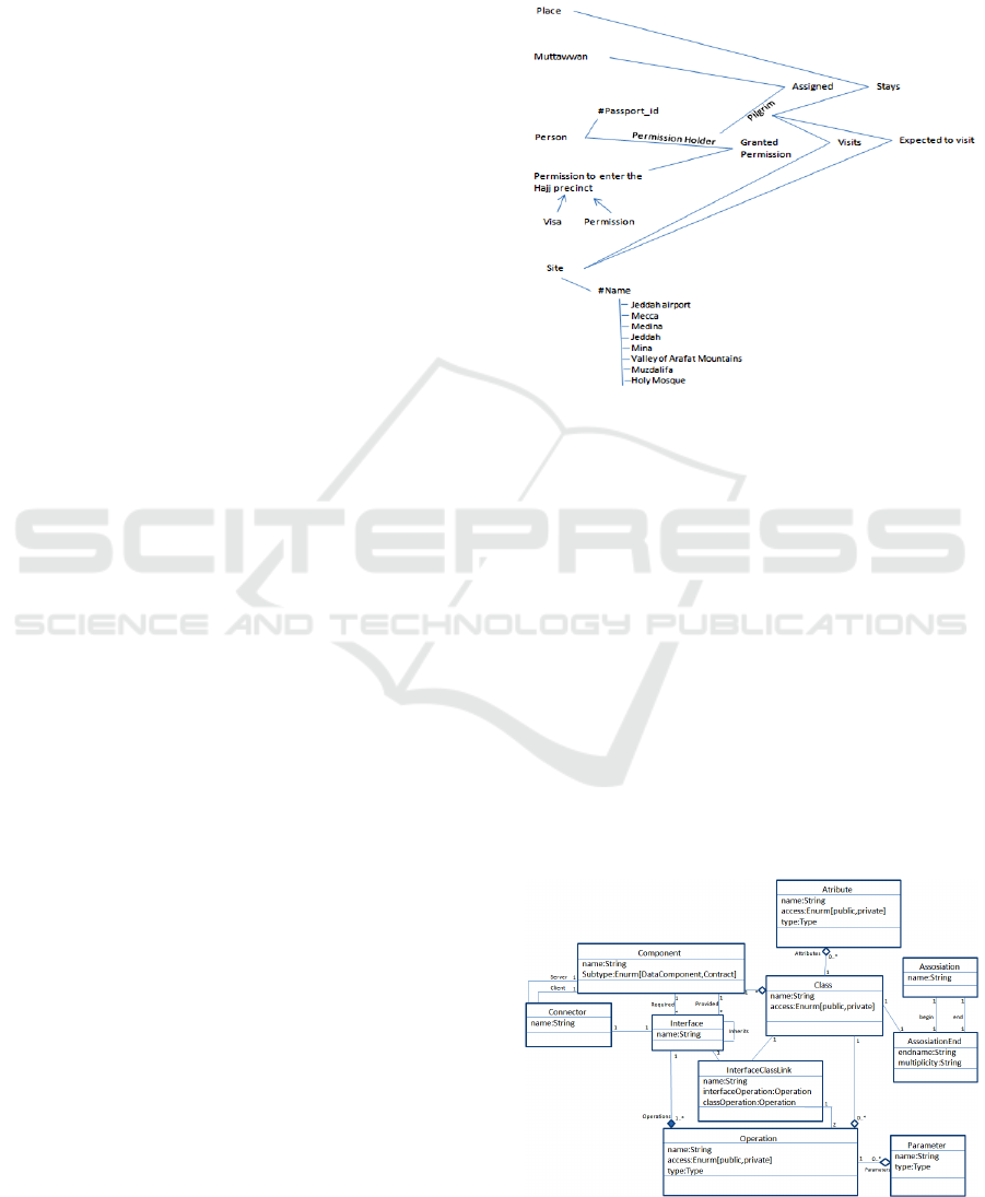
Figure 4: The Hajj Ontology Chart
The above ontology chart states that a person that
owns a passport can be granted permission to enter
the hajj precinct. There are two types of permissions
namely, “visa” and “permission”. The permission
holder is assigned to a Hajj Management group,
known as Muttawaf, who is responsible for
organising travel and accommodation within the
Hajj precinct. A permission holder is considered as a
pilgrim after she/he is assigned to a Muttawaf group.
Pilgrims stay at a number of places, visit sites and
participate in rituals at a number sites.
6 TARGET META MODEL
Below is the Meta model for the component diagram
that will be used as target architecture in this paper.
Figure 5: Component diagram Meta model
ICISO 2010 - International Conference on Informatics and Semiotics in Organisations
316
The Component diagram in the above figure
describes a component that has a name and that
could contain multiple classes inside. A class
contains attributes and operations. Each operation
may have many parameters. Two classes can be
associated together. Every association has a
beginning and an end. Both ends may have a label
and multiplicity. A component can be used by or use
other components via interfaces. Interfaces have a
name and operations. An interface can be linked
with a class inside the component via the
interfaceClassLink. The connector links two
components together via an interface. One of these
two components will the client and the other will be
the server. In our transformation we will generate
components and two sub types of components. The
data components and the contract components. The
data components will be simple links to a database.
The contract components will be a link between two
other components and a data component.
7 TRANSFORMATION
A very important aspect of the transformation will
be to produce a design capable of storing all
temporal data. This includes storing all the
component data as well as the data that come as a
result of the interaction of the component with other
components.
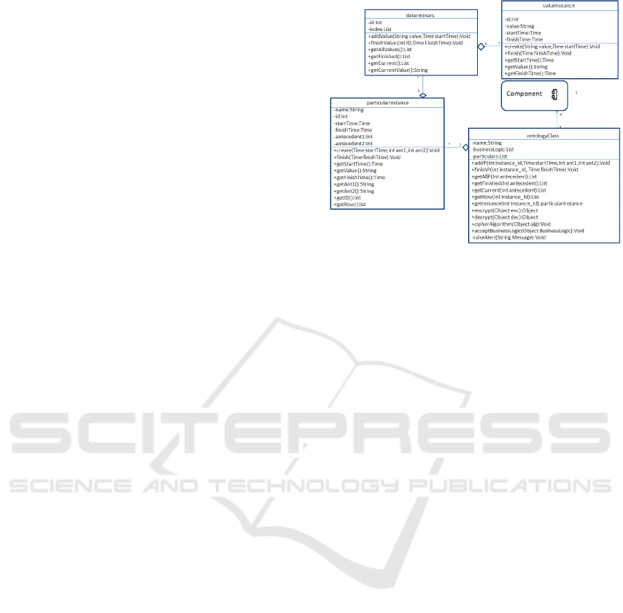
7.1 The Inner Structure
Every affordance that is transformed to components
will have its determiners stored in a class called
ParticularInstance that will be in a class of type
ontologyClass within the component. Any non
determiner affordances directly ontologically
depended to the component, that will not be
transformed to component will be transformed to a
class called ontologyClass and is placed in the
antecedent component.
Figure 6: The inner structure
A brief description of the methods follows.
7.1.1 Particular Instance Class
addValue (String value,Time startTime):Void
The addValue method is used for adding a value
instance to the universal linked list. The method
takes the name of the determiner, the value and the
start time as input parameters and it does not return
any value. This method calls the create method of
the valueInstance class.
finishValue(int id,Time finishTime):Void
The finishP is used to finish a value instance. For
example if the telephone of a person is no more
valid then we may want to terminate the current
phone number. We can do this by calling the
finishValue method with the id of the value instance
that we want to finish and the finish time.
getAllValues():List
The getAllValues method returns a list with the
value instances. Both current and finished instances
will be displayed.
getFinished():List
The getFinished method takes returns a list of all all
valueInstance instances that have finishTime value
before the current system date. This way we can get
all previous and finished instances like previous
telephone numbers or previous addresses and so on.
getCurrent():List
The getCurrent method returns a linkedlist of all all
valueInstanceinstances that have no finishTime
value or the finishTime value is later than the current
system date. This way we can get a active values
such as all current telephone numbers or all current
addresses of a person.
ONTOLOGY BASED UML2 COMPONENT ARCHITECTURE GENERATION
317

getCurrentValue():String
The getCurrentValue method can be used only if
there is only one active value instance. The method
will use the getCurrent method and will check if the
size is one. If the size is different than one is going
to return null else it is going to call the getValue
method of the valueInstance class. This method
hides all the complexity of the structure from a
programmer who may want to store singe values as
determiners. For example maybe we don’t care for
the history of names of a person and we just care for
its current name. However, if we ever need it the
functionality is there.
7.1.2 The ontologyClass
Apart from determiners we also store all other
affordances that are directly ontologically depended
to the component but are not themselves transformed
to a component. For example, let us assume that a
person owns a book. The person is an agent and will
be transformed to a component, ‘owns’ is a
relationship and ‘book’ is an entity and will be
transformed to an entity component. In this case the
relationship ‘owns’ will be converted to a
ontologyClass class and placed in the person
component. The ontologyClass class will have the
name of the affordance, in our examples this will be
‘owns’ and instances of various ownerships. This is
because a person may have owned different books in
the past or owns more than one books in the present.
Its ownership instance will hold information such as
which person owned which books and when. The
ontologyClass have methods for adding, searching,
and finishing instances. Each particularInstance can
have zero to many determiners within it. The
methods of the ontologyClass are explained below:
addP(Time startTime,int ant1,int ant2):Void
The addP method is used to add instances of
particular instances into the universal linked list. The
method takes as parameters the start time, the first
antecedent and the second antecedent. For example
if George owns a book, then we need to give the
start time of the ownership, the id of George and the
id of the book.
finishP(int p_id,Time finishTime):Void
The method finishP takes the as parameters the id of
the particular and the finishTime. In this way
instance is “terminated”. It is worth noting that we
never delete anything. Every time we want to
terminate something we put finish time.
getAllP(null,int Antecedent1, int
antecedent2):List
The getAllP method will return a list with all the
valueInstances instances if no parameter is passed. If
the first antecedent is passed as parameter then it
will return all the instances where the first
antecedent is equal to the parameter. If the second
antecedent is passed as parameter the it will return
all instance where the second antecedent is equal to
the parameter. This way we can get all instances or
all instances associated with the first or the second
antecedent. For example if a person own a book, we
can get all the person who owns books, or all the
books that a person holds or all the persons that hold
a book.
getFinished(null,int antecedent,int
Antecedent2):List
The getFinished method returns a list of all
valueInstance instances that have finishTime value
before the current system date. This way we can get
all previous and finished instances like previous
ownerships, owners, things owned and so on. Like
the getAllP method, the getFinished can take null,
the first or the second antecedent as parameter. So it
can return all instances, or all instances associated
with one of the two antecedents.
getCurrent(null,int antecedent1,int
antecedent2):List
The getCurrent method returns a linkedlist of all
valueInstance instances that have no finishTime
value or the finishTime value is later than the current
system date. Like the getAllP method, the
getFinished can take null, the first or the second
antecedent as parameter. So it can return all
instances, or all instances associated with one of the
two antecedents.
getRow(Int P_Id):List
The getRow method takes a particular id as
parameter and returns a list with the last value of
every determiner and start time for a given particular
id.
getInstance(Int
particular_id):particularInstance
The operation returns the particularInstance from the
universal list where the id is equal to the parameter.
encrypt(Object enc):Object
The encrypt method is used to encrypt data
decrypt (Object enc):Object
The decrypt method is used to decrypt data
cipherAlgorithm(Object alg):Void
The inversion of control pattern was used to secure
the data of the system. The cipherAlgorithm method
is used to pass the encrypt or decrypt algorithm.
ICISO 2010 - International Conference on Informatics and Semiotics in Organisations
318

raiseAlert(String Message):Void
The raiseAlert method is used by all other methods
of the ontologyClass if they want to report an
anomaly. The method will then report to a log and
other appropriate systems that can take action.
acceptBusinessLogic(Object
businessLogic):Void
All the dynamic rules of the system should separate
from the instances. We propose storing business
logic instances in a list and execute them
accordingly. Similar with the Strategy Design
pattern, this method accepts instances of Business
Logic and stores them in the list businessLogic. This
allow us to change the dynamic behaviour of the
system even at run time.
All the ‘get’ methods of determiner and
ontologyClass class will be linked with the ‘provide’
interface of the component while the interaction
methods will be linked through the require interface
with the transformation of the second antecedent of
the affordance.
The transformation T will transform the ontology
chart (OC) to component diagram (CD). Since
ontology chart resides at the computational
independent model level and the component diagram
at the platform independent model level, this is a
CIM to PIM transformation.
7.1.3 Inner Structure Explaination
Each affordance such as Person can have many
determiners ontologically dependent on it, such as
name, telephone, address and so on. Each
determiner can have many instances associated with
it, for example a person may had a previous name,
or many telephones, previous addresses and so on.
The determiners class will be responsible for holding
this information. The class has two linked lists called
index and universal. The is used for storing meta
information about the determiners, such as the type
of the value that they hold, their name and unique id.
The linked list universal holds instances of the class
valueInstance that will hold the name of the
determiner, the value, the start time and the finish
time. The determiners class methods for searching,
retrieving and adding instances of determiners.
Apart from determiners we also store all other
affordances that are directly ontologically dependent
to the component but do not themselves transform to
a component. For example, let us assume that a
person owns a book. The person is an agent and will
be transformed to a component, ‘owns’ is a
relationship and ‘book’ is an entity which would be
transformed to an entity component. In this case the
relationship ‘owns’ would be converted to a
ontologyClass class and placed in the person
component. The ontologyClass class will have the
name of the affordance; in our examples this will be
owns and instances of various ownerships. This is
because a person may have owned different books
over the past or owns more than one books at
present. Its ownership instance will hold information
such as which person owned which books and when.
The ontologyClass has methods for adding,
searching, and finishing instances. Each
particularInstance can have zero to many
determiners within it. All the get methods of
determiner and ontologyClass class will be linked
with the provide interface of the component while
the interaction methods will be linked through the
require interface with the transformation of the
second antecedent of the affordance.
Every time we generate a component we include
the structure definer above. This way every time we
generate a component the system will generate a
class inside which will have the name of the label of
the affordance and will be of type ontologyClass.
This class will have a list inside, which will store all
the particulars and their determiners value. To do
this, we need to define a new type which will have
the name of the label of the affordance and the word
instance. Inside this class, we will add attributes of
type determiner for every determiner dependant that
the affordance has. Then we will create two
provided interfaces and link the ontology class with
them. We will call them ReadOnlyInterface and
ReadWriteInterface. The first will include all the
public get methods of the ontologyClass while the
second will include all the public methods of the
ontologyClass.
7.2 Linking Component Interfaces
Before linking components together we need to
understand the permissions rights. As we have
shown in the previous section, affordances have
antecedents and dependants. The dependant is
ontologically depended to the antecedent. The
multiplicity is one to many from the antecedent to
the dependant. An affordance can be ontologically
depended to another, directly or indirectly. For
example consider a bank, a loan that the bank offers
and a determiner amount.
The property of the loan is directly ontologically
depended on the loan and indirectly to the bank.
Affordances have less access rights to the
ONTOLOGY BASED UML2 COMPONENT ARCHITECTURE GENERATION
319
affordances that they are ontologically depended and
more access right to the affordances that are
depended on them.
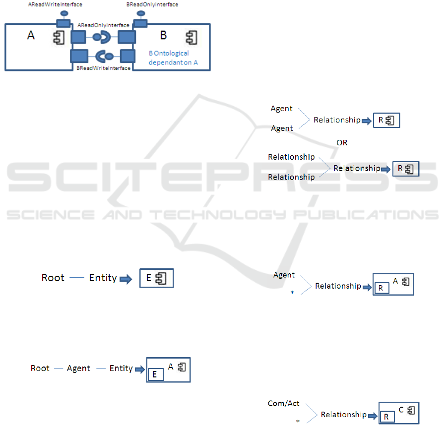
Based on the above if we want to connect the
interfaces generated by T(A) and T(B) and B is
ontologically depended on A, then B will be
connected to the ReadOnly interface of A and A will
be connected with the ReadWrite Interface of B.
This means that the dependant has read only access
to its antecedent while the antecedent has full access
to its dependants. The following figure shows this.
Figure 7: Linking component interfaces.
7.3 The Transformation
7.3.1 Dealing with Agents
For every agent generate a component. If the agent
has another agent as its antecedent, then link the
interfaces.
7.3.2 Dealing with Entities
Entities have only one antecedent and this can be the
root, an agent or another entity.
If the first antecedent is a root then this entity
will be a component.
Figure 8: Entity to component.
If the antecedent is an agent then transform the
entity to an ontologyClass and placed in the agents’
component.
Figure 9: Entity to ontologyClass.
If the antecedent is an entity, we need to check if the
first antecedent of the antecedent is an entity and if
yes check its first antecedent and so on until we
reach root or an agent.
7.3.3 Dealing with Communication Acts
A communication act is a communication between
two agents about something. The first antecedent of
the communication act is an agent and the second is
a sign. The sign represents the affordance, the agents
are communication actors. Since self is a
communication act at least the first antecedent of
that sign is an agent. The second may or may not be
an agent.
For every communication act we generate a
component. Then we link the interfaces with its
antecedents.
7.3.4 Dealing with Relationships
A relationship will only be transformed to a
component if both antecedents are agent or if both
antecedents are relationships. In all other cases it
will be an instance of ontologyClass.
Figure 10: Relationship to component.
If one of the antecedents is an agent and the other is
anything else, then R will be transformed to an
instance of ontologyClass and placed in the
T(agent).
Figure 11: Relationship to ontologyClass 1.
The communication act is the second stronger
category. So if an agent is not present and a
communication act is present then it should go in the
communication act. If there are two communication
acts, it should go in the first antecedent.
Figure 12: Relationship to ontologyClass 2.
If no agents or communication acts are present
we have following cases:
ICISO 2010 - International Conference on Informatics and Semiotics in Organisations
320
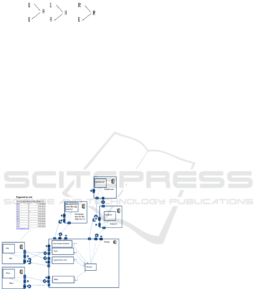
Figure 13: Relationship to ontology class 3
If any of the antecedents has been turned into a
component then turn the Relationship to an
ontologyClass and place it in the component. If both
antecedents are entities and none of them has been
turned into a component, then find in which
component the first antecedents is located and place
the ontologyClass there. Else if one of the
antecedents is relationship and the other is entity
place the ontologyClass in the same component with
the relationship.
8 THE AUTO-GENERATED
COMPONENT
ARCHITECTURE
The following Figure shows the generated
component diagram, describing the architecture of
the system.
Figure 14: The auto-generated component architecture.
Permission granted, visits, excepted to visit and stays
nodes of the ontology chart, have been converted to
ontologyClasses in the person component. Person and
muttawan have been converted to components because
they are agents. The assigned relationship has been
converted to a component because both its antecedents are
agents. Place and site entities have been turned into
components because their antecedent is the root.
9 CONCLUSIONS
Design component architecture is a task usually
performed by human experts. To the best of our
knowledge, we have proved that ontology chart is
semantically rich enough which is capable to being
transformed to component architecture model. In
this paper, we have presented a possible solution for
auto-transforming ontology charts to component
architecture models. The purpose of this paper has
been to show that such a generation is possible.
Other transformations can be defined which would
allow auto-generation of component architecture
tailored to specific problems.
ACKNOWLEDGEMENTS
This work would have not been possible without the
initial work of Ronald Stamper on semantic analysis.
We would also like to thank Yasser Ades who aided
us with the evaluation of the Hajj ontology chart.
REFERENCES
Ades Y, Ben-Oman F, Poernomo I, Tsaramirsis G 2007.
Mapping Ontology Charts to Class Diagrams,
ICOS2007
Ades Y, Karimi-Sani N, Nistazakis M, Poernomo I,
Yamin M, Tsaramirsis G, 2009. Implementing SNF-
compliant software: MDA and Native technology,
proceedings of ICISO 2009, p71-p78
Poernomo I, Tsaramirsis G 2008. Prototype Generation
From Ontology Charts, ITNG 2008
Poernomo I, Tsaramirsis G, Zhang N, 2009. Course-gain
Architectures from business requirements – an
organizational semiotics approach, proceedings of
ICISO 2009, p124-p129
Stamper R, 2008. MEASUR – Methods of theory and
analysis of information systems, Proceedings of IWRA
2008. P135-p160.
Yamin M, Ades Y, Crowd Management with RFID &
Wireless Technologies, International Journal of
Wireless & Mobile Networks (IJWMN), 2010
Hajj Core (Official Hajj Research Organization), http://
www.hajjcore.com/news_detail.asp?ID=4, Last
Accessed on 31/6/2010
ONTOLOGY BASED UML2 COMPONENT ARCHITECTURE GENERATION
321
