
Experiments of Discovery Services Interconnection
?
Adrien Laurence
1
, J
´
er
ˆ
ome Le Moulec
1
, Jacques Madelaine
1
and Ivan Bedini
2
1
GREYC – CNRS UMR 6072, Bd Mar
´
echal Juin, F-14000 Caen, France
2
Orange Labs., 42, rue des Coutures, F-14000 Caen, France
Abstract. This paper presents a platform called IOTA, an open implementation
of the EPCglobal architecture. It aims to collect and to store events about object
involving in a given supply chain. Iota uses a Petri net simulator to emulate the
lower layers including the RFID readers. Iota focuses on the design of a non cen-
tralized Discovery Services and experiments in a real network environment. This
paper presents the experiments of a solution for distributed Discovery Services
and its impact on the overall architecture in terms of performance issues.
1 Introduction
The usage of RFID tags is now so common that we urgently need for efficient lookup
services among the events tracing the tags. We currently develop a platform called IOTA
(Internet Of things Application) in order to experiment events storage and lookup ser-
vices. It is deployed over four locations linked with a real wide area network.
IOTA satisfies the EPCglobal requirements and implements the already published
standards. If the storage and the data sharing of the events capture is standardized, the
data search and the lookup services are still at a proposal level. At the moment, these
propositions does not take distributed control into account. This option raises some
political difficulties as organizations generally wish to keep control over these data. We
propose a solution to avoid monolithic discovery services. This solution has a overhead
cost in terms of additional messages and storage that we study in this paper. This paper
presents the results of the first tests we have run on the IOTA platform.
The paper is organized as follows. Section 2 presents the Epcglobal architecture
organized in layers. Section 3 recalls the different strategies for decentralized discovery
services. The use case used for our simulation is described in Section 4. Section 5
presents the architecture of our platform and details the non standard components we
have created. Section 6 discusses the tests results. Finally, we give in Section 7 some
open issues.
2 EPCglobal Architecture Overview
The EPCglobal architecture is composed of dedicated components grouped in four lay-
ers (see Figure 1). The lower layer deals with RFID tag reading. Each tag contains a
?
This work is carried out within the framework of a french national project: ANR WINGS; this
work is supported in part by the french CPER Basse-Normandie.
Laurence A., Le Moulec J., Madelaine J. and Bedini I.
Experiments of Discovery Services Interconnection.
DOI: 10.5220/0003027200400052
In Proceedings of the 4th International Workshop on RFID Technology - Concepts, Applications, Challenges (ICEIS 2010), page
ISBN: 978-989-8425-11-9
Copyright
c
2010 by SCITEPRESS – Science and Technology Publications, Lda. All rights reserved
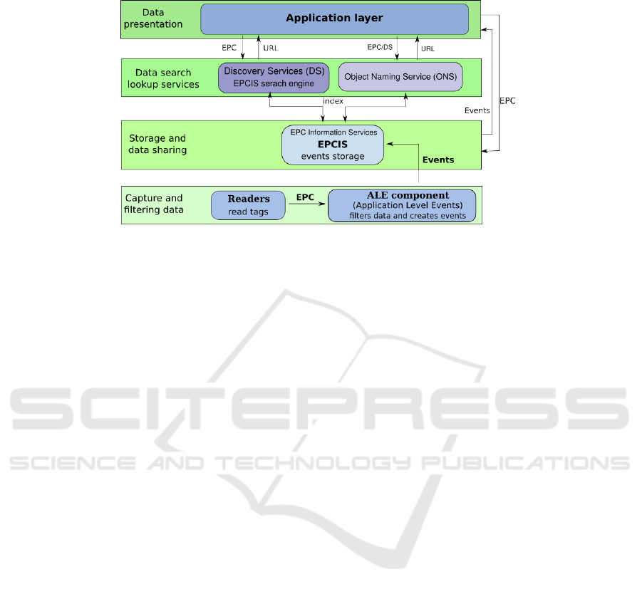
Fig. 1. EPCglobal layers.
unique Electronic Product Code (EPC). The ALE of the lower layer is in charge of edit-
ing the so called EPC events. The main goal of the upper layers will be to store and
manage efficiently these events.
As soon an event is created, it is first send to the local Electronic Product Code
Information Services (EPCIS). That component uses a persistent database to store the
events and offers a fully standardized query interface to the upper layers [2]. It also
manages master data containing necessary context for interpreting the event data.
The next layer is in charge of indexing the EPCIS in order for an application to
locate the EPCIS that stores events about a given EPC code. The first component of
this “Data Search Lookup Services” is the Object Naming Service (ONS). It aims to
provide addresses for product classes. Actually, ONS does not deal with EPC code but
solely with object class numbers. For example if company A manufactures a product
with the EPC code: urn:epc:id:sgtin:a.b.x. The ONS system will provide the EPCIS
address of the product manufacturer (company A) for the class: urn:epc:id:sgtin:a.b. It
will also provide other information like a web site address. In order to locate all the
potential sources of information for a given EPC the Discovery Services (DS) indexes
the EPCIS. Unlike web search engines that crawl the web to gather information, the
DS receives information directly by the EPCIS layer that submits information about an
event related to a given code. This design is preferred for evident access control issues.
Last the application layer may implement commercial services such as carbon foot-
print computation or counterfeit tracking.
If the components of the two lower layers are fully standardized, only the ONS is
now standardized in the upper layers. The ONS architecture mimics the Internet DNS
architecture. It is organized as a strict hierarchy. The benefit is that we can use to im-
plement the ONS, the same software as for the DNS, namely BIND.Unfortunately, the
ONS, as the DNS, is based on a single root. If this is acceptable for the DNS, as we
don’t create everyday an Internet top level domain, this is absolutely not the case for
the ONS. Some proposals exists for a Multi Root ONS [3, 11].
37

The other component responsible of the lookup services is the DS. For a given EPC
code it can deliver all EPCIS addresses dealing with that code. EPCIS enforces access
control policies. But even if the EPCIS denies the access to the event, the fact that a
given EPCIS holds a code may be a disclosure of private information. Therefore, DS
implementations must also achieve access control policies.
3 Strategies for Multi DS
As mentioned above, a realistic EPC network should have multiple DS components.
However the DS Standard is still in development by the EPCglobal Data Discovery
Joint Requirements Group and the architecture and interconnection of distributed DS
is an open question. In the paper [7], we described three alternative solutions to the
problem of several Discovery Services interconnection in order to offer a distributed
lookup architecture.
The first alternative was called “DS like a Peer”. It explained how to reference the
events stored in several EPCIS servers using a distributed hash table. Each EPCIS that
contains information on a particular EPC publishes it on the Peer2Peer cloud. A client
can then query the P2P network thanks to one front end DS server and retrieves all the
EPCIS addresses. The main drawback of this solution concerns the security and access
control policy aspects and the capability for the P2P network to prevent efficiently from
competitive intelligence.
The second solution, called “DS like a router” is based on the dynamic linking of
the EPCISs. The ONS component in the EPCglobal architecture provides the address of
the first EPCIS of the chain for a given EPC. If each EPCIS is linked for this same given
code, it is possible to retrieve the information by querying each chained EPCIS one after
the other. The main problem is to create the links between the different EPCIS. In fact,
a particular product may take a different route and could be lost unless the chaining
process is dynamic. To realize this, we proposed to use an XML rooting network. After
analysis, it appears that this solution is much to sensitive to server failure.
The last proposal called “DS indexing DS” looks simpler and more efficient to real-
ize the distributed indexing mechanism. The main aspect of this implementation is the
introduction of a new concept, the referent DS. Indeed, for each product class (i.e. EPC
without serial number) a NAPTR entry is defined in the ONS system with the code and
the address of a particular DS server. This server, that we call the referent will not only
index the EPCIS like every DS but will also index other DS servers for all the events
using a code belonging to this EPC class.
During the indexing process, each DS that receives information about a particular
EPC, queries the ONS system in order to retrieve the referent DS address. Two different
cases takes place whether the DS is the referent DS for this code or not. The DS can
easily notice he is the referent in comparing its own address with the address it received
from the ONS. If it is the referent DS, it just indexes normally the EPCIS. Otherwise,
on top of indexing the EPCIS, it publishes a new DS entry to the referent DS using the
same process as if it was an EPCIS (on the same interface and with the same protocol).
As a result, during the lookup process, the client queries the ONS system for a par-
ticular EPC class, in order to retrieve the referent DS address and queries it in turn.
38

The response may contain according to the standard several EPCIS, and/or according
to our proposal, several DS addresses. The client can then query again these new dis-
covered DS to retrieve other EPCIS addresses containing information events about that
code. When there is no more DS address to be queried, the client has collected all the
information sources that he needs to track the given object.
In this paper we give the result of the experiments conducted on our platform that
implements this third proposal (DS indexing DS).
4 The Use Case
The use case we consider to validate our multi DS strategy with a referent DS is a
simplified assembly-line production of jeans. All the usual supply chain partners are
modelled: three raw material producers, two manufactures, three wholesalers and a re-
tailer. Each partner has his own EPCIS that publishes its events to a Discovery Service.
This use case is not totally realistic. By example, we have only one retailer. In fact,
we designed it especially to stress and augment the need of communication between the
components in order to validate our multi DS schema. This section describes the events
generated in this use case by each partner.
4.1 Raw Material Producers
In the use case, we suppose that a pair of jeans is composed of denim fabric (produced
by producer 1), buttons (produced by producer 2) and zips (produced by producer 3)
3
.
If all the three producers EPCIS are located on the GREYC servers, their referent DS is
located respectively at the GREYC for producer 1, at the CERTIC for producer 2 and
at ORANGE labs for producer 3 as depicted on Figure 2.
Once made, each raw material is equipped with a new RFID tag containing a unique
EPC code. It is detected by a first reader while it enters the producer’s warehouse. The
reader publishes an event to the EPCIS with the action “ADD”. To indicate it is the first
time the EPC is detected on the supply chain, the event business step is “encoding”.
The second reader detects the good when it is loaded on a truck for delivery. The event
published has the value “OBSERVE” for action and the business step “departing”.
4.2 Manufactures
The manufacture is supposed to receive the raw material and to assemble the final prod-
uct: the jeans. For this step, there are two manufactures whose EPCISs are located in
the CERTIC, but DS for manufacture 1 is located at the GREYC.
Each manufacture has three readers. The first one tracks the arrival of raw materials.
It generates an event with action “OBSERVE” and business step “arriving”. As soon
as the jeans are made, a new RFID tag with a new EPC is created by the manufacture
RFID printer and allocated to the jeans. When the jeans get through the reader, it doesn’t
publish a simple event to the EPCIS. Indeed, in order to trace the materials origins, the
3
Not mentioning sewing thread and rivets.
39
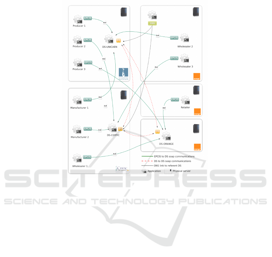
Fig. 2. IOTA deployment.
reader has to send an aggregation event encapsulating not only the jeans EPC code, but
also the EPC codes of the raw materials used for its making.
Finally, a third reader tracks goods when they leave the manufacture to go to the
wholesaler. The event has the action“OBSERVE” and the business step “departing”.
4.3 Wholesalers
The wholesaler has two readers, one located at the delivery arrival and the other one at
the delivery departure. Three wholesalers are present in this use case, the wholesaler 1
is located in the CERTIC and the wholesaler 2 and 3 are located in Orange Labs. Each
one uses a DS located on a distant site.
4.4 Retailers
The retailer is the final peer of the supply chain, thereby his part is to receive goods
from the wholesalers and to sell them to the end customers. The retailer has two readers
like wholesalers.
If the first reader tracks goods arrival as for manufacturers, the second one is rather
special. It is the last reader of the supply chain. We suppose that the tag is deactivated
40

at this step when the jeans is sold out. Therefore, the event triggered by this last reader
contains the action “DELETE” with the business step “sold”. The action “DELETE”
means that no more event concerning this EPC code will be sent in the EPC network.
To finalize the description of the use case, we must just state that the referent DS
for raw material is Ds-Unicaen and the one for jeans is DS-Certic. These two facts will
be used to compute the number of messages exchanged during the tests analyzed in
Section 6.
5 IOTA Architecture
IOTA is a platform of an EPCglobal network that realizes the whole scenario depicted
above. Each peer of this network belongs to a layer of the EPCglobal architecture as
presented on the Figure 1. In this section, we describe the peers actually installed in
IOTA and the communication between them.
IOTA is a platform gathering nine EPCIS, three DS and the ONS system distributed
over three locations (the GREYC laboratory and the CERTIC from the university of
Caen Basse-Normandie and Orange Labs Caen). Figure 2 shows the deployment of
these components by the different partners. This platform puts the EPCglobal com-
ponents in a realistic situation according to the network heterogeneity and problems
(firewalls, links speed. . . ). Only the EPCglobal upper layers are deployed in IOTA. The
components located in the capture layer (readers and ALE) are simulated using a Petri
net application described section 5.5.
5.1 General Architecture
Figure 3 depicts the IOTA architecture modules with respect to the EPCglobal frame-
work. Moreover the picture shows the components and their connections that we have
developed in order to realize and validate our multi DS implementation. If it uses, as
explained in this section, standard component implementation for EPCIS and ONS, it
uses an implementation of ESDS-1.0 specifications for the DS and an original compo-
nent: the IS2DS gateway. The lower layer is emulated with the PetriNet simulator. Last
we use a special application layer component in order to validate and test the whole
implementation; the validator.
5.2 Electronic Product Code Information System (EPCIS)
Several EPCIS implementations are currently available, like Fosstrak [4], Seres [9],
BizTalk [8], Bent System [10] or IBM [5]. In our implementation we use Fosstrak that
is an open source RFID software platform that implements the EPC Network specifi-
cations. The Fosstrak application used in IOTA contains the EPCIS repository. It offers
two interfaces: one for capture and the other for query. The Fosstrak EPCIS capture
interface uses a simple REST protocol, whereas the query interface is a full SOAP im-
plementation of the EPCglobal EPCIS interface standards [2]. Among the several query
types it allows, there is subscription. Subscription allows a client to request one EPCIS
41
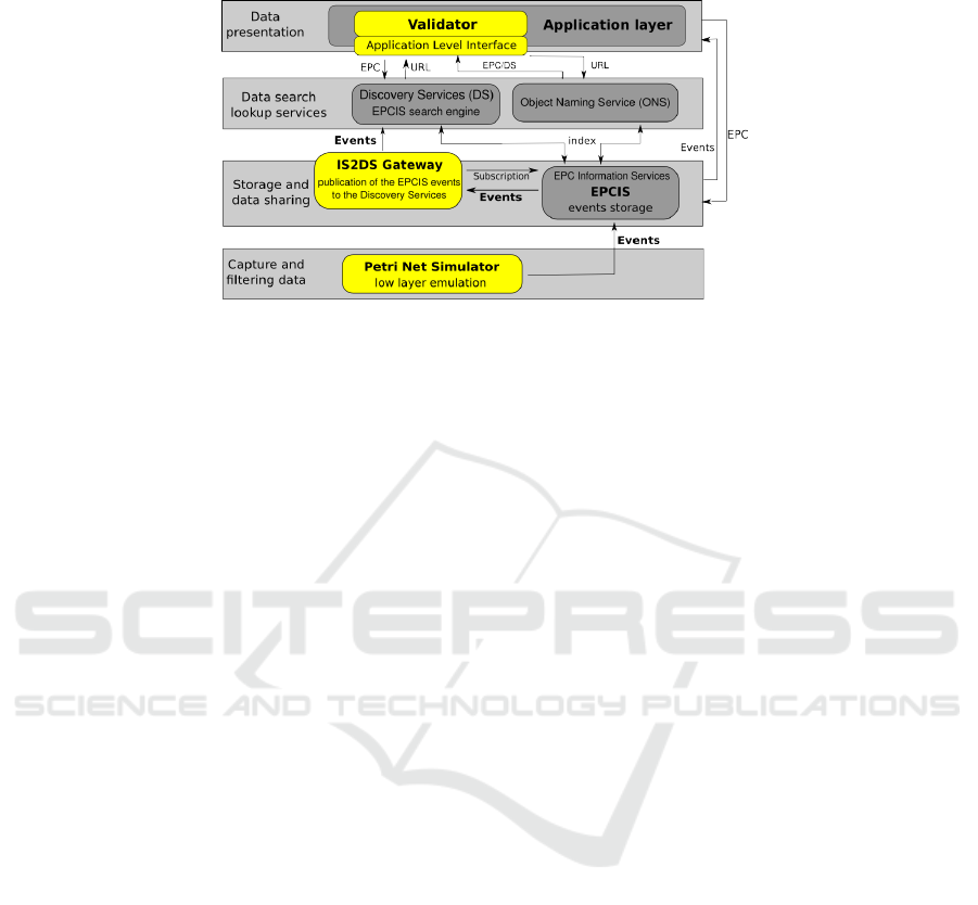
Fig. 3. IOTA functional architecture.
repository in order to retrieve periodically the last inserted filtered events. We use this
facility to connect a DS server to an EPCIS.
In order to insure the independence from EPCIS and DS standards, we developed a
new middleware component, called IS2DS Gateway, that realizes this interconnection.
It implements the EPCIS query client and subscribes to one EPCIS following a given
refresh rate. As it is, in IOTA, each IS2DS application receives minutes by minutes the
new inserted events from the EPCIS it subscribed to. This event list can be filtered by
the EPCIS owner given new parameters to the subscription such as business step, read
points. . . IS2DS has its own private database used to store in these events until they
are published to the DS server. This prevents the component to be sensitive to server
failures.
We count nine EPCIS installed in the IOTA platform. Each EPCIS has its own
IS2DS gateway connected to several DS servers. Figure 2 shows the deployment over
the three organizations. Three EPCISs (with their gateways) are installed in the GREYC
laboratory, three others in the Certic and the last three are installed in Orange Labs Caen.
5.3 Discovery Service (DS)
The Discovery Services component is not currently standardized by EPCglobal. The
instance we use in IOTA have been developed by Orange and the GREYC laboratory
partners. The core component (DS repository) is based on the EPCglobal requirements.
The capture and query interface is a SOAP implementation of the ESDS-1.0 protocol
proposed by Afilias [1]. The IS2DS application that we have just presented, uses this
same protocol to publish its events to the DS. It starts by identifying itself using the
EPCIS account created in the DS. It then, publishes its events using the eventCreate
method. In order to improve the performances, we have extend the ESDS protocol by
allowing a single SOAP message to contain several published events. As described
in Section 3, the referent DS must also index the other DS servers indexing events
concerned by the EPC codes it is referent of. The data exchange protocol used in that
case is still the same ESDS-1.0 as for the EPCIS publications. The only difference is
that DS uses a DS account instead of an EPCIS account.
42

The access control policy module is part of the DS core component. Each EPCIS
connected to a particular DS must, as a first step, create an account. In this account, the
partner can create supply chains (SC) and associate other partners. For example, partner
A creates a new SC “SC1” and associates partner B. Then partner B will be allowed to
retrieve all the indexed information inserted by partner A. Partner A can also add some
filters. For example, he can add a BizStep filter to “SC1” in order to share only the
events with the given business step value. We have currently four allowed filters on:
business step, event class, epc and event time period.
We count three DS servers in IOTA. Each site (GREYC, CERTIC and Orange Labs)
has its own instance.
5.4 Object Name Service (ONS)
The ONS architecture is based on the DNS one. The software used in IOTA to realize
the operation is Bind. Currently, we have only one local ONS instance connected to the
GS1 ONS root. The IOTA project is part of the WINGS project gathering the partners
Orange labs, GS1 France, Afnic, the LIP6 and the GREYC laboratory. This project aims
to develop a distributed ONS architecture to prevent from a centralized one like in the
DNS architecture. In this context, the IOTA platform will host in the next few months
one root ONS and an other local one.
The IOTA local ONS is currently hosted by Orange Labs on a dedicated server.
5.5 The PetriNet Simulator
Only the upper layers of the EPCglobal specifications are implemented in IOTA. There
is neither physical readers nor real ALE components. In fact, this allows to easily create
as many scenarios as we want. It is useful to create an application that is able to simulate
a lot of readers, ALE components and to publish a lot of events to as many as EPCIS
that we dream of.
In order to realize a scenario, we have developed a IOTA supply chain simulator. It
is based on a Petri net [6] where the places, transitions and tokens model respectively
warehouses, readers and objects identified by a unique EPC. The transition fire emu-
lates an ALE component, setting additional information to the event such as read point,
business step, disposition, action, timestamp, GPS localization. Then, the event is sent
to the EPCIS address specified in the transition configuration.
Some extensions have been developed in order to add constraints to the simulated
supply chain. For an “arc”, we can defined a specific number of tokens needed to ac-
tivate the next transition. It’s used for example to simulate the departure of a truck
containing several objects. Extensions for places have been also defined. The user may
specify how many products can be stored in a given place. The “EPC Generator” option
specifies that this place generates tokens with new unique EPCs. When this option is
activated, the user can specify the number of tokens and the EPC class of the generated
EPCs.
In order to realize validation tests on the IOTA platform, we need to prove that all
the generated events have been stored in the right EPCIS servers. During the object
43

transportation process, all the information concerning their evolution is stored by the
simulator. The user can specialize a place as “Event File Saver”. When a token arrives
in that particular place, its progression is stored in a log file. The user can also specify
if a place is used as “EPC Deactivator”. It simulates the fact that the product has been
sold to the final consumer and the tag has been consequently deactivated. This last
possibility solves a technical limitation. Indeed when the user wants to simulate a very
large supply chain with a lot of object and readers, for a long time, the application must
keep the travel of all the objects in its memory. The memory grows up continuously and
the simulator may fall down because of a memory leak. To prevent this situation, it is
advisable to switch on this option at each end point of the simulated supply chain.
The goal of such a simulator is also to perform measures of the servers response
times during the events capture process. Whenever an event is sent, the EPCIS server
response time is recorded by the simulator. It uses one different file by server.
5.6 The Validator
All the generated log files of the simulator may be further used by the IOTA Validator.
It is a Java application that queries the platform in order to retrieve the events stored
in the different servers and to validate their right emplacement. In order to achieve this
task, the validator takes as input the network topology, i.e. the addresses of the EPCISs,
DSs and ONSs as well as their inter-connections. It then uses the standard application
interface described in Section 5.2 and 5.3 to retrieve all the events in the different DSs
and EPCISs. Afterwards, it has only to compare the list of the collected events to the
list stored in the simulator. Finally, a report is built for each generated objects.
The report may also incorporate in the report the response times needed by the
simulator and stored in the log files. Unfortunately, as the simulator does not use directly
the DS, it is unable to monitor precisely the response time of the DS messages needed
for the indexing process.
6 Tests Results
In order to validate and test our architecture, we run several tests of events generation
with the simulator. In this section, we first count the expected number of events gener-
ated and the number of messages exchanged between the components. We then present
the number of events and the EPCISs response times measured by the simulator.
6.1 Formal Analysis of the Use Case
We count, in this section, the number of messages needed by the events recording and
indexing processes.
Each time a RFID tag is detected by a reader, one event is sent to the EPCIS. The
EPCIS will publish it to the DS using the IS2DS gateway leading to two messages: one
from the EPCIS to the IS2DS and one from the IS2DS to the DS. In case the DS is
not the referent DS for this code, a message concerning this event is forwarded to the
referent DS. These rules lead to the figures presented in table 1 for the three producers.
44

For the manufacturers, the situation is not so simple. They receive raw materials
grouped ten by ten in a truck. Thus, only one event, referencing ten EPC codes, is
generated when a reader detects ten objects. This is the case for the three different types
of raw material. After a jeans is assembled, a new tag is produced. This is recorded
through an aggregation event issued by the second reader. A last event is send to the
EPCIS when the jeans leaves the factory. This makes 2.3 events for a pair of jeans.
These events are all forwarded to the DS but a DS event must concern only a single
EPC code in the ESDS-1.0 protocol. This lead, for a final product, one event per raw
material item, plus four events because the aggregation event concerning four different
EPC codes must be split, plus the final one. This makes a total of 3 + 4 × 1 + 1 = 8
messages from the IS2DS to the DS. The number of DS to DS messages depends on
who is the referent DS for the class code as for the producers.
Table 1. Number of events generated by each peer.
Peer Number of Number of events Probability
Readers EPCIS/IS2DS IS2DS/DS DS/DS being used
Producer 1 2 2 2 0 1
Producer 2 2 2 2 2 1
Producer 3 2 2 2 2 1
Manufacturer 1 3 2.3 8 2 1/2
Manufacturer 2 3 2.3 8 6 1/2
Wholesaler 1 2 1.1 2 2 1/3
Wholesaler 2 2 1.1 2 2 1/3
Wholesaler 3 2 1.1 2 0 1/3
Retailer 2 1.1 2 2 1
The column “Probability being used” represents the probability that a given object
will pass through this supply chain peer. As the simulator uses an equiprobabilty law to
decide which manufacturer makes a jeans, the probability is 1/2.
The wholesalers and the retailer each receive the jeans ten by ten detected by the
first reader and detect single jeans at the second reader. This triggers a total of eleven
events to the IS2DS for a group of ten jeans. Then, on the average, we have 1.1 event.
As the referent DS for jeans is the DS of the EPCIS of wholesaler 3, no DS to DS
message is generated. On the contrary, two DS to DS messages are generated by the DS
of the wholesaler 1 and 2. The probability of using a given wholesaler out the three is
1/3 as their use is equiprobale.
We can now compute the average number of messages send when an object pass
through the whole supply chain. We have just to multiply the number of each kind of
messages at each peer, by the probability it passed through that peer. This leads to the
following figures: 10.5 EPCIS/IS2DS, 18 IS2DS/DS and 11.33 DS/DS messages.
6.2 Measures
We run two kinds of benchmarks. The first kind was run in regular condition: no incident
on the servers or on the network. The second one aim to test the robustness on the
45

platform to server or network failures and study how it recovers from these exceptional
situations.
Benchmarks have been run for different durations. For each test, we record the
complete route of an object to the retailer. When it ends, no object with active RFID
tags exists. Thus we know precisely how many final object product (pair of jeans) are
involved. We used the validator to collect the statistics and check the integrity of the
information system.
Results are presented in table 2 for regular conditions and 3 with failures and re-
cover. The Petri net simulator was always set to fire a transition every 100 ms. This
triggers the construction of a new event and its forwarding to an EPCIS. The actual
time interval between two event generation includes that overhead.
Table 2. Parameters of the tests with different durations.
# Duration Product Publication Number of messages
(min) qty freq (ms) EPCIS/IS2DS IS2DS/DS DS/DS
1 30 776 220 8 148 13 968 8 795
4 60 1 648 208 17 304 29 660 18 670
5 185 4 846 218 50 883 87 230 54 920
6 1200 33 222 206 348 831 59 800 37 650
7 5105 138 000 211 1 449 000 2 484 000 1 564 000
The goal of these first tests is to demonstrate the reliability of the IOTA’s platform
using simulations stressful for the network. The tests are conclusive after a four days
duration. The figures evolution is smooth: the publication frequency is stable along the
different tests. We are confidant in the longterm behavior of the platform, though we
should run longer tests.
The goal of the second tests series was to show that our components is failure proof.
To show this, we have run a thirty minutes tests with three gateways out of order and
a second one with a Discovery Services component down. After the restart of these
components, the system returned to a regular state after only two minutes. Furthermore,
the best test have been done during the longterm test # 7. In fact, a firewall rule have
been inadvertently deleted during this test and the route between a IS2DS gateway and
its DS was broken for twenty eigth hours. During this time the gateway had 200 000
events waiting for publication. It took roughly 90 minutes the gateway to publish the
delayed events to the DS.
To recover from a DS failure, the IS2DS does not try to send all the awaiting events
in one bunch. In order to not stress the DS, events are sent grouped by thousands. This
limitation allows a graceful recover.
The figure 4 shows the response times of each EPCISs measured by the simulator
using box plots
4
. Box plots represent the quartiles of the distribution and the mean
value. 50 % of the population are inside the box. The two whiskers go to the minimum
and to the maximum values excluding outliers. Outliers are represented with white cir-
cles and triangles.
4
Also known as box-and-whisker diagram.
46
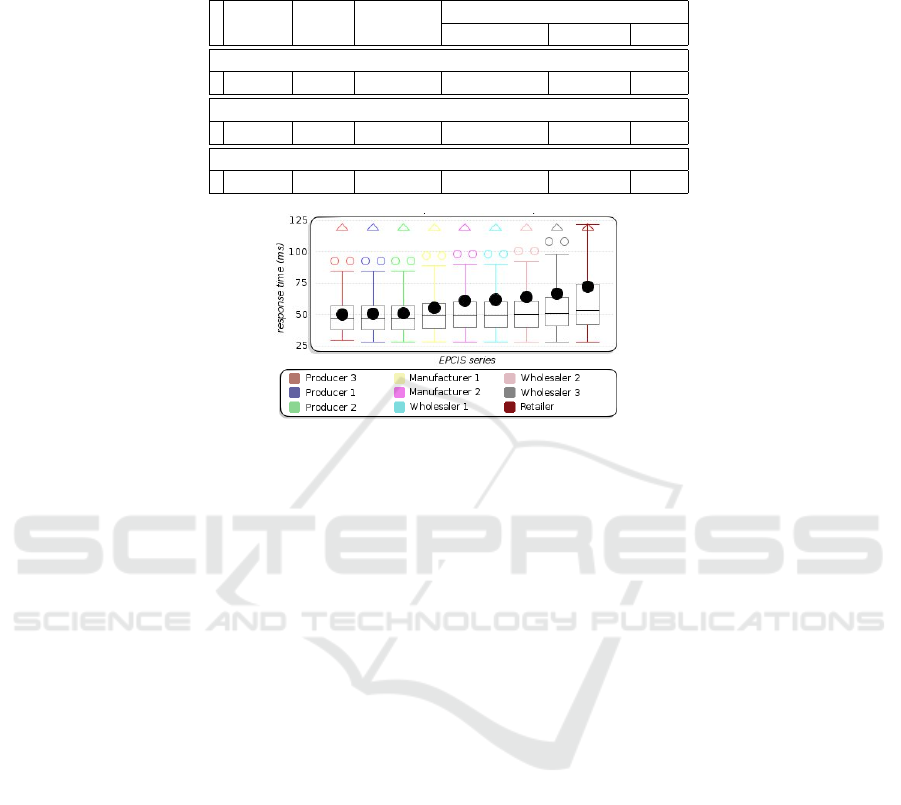
Table 3. Parameters of the tests with different conditions.
# Duration Product Publication Number of events
(min) qty freq (ms) EPCIS/IS2DS IS2DS/DS DS/DS
Test with regular conditions (no incident)
1 30 776 220 8 148 13 968 8 795
Test with three IS2DS gateways down
2 30 1 030 166 10 815 18 540 11 673
Test with one DS down
3 30 983 174 10 321 17 694 11 141
Fig. 4. EPCISs response times.
50 % of the messages take than 50 ms for a round trip. Note that the mean is always
above the median value and even for five EPCIS, it is roughly equal to the third quartile.
This shows many large outliers values. Large response time values happen each time an
EPCIS does not respond immediately at once. In such a situation, the simulator waits
for three minutes before to attempt a retry.
The average round trip time increases from left to right on Figure 4. As a matter
of fact, the EPCIS are ordered on the graph in increasing number of network router
between the EPCIS and the simulator. It appears that an EPCIS will not respond imme-
diately more likely if there are more routers to cross. In case of non immediate response,
the retry time out penalizes heavily the response time.
7 Conclusions
We have presented the implementation of distributed Discovery Services working over
a real network. Our solution is functional, furthermore, it does not use much overhead
resources.
The platform uses a standard implementation for the EPCIS (Fosstrak) and the ONS
(Bind). We have developed two components for DS and IS2DS. The capture lower layer
is emulated by a Petri net simulator. Finally, we have developed a component, taking
place in the top level application layer, used for validation and benchmarking.
Regarding the protocols used, we have enhanced the ESDS-1.0 protocol in order to
minimize the number of messages. We have simply allowed a message to hold multiple
events on the same or different EPC codes. A further enhancement would be to accept
a DS event to refer several different EPC codes.
47

Access control policies enforcement for a distributed lookup services is our next
challenge.
References
1. Afilias. Afilias discovery services. http://www.afilias.info/.
2. EPCGlobal. Epcis - epc information services standard. http://www.epcglobalinc.org/stan-
dards/epcis/epcis 1 0 1-standard-20070921.pdf, 2007.
3. Sergei Evdokimov, Benjamin Fabian, and Oliver G
¨
unther. Multipolarity for the object nam-
ing service. In Proceedings of the First International Conference, The Internet of Things,
IOT 2008, volume 4952 of Lecture Notes in Computer Science, pages 1–18, Zurich, Switzer-
land, march 2008. Springer.
4. Fosstrak. Free and open source software for track and trace. http://www.fosstrak.org.
5. IBM. Infosphere traceability server. http://www-01.ibm.com/software/data/infosphere/
traceability-server/.
6. Ekkart Kindler and Michael Weber. The petri net kernel: An infrastructure for building petri
net tools. Software Tools for Technology Transfer (STTT, 3:486–497, 1999.
7. J. Le Moulec, J. Madelaine, and Bedini I. Discovery services interconnection. In Pro-
ceedings of the 3rd International Workshop on RFID Technology - Concepts, Applications,
Challenges (IWRT 2009), pages 59–68, Milan, Italy, mai 2009. INSTICC Press, Portugal.
8. Microsoft. Microsoft biztalk rfid. http://www.microsoft.com/biztalk/.
9. Seres. Seres. http://www.seres.fr/.
10. Bent System. Rfid epcis savant. http://www.bentsystems.com/.
11. WINGS. Wings anr project. http://www.wings-project.fr/.
48
