
FEATURE ASSEMBLY MODELLING
A New Technique for Modelling Variable Software
Lamia Abo Zaid, Frederic Kleinermann and Olga de Troyer
Vrije Universiteit Brussel (VUB), Pleinlaan 2, 1050 Brussel, Belgium
Keywords: Feature Analysis, Software Variability, Modelling Variability, Feature Models, Domain Analysis.
Abstract: For over two decades feature modelling techniques are used in the software research community for domain
analysis and modelling of variable software. However, feature modelling has not found its way to the
industry. In this paper we present a new feature modelling technique, developed in the context of a new
approach called Feature Assembly, which overcomes some of the limitations of the current feature
modelling techniques. We use a multi-perspective approach to deal with the complexity of large systems,
we provide a simpler and easier to use modelling language, and last but not least we separated the variability
specifications from the feature specifications which allow reusing features in different contexts.
1 INTRODUCTION
Variable software namely software product lines
(Bosch, 2000) are gaining more and more popularity
due to its capability of providing higher productivity
through putting the fundamental base for developing
multiple closely related but different products. To
be able to profit maximally from the benefits of
variable software, while keeping the development
process under control, feature-oriented analysis
should be adopted to effectively identify and
characterize the product line capabilities and
functionalities at an early stage. In feature-oriented
analysis, features are abstractions that different
stakeholders can understand. Stakeholders usually
speak of product characteristics i.e. in terms of the
features the product has or delivers (Kang et al.,
2002).
Feature oriented domain analysis (FODA) (Kang
et al., 1990) was first introduced in the 1990 and
since then it has become an appealing technique to
the software research community for modelling
variable software. It was applied to several case
studies and many extensions to the original
technique have been defined. However, these feature
modelling techniques have not gained much
popularity outside the research community. Several
explanations can be given for this. Firstly, there are
many different “dialects” of feature modelling
techniques (such as (Kang et al., 1998), (Griss et al.,
1998), and (Czarnecki et al., 2005)), each focusing
on different issues; there is no commonly accepted
model (Nestor et al., 2008). Secondly, feature
models do not scale well, mainly because they lack
abstraction mechanisms. This makes them difficult
to use in projects with a large number of features
(Bosch, 2005). Thirdly, little guidelines or methods
exist on how to use the modelling technique. This
often results in feature models with little added
value or of discussable quality.
To overcome these limitations companies define
their own notations and techniques to represent and
implement variability. Examples are Bosch
(MacGregor, 2002), Philips Medical Systems (Jaring
et al., 2004) and Nokia (Maccari and Heie, 2005).
Yet the proposed notations are tailored to each
company’s specific needs for modelling variability
in their product line. In (MacGregor, 2002) and
(Jaring et al., 2004), a hierarchical structure of
feature was adopted (similar to feature models) but
new feature types were introduced; i.e. how a feature
relates to variability. While Maccari and Heie (2005)
were more concerned with feature interaction and
scalability issues, therefore, for documentation
purposes, they adopted a separation of concern
approach for devising higher level features.
In this paper we present a new feature modelling
technique, called Feature Assembly Modelling
(FAM). The presented modelling technique is
innovative from different perspectives. FAM
separates the information on variability (i.e. how
features are used to come to variability) from the
29
Abo Zaid L., Kleinermann F. and de Troyer O. (2010).
FEATURE ASSEMBLY MODELLING - A New Technique for Modelling Variable Software.
In Proceedings of the 5th International Conference on Software and Data Technologies, pages 29-35
DOI: 10.5220/0003005600290035
Copyright
c
SciTePress

features themselves. This yields more flexibility and
allows the reuse of these features in other contexts
and even in other software. Next, it is well known
that focusing on one aspect at the time helps to deal
with complexity (separation of concerns paradigm).
Therefore, in FAM, the software is modelled from
different perspectives, which provides an abstraction
mechanism. This provides the benefit of increasing
the scalability Furthermore, we have reduced the
number of modelling primitives to simplify and ease
the modelling process.
This paper is organized as follows, in section 2,
we review existing feature modelling techniques. In
section 3, we discuss the limitations of the
mainstream feature modelling techniques. In section
4, we explain our new feature modelling technique,
Feature Assembly. Section 5 provides an example
that illustrates the approach and its benefits. Section
6 provides a conclusion and future work.
2 MAINSTREAM FEATURE
MODELLING TECHNIQUES
Over the past few years, several variability
modelling techniques have been developed that aim
supporting variability representation and modelling.
For the purpose of this paper we restrict ourselves to
the modelling methods (techniques) that model only
variability, we refer the reader to (Sinnema and
Deelstra, 2007) for a complete classification.
2.1 Methods Extending FODA
Feature Oriented Domain Analysis (FODA) defines
a (graphical) variability modelling language,
commonly called feature models (Kang et al., 1990).
Several extensions to FODA have been defined to
compensate for some of its ambiguities and to
introduce new concepts and semantics to extend
FODA’s expressiveness. Yet, all keep the
hierarchical structure originally used in FODA. For
example, FORM (Kang et al., 1998) extends FODA
by adding a domain architecture level which
categorizes features to belong to one of four layers:
capabilities, operating environments, domain
technologies, and implementation. FeatureRSEB
(Griss et al., 1998) aims at integrating feature
modelling with the Reuse-Driven Software
Engineering Business (RSEB). Starting from UML
use case models to identify features, FeatureRSEB
classifies features to optional, mandatory (similar to
FODA) and variant. Variant is used to indicate
alternative features and also any set of features in
which selectivity is allowed. In FeatureRSEB, the
notation of FODA was modified to add the concept
of vp-features which represent variation points.
PLUSS (Eriksson et al., 2005), the Product Line Use
case modelling for Systems and Software
engineering, introduced the notation of multiple
adapter to overcome the limitation of not being able
to specify the at-least-one-out-of-many relation in
FODA. PLUSS also renamed alternative features to
single adaptor features following the same naming
scheme. CBFM (Czarnecki, and Kim, 2005),
Cardinality Based Feature Models, defines for each
feature one of two types of cardinality: clone
cardinality and group cardinality. A feature clone
cardinality is an interval of the form [m..n]. Where
m and n are integers that denote how many clones of
the feature (with its entire subtree) can be included
in a specified configuration. A group cardinality is
an interval of the form [m..n], where m and n are
integers that denote how many features of the group
are allowed to be selected in a certain configuration.
In addition, the notation of feature attribute was
defined. A feature attribute indicates a property or
parameter of that feature.
2.2 UML Variability Profiles
UML (unified modelling language) is a well
accepted modelling language for modelling software
applications. Several proposals extended UML to
support feature modelling. In (Clauss, 2001), two
stereotypes are introduced to model variability,
namely: <<variationpoint>> and <<variant>>.
These stereotypes can be applied on any UML
element that holds variability. Two stereotypes are
used to model dependencies <<requires>> and
<<excludes>>. In (Ziadi et al., 2003), a UML
Profile which contains stereotypes, tagged values
and constraints and which extends the UML meta-
model is defined to model and represent variability.
These stereotypes are applied only to UML class
diagrams and sequence diagrams. The stereotype
<<optional>>, <<variation>>, and <<variant>>
are used to indicate optional UML elements,
variation points and variants respectively. In
(Gomaa, 2005) another attempt was made to
combine UML and feature models. UML stereotypes
are used to represent the different types of (variable)
features that exist in FODA. To increase the
expressiveness of the model some additional feature
types were added. The stereotypes defined for
feature types are: <<optional feature>>,
<<parameterized feature>>, <<common
ICSOFT 2010 - 5th International Conference on Software and Data Technologies
30

feature>>, <<default feature>>, and <<alternative
feature>>. Feature groups map the OR/alternative
nodes and are defined using <<feature group>>.
2.3 Other Modelling Methods
Some other attempts to improve the modelling of
variable software were made. In (Asikainen et al.,
2007), a domain ontology for modelling variability
in software product families was defined. The
modelling concepts include components and features
with compositional structures and attributes, the
interfaces of components and connections between
them, in addition to constraints. In COVAMOF
(Sinnema et al., 2004), a feature based Variability
View (CVV) is used to model variability. It consists
of the Variation Point View, which captures
variability through variation points and variants that
are attached to the features of the software, and the
Dependency View which holds the interrelations
between the different variation points and variants.
3 LIMITATIONS OF
MAINSTREAM FEATURE
MODELLING TECHNIQUES
As mentioned in the introduction of this paper and
reflected in section 2, the notion of feature is very
convenient for characterizing (variable) software.
Feature models relate features by means of a
AND/OR hierarchical structure, describing how
features are broken up into more finer-grained ones.
For small applications this works fine, as features
are perceived quite easily and often represent the
main system capabilities and components. Yet for
practical cases there is usually great doubt in how to
apply the feature modelling technique. First, because
there are many alternatives to the original FODA,
which all differ in their semantics as well as their
notations and it is not obvious for companies to
select the one most appropriate This has triggered
the need for a comparative survey on feature-based
notations (Djebbi and Salinesi, 2006), to help
companies decide which technique better suits their
needs). Next, these techniques are not associated
with a concrete methodology or guidelines that
designers can use in order to create their feature
models. This makes the modelling process a difficult
task. In addition, FODA and subsequent feature
modelling techniques lack explicit abstraction
mechanisms. There is no guidance on the required
level of granularity for the feature decomposition
process. The original FODA defined four categories
to which features of the system belong (Kang et al.,
1990): operating environments, capabilities, domain
technology, and implementation techniques.
However, we see this categorization process as very
fragile and impractical. In reality, a feature may
have many faces which make categorizing features a
difficult task.
Furthermore, feature modelling techniques miss
linking their notations of features with the notations
of variation point and variant which is preferred
among stakeholders interested merely in variability
(Bosch, 2000). UML based variability modelling
tried to address this issue. Yet UML variability
modelling techniques speak the language of class
rather than feature.
As already mentioned, not only do feature
modelling techniques lack an associated modelling
method, but also the main modelling concept, being
feature, is not rigorously defined. Even worse, there
are many different “definitions” that exist. Actually
each technique is using its own definition. We list
some of these definitions:
1. A feature is a prominent or distinctive user-
visible aspect, quality, or characteristic of a
software system or systems (Kang et al., 1990)
2. A feature is a logical unit of behaviour specified
by a set of functional and non-functional
requirements (Bosch, 2000)
3. A feature is an increment in program
functionality (Batory, 2005)
It can be seen from these different definitions
that features can be considered from different
perspectives. While the first definition takes the
user’s perspective for defining what a feature is, the
second takes the requirements perspective for
defining what a feature is, and the third takes the
functional perspective for defining what a feature is.
This observation has led us to base our feature
assembly approach (which will be introduced in
section 4) on multi perspectives as an abstraction
mechanism. The observation that feature modelling
is not used by companies (probably due to the
limitations of feature modelling techniques (see
above)) but confronted with the many challenges
related to variable software that companies face
1
has
triggered the need to revise the feature modelling
technique. The following requirements were
formulated:
1) A rigorous methodology for feature modelling
1
This research is carried out in the context of VariBru project in
which the needs and challenges regarding variability of
industrial companies in Brussels are investigated.
FEATURE ASSEMBLY MODELLING - A New Technique for Modelling Variable Software
31
is needed.
2) Abstraction mechanisms to better deal with
complex and large systems are necessary.
3) Support for feature reuse must be provided.
The next section will explain our feature
assembly modelling technique. Note that this
technique is part of an overall Feature Assembly
approach, which supports the reuse of features
between different software.
4 FEATURE ASSEMBLY
MODELING TECHNIQUE
Feature Assembly Modelling is a feature-oriented
modelling technique intended to model the
variability aspects of complex variable software
during analysis and/or design. It does so by using
different perspectives, where each perspective
represents a single viewpoint. Trying to deal with all
the viewpoints at the same point is difficult and will
usually result in badly structured designs. A more
scalable approach is to identify the different
perspectives needed and model the required
capabilities of the software and deal with one
perspective at a time. Furthermore, within a single
perspective; we represent how features are
composed and related (assembled). The model is
based on a few simple modelling concepts that allow
modelling features, variability relations, and feature
dependencies. We will discuss the approach into
more detail in the following sections.
4.1 Multi-perspective Approach
A perspective is used to model the variability of the
software from a certain viewpoint. The perspectives
used for the modelling can be freely chosen
depending on the application under consideration.
To help the analysis, a (variable and extendible) set
of possible perspectives have been proposed, such as
a System perspective, which provides a bird’s eye
view on the system; a Users perspective, which
identifies the different categories of users who could
be using the software; a Functional perspective,
which represents features responsible for
functionality; a User Interface perspective, which
defines the basic features of the software’s user
interface. This set can be further extended based on
the needs of the application under consideration. For
example, a Hardware perspective may be considered
for embedded applications; or a Task perspective
could be used for modelling a task-based application
and a Localization perspective for software that
needs to be localized for different markets. If a
perspective is not required for a certain application it
can be omitted. The exact definition of the concept
of a feature depends on the perspective. In general, a
feature can be considered as a physical or logical
unit that acts as a building block that fulfils the
capabilities of the perspective that holds it.
The idea of using perspectives or viewpoints is
not new in software development; it was first
introduced in (Finkelstein et al., 1992) to show how
adopting perspectives helps in efficient modelling of
the software system. In (Graham, 1996), and
(Woods, 2004) abstraction via viewpoints was
introduced for software architecture modelling.
4.2 Basic Modelling Primitives
To model the features of one perspective, we have
revised the existing feature modelling techniques
and came up with a new and simplified technique. In
feature models, the featured type is used to express
how a feature contributes to variability. However,
because a feature can contribute differently to
variability in different situations, we separated how
the feature contributes to variability from its
definition. Therefore, we only consider two types of
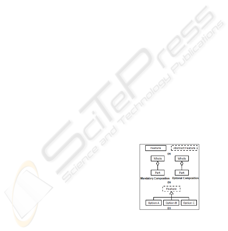
features: Feature and Abstract Feature. A Feature
represents a concrete logical or physical unit or
characteristic of the system. An Abstract Feature is
a feature which is not concrete; rather it is a
generalization of more specific features (concrete or
abstract ones). Figure 1.a shows the notations used
to represent both feature types.
Figure 1: FAM Notation (a) Feature types, (b)
Composition relation, (c) Generalization/ Specification
relation.
How the features are assembled together to
model the system is specified via feature relations.
We define two types of feature relations:
composition relation and generalization/
ICSOFT 2010 - 5th International Conference on Software and Data Technologies
32
specification relation. The composition relation is
used to express the whole-part relation; i.e. a feature
is composed of one or more fine-grained features.
The composition can be mandatory or optional.
Figure 1.b shows the composition relation notation.
The generalization/ specification relation is used
only in combination with abstract features and allow
specifying possible (concrete or abstract) Option
Features of an abstract feature. Figure 1.c shows the
generalization/ specification notation. In terms of
variability, an abstract feature represents a variation
point. Its available option features represent
variants. The number of option features allowed to
be selected in a certain product is expressed via a
cardinality constraint. The cardinality constraint
specifies the minimum and maximum number of
features allowed to be selected. A dash is used to
specify “any”.
4.3 Feature Dependencies
Feature Dependencies specifies how a feature may
affect other feature(s). Dependencies can be
expressed between features from a single
perspective (i.e. inter-perspective) as well as
between features from different perspectives (i.e.
intra-perspective). Expressing dependencies between
features of different perspectives also links the
different perspectives. In our previous work (Abo
Zaid et al., 2009), we defined the following set of
keywords that denote feature dependencies:
excludes, incompatible, same, extends, impacts,
includes, requires, uses. In FAM the same set still
holds. Additionally, features from different
perspectives can be combined with AND and
OR. The form is: <virtual_feature> <dependency>
<virtual_feature>, where <virtual feature> is one or
more features connected with AND/OR, and
<dependency> is a feature dependency keyword. In
intra-perspective dependencies, a feature must be
identified by both the name of its perspective and its
feature name as will be shown in section 5.
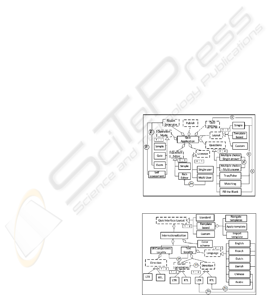
5 EXAMPLE
In this section we provide an example to
demonstrate the feature assembly modelling
technique. Figure 2 shows the System perspective of
a Quiz Product Line (QPL) application, a variable
software for making Quizzes. It is mandatory
composed of a set of features namely: Questions,
Layout, License, Report Generator, Operation Mode
and Question Editor. In addition, the following
features are optional part of the quiz application:
Quiz Utilities, and Publish. The Questions feature is
an abstract feature (i.e. variation point), which has
five concrete option features (i.e. variants). In any
valid product at least two and at most four of these
options should exist; this is specified by the
cardinality 2:4. On the other hand, the abstract
feature Operation Mode has four option features; at
least one has to be selected, no upper limit is
defined, this is indicated by the cardinality 1:-.
Figure 2 also shows some features part of the quiz
application (Quiz Utilities and Publish) for which no
details are specified (yet). This is an important
aspect of FAM; it allows identifying abstract
features or variation points while the concrete
options (or variants) may not yet been known. This
allows adopting an incremental design approach.
Figure 2 also shows the inter-perspective
dependencies, for example there is a requires
dependency between Exam and Report Generator.
Figure 3 shows features of the User interface
perspective and their dependencies. Furthermore, the
perspectives shown in figures 2 and 3 hold intra-
perspective dependencies, shown in listing 1(User
perspective was omitted due to space limitation, also
only subset of the models are shown).
Figure 2: QPL system perspective.
Figure 3: QPL user interface perspective.
FEATURE ASSEMBLY MODELLING - A New Technique for Modelling Variable Software
33

Users.Higher_Education AND
User_Interface.Template_Based requires
System.Publish
System.Layout impacts
User_Interface.Quiz_Interface_Layout
User_Interface.Dutch AND
User.Cooperate_Bussiness requires
System.Custom
Listing 1: QPL sample Intra-perspective dependencies.
6 CONCLUSIONS AND FUTURE
WORK
In this paper we have presented a new multi-
perspective feature-oriented technique for modelling
variability, called Feature Assembly Modelling
(FAM). FAM tried to address some of the
limitations of mainstream feature modelling
techniques such as lack of abstraction mechanisms,
weak support (if any) for complex and large
software, and the complexity of the technique for
non-experience modellers. The modelling technique
is part of the Feature Assembly approach, which also
addressed some of the challenges that were not
perceived by FODA such as the need for reusing
feature specifications across different applications.
FAM uses a multi-perspective approach for
modelling the variability. Perspectives act as
abstraction mechanism enabling better separation of
concerns when modelling software. The different
perspectives are interconnected via feature
dependencies; this provides a more complete picture
of the system modelled. In addition, we have
reduced the number of modelling primitives used
separated variability specification from the feature
definition. This will allow reusing features for
different software systems (not shown in this paper).
The next step in the research is to apply FAM to
an industrial case to validate its usability and
expressivity. We are also working on a method to
collect and store features in a so-called Feature Pool
and provide mechanisms to select them for reuse in
other software (the Feature Assembly approach).
REFERENCES
Abo Zaid, L., Kleinermann, F., De Troyer, O. (2009).
Applying semantic web technology to feature
modeling. SAC 2009: 1252-1256.
Asikainen, T., Männistö, T., and Soininen, T. (2007).
Kumbang: A Domain Ontology for Modelling
Variability in Software Product Families. Advanced
Engineering Informatics, 21(1), pp. 23-40.
Batory, D. (2005). Feature models, grammars, and
propositional formulas. In: Obbink, H., Pohl, K. (eds.)
SPLC 2005. LNCS, vol. 3714.
Bosch, J. (2005). Software Product Families in Nokia. In:
9th International Conference SPLC 2005.
Bosch, J. (2000). Design and Use of Software
Architectures: Adapting and Evolving a Product-Line
Approach. Addison-Wesley. ISBN: 0-201-67494-7.
Clauss ,M. (2001). Generic Modeling using UML
extensions for variability. In Workshop on Domain-
specific Visual Languages, OOPSLA 2001, pp. 11-18.
Czarnecki, K. and Kim, C. H. P.(2005). Cardinality-Based
Feature Modeling and Constraints. In OOPSLA’05
International Workshop on Software Factories.
Djebbi, O., Salinesi, C. (2006). Criteria for Comparing
Requirements Variability Modeling Notations for
Product Lines. In: Comparative Evaluation in
Requirements Engineering, CERE '06. pp. 20-35.
Eriksson, M., Börstler, J., and Borg, K. (2005). The
PLUSS Approach - Domain Modeling with Features,
Use Cases and Use Case Realizations. In Obbink and
Pohl (eds). SPLC 2005, LNCS 3714, pp. 33–44.
Finkelstein, A., Kramer, J., Nuseibeh, B., Finkelstein, L.,
Goedicke, M. (1992). Viewpoints: A Framework for
Integrating Multiple Perspectives in System
Development. Intl. J. of Software Engineering and
Knowledge Engineering 2(1), 31–57.
Gomaa, H., (2005). Designing Software Product Lines
with UML: From Use Cases to Pattern-Based
Software Architectures, Addison-Wesley
Graham, T.C.N. (1996). Viewpoints Supporting the
Development of Interactive Software. In: Proceedings
of Viewpoints 96: International Workshop on Multiple
Perspectives in Software Development, pp. 263-267.
Griss, M., Favaro, J., and d’Alessandro, M. (1998).
Integrating Feature Modeling with the RSEB. In: Fifth
International Conference on Software Reuse, pp. 76–
85.
Jaring, M., Krikhaar, R. L., and Bosch, J. (2004).
Representing variability in a family of MRI scanners.
Software—Practice & Experience. Volume 34 . Issue
1. pp: 69 – 100.
Kang, K., Cohen, S., Hess, J., Novak, W., and Peterson, A.
(1990). Feature-oriented domain analysis (FODA)
feasibility study. Technical Report CMU/SEI-90-TR-
021. Software Engineering Institute.
Kang, K., Kim, S., Lee, J., Kim, K., Shin, E., and Huh, M.
(1998). FORM: A Feature-Oriented Reuse Method
with Domain-Specific Reference Architectures. In: J.
Annals of Software Engineering. vol. 5, pp. 143-168.
Kang, K. C., Lee, J. and Donohoe., P. (2002). Feature-
Oriented Product Line Engineering. IEEE Software.
vol. 19, no. 4, pp. 58-65.
Maccari, A., and Heie, A. (2005): Managing infinite
variability in mobile terminal software. Softw., Pract.
Exper. 35(6): pp 513-537.
MacGregor, J. (2002) Bosch Experience Report,Technical
report IST-2001-34438.
ICSOFT 2010 - 5th International Conference on Software and Data Technologies
34

Nestor, D., Thiel, S., Botterweck, G., Cawley, C., and
Healy, P. (2008). Applying visualisation techniques in
software product lines. SOFTVIS 2008. pp. 175-184.
Sinnema M., and Deelstra, S. (2007): Classifying
Variability Modeling Techniques. Journal on
Information and Software Technology. Volume 49,
Issue 7, pp. 717-739.
Sinnema, M., Deelstra, S., Nijhuis, J., Bosch, J. (2004).
COVAMOF: A Framework for Modeling Variability
in Software Product Families. SPLC 2004.pp. 197-213
Woods, E. (2004). Experiences Using Viewpoints for
Information Systems Architecture: An Industrial
Experience Report. EWSA: 182-193
Ziadi, T., Hélouët, L., and Jézéquel ,J. M. (2003). Towards
a UML Profile for Software Product Lines, In
Software Product-Family Engineering, 5th
International Workshop. Pp. 129-139.
FEATURE ASSEMBLY MODELLING - A New Technique for Modelling Variable Software
35
