
A GENERIC FRAMEWORK FOR DISTRIBUTED
COMPONENT-BASED SOFTWARE SYSTEMS DEPLOYMENT
Case Study and Tool Description
Mariam Dibo and Noureddine Belkhatir
Laboratoire d’Informatique de Grenoble, 681, Rue de la Passerelle, BP 72, 38402 St Martin d'Hères, France
Keywords: Deployment, Meta model, Model, Software component, MDA.
Abstract: The life cycle of distributed component-based software systems raises a new challenge due to architecture
and environment complexity. Hence there is an increased need for new techniques and tools to manage
these systems mainly their deployment. Following our previous publications (Dibo and Belkhatir, 2010b,
Dibo and Belkhatir, 2010a, Dibo and Belkhatir, 2009). This paper deals with software deployment and
focuses first on UDeploy (Unified Deployment architecture), a generic framework for distributed
component based software system. Secondly, we present a deployment case study to illustrate our approach.
1 INTRODUCTION
Component-based software approach (Szyperski et
al., 2002) is intended to improve the reuse of
component enabling the development of new
applications by assembling pre-existing components.
A software component can be deployed
independently and may to be composed by third
parties (Szyperski et al., 2002).
Nowadays, the component approach and
distribution make deployment a very complex
process. Many deployment tools exist, we identified
three types of systems: 1) those developed by the
industry and integrated into a middleware
environment like EJB (Dochez, 2009), CCM (OMG,
2006a) and .Net (Troelsen, 2008a, Troelsen, 2008b);
2) those projected by the OMG (industry) (OMG,
2006b) (Edwards et al., 2004) based on more generic
models and; 3) the more formal systems projected
by academic works in current component models
like Open Service Gateway Initiative (OSGI)
(Alliance, 2005), Web Services (Gustavo et al.,
2004), SOFA (Bures et al., 2006), Architecture
Description Languages (ADL) (Clements, 1996) and
UML 2.0 (OMG, 2007).
Generally, deployment tools are often built in an
ad hoc way; i.e. specific to a technology or to an
architecture and covering partially the deployment
life cycle (using generally the installation scripts).
Hence, deployment is seen as the post develop-
ment activities that make software usable. It covers
the description of the application to deploy, the
description of the physical infrastructure, the
description of the deployment strategies, the
planning activities and the plan execution.
The deployment issue deals with aspects as
diverse as satisfying software and hardware
constraints of the components with regard to the
resources of the machines that support them, the
resolution of inter-component dependency, the
installation and “instantiation” of components via
the middleware and the container, the
interconnection of components, their activation and
the management of dynamic updates. Thus the
challenge is to develop a generic framework
encompassing a specific approach and supporting
the whole deployment process. (Dibo and Belkhatir,
2010a) presents this approach based on MDA
approach (OMG, 2005).
This paper focuses on the implementation part
fulfilled by UDeploy and the presentation of a case
study to illustrate our approach. The rest of this
paper is organized as follows: part 2 presents the
architecture of our deployment tool. Part 3 presents a
case study. Finally in part 4, we present the
perspectives of this work.
2 UDEPLOY ARCHITECTURE
Figure 1 briefly presents the UDeploy architecture
which manages the deployment process. The process
159
Dibo M. and Belkhatir N. (2010).
A GENERIC FRAMEWORK FOR DISTRIBUTED COMPONENTS-BASED SOFTWARE SYSTEMS DEPLOYMENT - Case Study and Tool Description.
In Proceedings of the Fifth International Conference on Evaluation of Novel Approaches to Software Engineering, pages 159-167
DOI: 10.5220/0003001301590167
Copyright
c
SciTePress
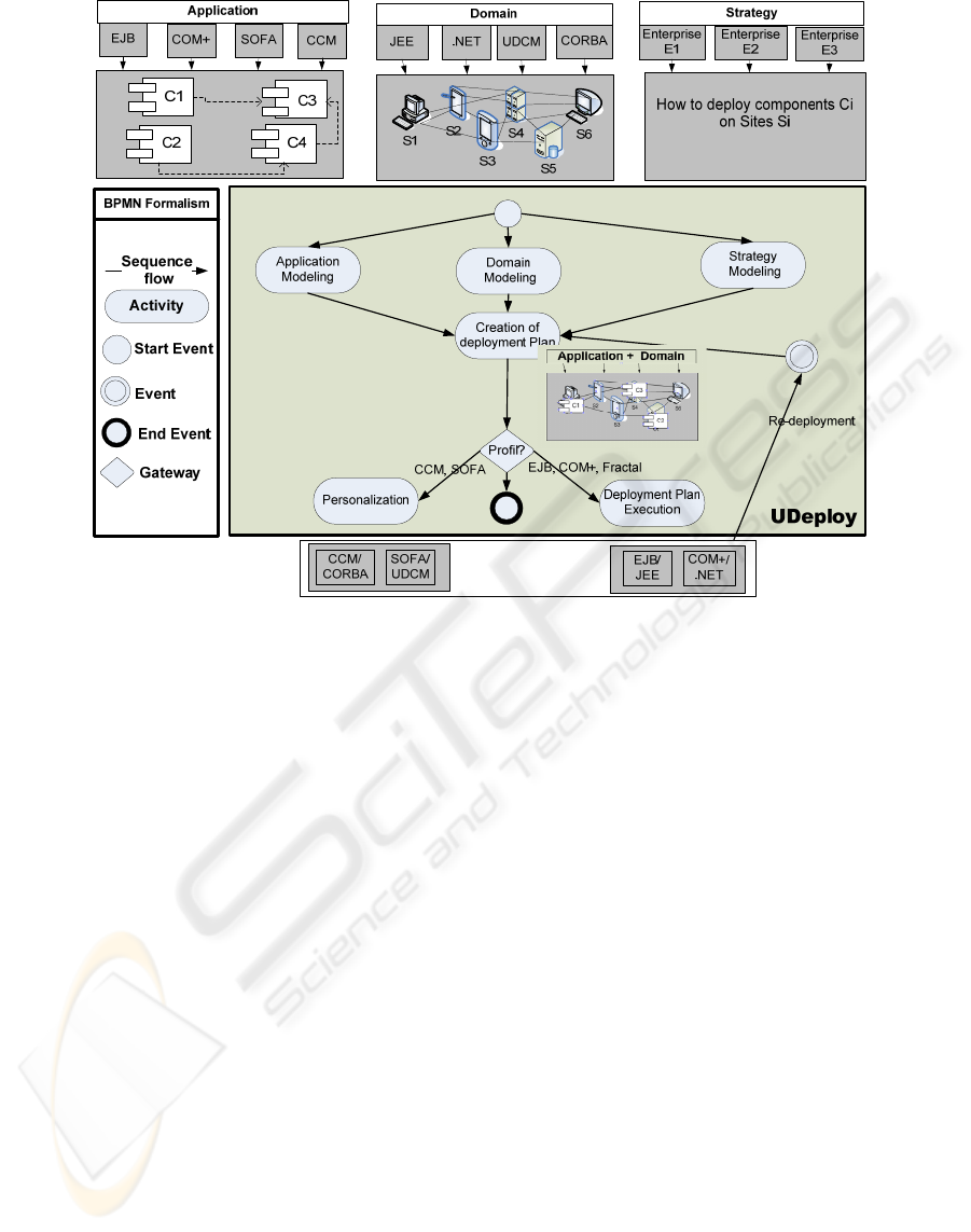
Figure 1: UDeploy Architecture.
description is based on BPMN Formalism (OMG,
2008).
UDeploy is a generic tool based on metamodels
(application, domain, strategies and plan). The plan
is computed automatically independently from a
specific technology. Then the deployment plan must
be transformed into specific plans (personalization).
To fulfil these requirements, we use the MDA
approach for model transformation.
MDA approach (OMG, 2005) was suggested by
OMG to adress the issues caused by the manifold of
computer systems, languages and technologies. The
main idea of the MDA approach is the partition of
technical concerns and business concerns. Therefore,
the approach puts forward the following two models:
PIM (Platform Independent Model), it describes
the system, but does not show details of the use of
its platform.
PSM (Platform specific Model), is a similar, but
dependent model; it also specifies how a system
makes use of the chosen platform.
The conversion PIM to PSM or PSM to PIM is
operated by model transformations. A model
transformation is defined by certain rules. These
rules can be described by using a transformation tool
such as Query View Transformation (QVT) or,
simply by implementing one’s own transformation
rules.
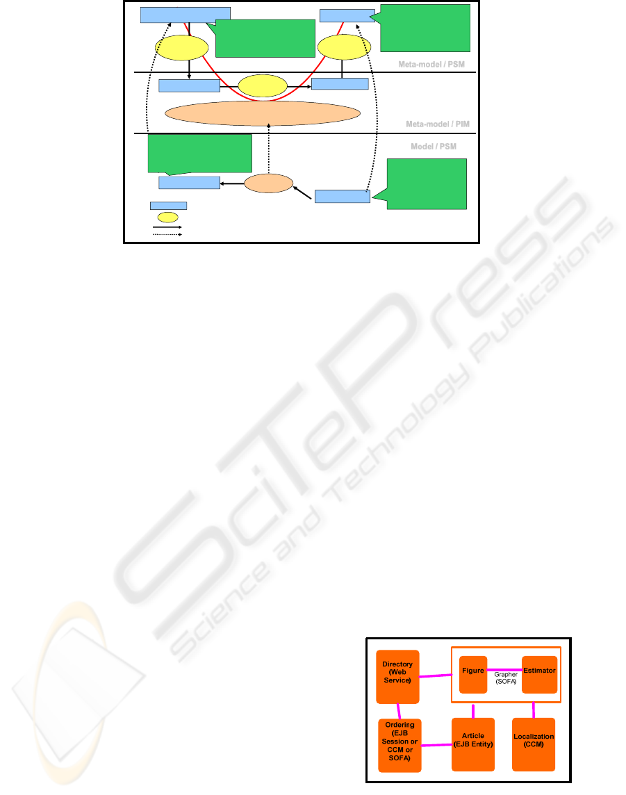
Figure 2 represents our proposition of the
automatic generation of deployment descriptor from
the transformation of models. All the
transformations occurring are:
Transformation 1: (Application Model PSM to
PIM), the application model (PSM level) is seen as
all the files and the source codes. These codes do not
interest us at the deployment level but rather their
software architectures. So, we are going to deduct by
introspection from these codes, the component meta-
information, the dependencies, the properties and the
constraints. This meta-information will be
transcribed in the application model (PIM).
Transformation 2: Domain Model PSM to PIM,
the domain model (PSM level) is seen as all the
deployment machines and servers. Generally, the
domain model is implicit (EJB.NET, CCM, SOFA).
In this case, the model transformation is not
necessary. The material architecture will be directly
described at the PIM level. When the domain model
(level PSM) is explicit as the DSD of Software
Dock. The transformation will be processed by a
transformation tool according to the typology of
transformation (Ecore to Java or DTD to Java).
Transformation 3: Deployment Plan (PIM) to
Deployment Descriptor (PSM), the deployment
descriptor is an instantiation of the deployment plan
ENASE 2010 - International Conference on Evaluation of Novel Approaches to Software Engineering
160
Meta-model / PIM
Model / PSM
Descriptor Grammar
XSD Descriptor
XMLPad
Ecore
Java Class
EMF
public class Session{
protected string home
public void setRemote(String h)
...
}
EMF
Transformation Rules
Deployment Planification/Calculus
XML Descriptor
Java Objects
home = ejbs.ArticleHome
remote = ejbs.Article
...
<?xml version="1. 0" ?>
......
<home>ejbs.Articl eH ome</ home>
<remote>ejbs.Article</r em ote>
.....
Rules
Conform to
Instance of
Conform to
<!--ejb-jar_2_0.dtd-->
…
<!ELEMENT ejb-ref (description?,
ejb-ref-name, ejb-ref-type,
home, remote, ejb-link?)>
Meta-model / PSM
File
Transformation Tools
Transformation
Conform to / Instance to
Figure 2: Deployment descriptor Generation.
for a specific platform. At the PIM level, we can
manipulate the concepts (component, node,
resource, constraint, dependency, and placement)
and create the instances. The persistence is
processed in Java for practical reasons. Once the
Java classes have been instanced, we use these data
to generate the deployment descriptor. However, the
deployment descriptor generated conforms to
specific grammar. To ensure correspondence, we use
JDOM for the transcription of Java objects in XML.
3 A DEPLOYEMENT CASE
STUDY USING UDEPLOY
3.1 Application Modeling
Our scenario model is a heterogeneous and
distributed component-based software. It allows the
management of all the supply chain of a company
selling computer hardware from parts production to
the delivery phase at the distributor or the customer
end of the process. To simplify, we called our
application LogiChaine, inspiration from "My SAP
Supply Chain Management". We distinguish five
components in LogiChaine. Each plays a specific
role in the supply chain management:
"Article", is an EJB entity component. It allows
registration of information on manufactured
products such as serial number information,
specification sheet, production date and
product location in the warehouse.
"Ordering" component exists in EJB session,
CCM and SOFA implementation. It allows the
distributor of products to place orders at the
factory or the warehouse. Every order is
identified in a unique way by the shipping
number and the registration code of the
customer who placed the order.
"Directory" is a Web service (CCM
component) of a yellow page type. It is used
by the component Grapher.
"Localization" is a CCM component, which
gives information on the geographical location
of the parcel. It uses a system of Radio
Frequency Identification (RFID) which allows
the localization of a parcel in real time.
"Grapher" is a Sofa composite, formed by two
components "Figure" and "Estimator". The
component "Estimator" estimates the likely
order time by making a calculation by entering
the geographical location of the parcel by the
component "localization" and by adding the
destination address using the yellow page
Web service "Directory". And the component
"Figure" allows the display of its information.
This feature allows the user to see the order
status in real time, at all times.
Figure 3: Application LogiChaine.
Table 1 describes for each component, the different
implementations, and the constraints of hardware
and software resources.
A GENERIC FRAMEWORK FOR DISTRIBUTED COMPONENTS-BASED SOFTWARE SYSTEMS DEPLOYMENT -
Case Study and Tool Description
161
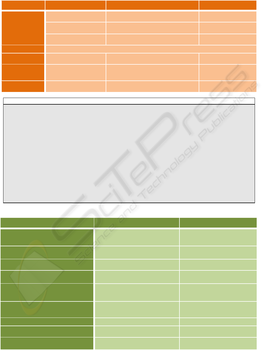
Table 1: Application model (implementations and constraints).
Component Implementations Software constraints
Hardware Constraints
Ordering
Ordering_CCM_v3
OpenOrb 1.3.1
Java Virtual Machine = JRE 1.4.2-02
Mass Storage >=2 Go
Ordering_EJB_v3
JBOSS 4.2.3.GA
Java Virtual Machine = JRE 1.4.2-02
Mass Storage >=1 Go
Ordering_SOFA_v3
SOFAruntime
Java Virtual Machine =JRE 1.4.2-02
Mass Storage >=1 Go
Directory
Directory_WSDL_v3 is already deployed in « IBM Lotus Domino »
Grapher
Grapher_SOFA_v3
SOFAruntime
Java Virtual Machine =JRE 1.4.2-02
Mass Storage >=50 M0
Article
Article_EJB_v3
JBOSS 4.2.3.GA
Java Virtual Machine = JRE 1.4.2-02
version = ORACLE 8.1.5
RAM > =3062 Mo
Mass Storage >=450 Go
localization
Lacalization_CCM_v3
OpenOrb 1.3.1
Java Virtual Machine = JRE 1.4.2-02
RAM> = 512 Mo
Mass Storage>= 72 Mo
Application.xml
<application>
<name>Logichaine</name>
<component>
<name>Article</name>
<implementation>
<implementationid>Article_EJB_v3</implementationid>
<repository>C://</repository>
<SoftwareConstraint>
<name>SN1</name>
<type> Data Server </type>
<operator>equal</operator>
<value> ORACLE 8.1.5</value>
</SoftwareConstraint>
...
</implementation>
</component>
...
</application>
Table 2: Domain model.
Site Software resource Hardware resource
H1: Application Server and Database Server
ORACLE 11g
JBOSS 4.2.3.GA
Java Virtual Machine = JRE 1.4.2-02
Mass Storage =900 G0
Mass Storage =700 Go
Processor = Core 2 Quad
H2: Application Server
OpenOrb 1.3.1
Java Virtual Machine = JRE 1.4.2-02
RAM= 3062 Mo
Mass Storage= 800 G0
H3: Application Server
SOFAruntime
Java Virtual Machine = JRE 1.4.2-02
RAM = 3062 Mo
Mass Storage= 800 G0
H4: Application Server
JBOSS 4.2.3.GA
Java Virtual Machine = JRE 1.4.2-02
RAM = 3062 Mo
Mass Storage= 700 G0
PDA1: RFID (Truck)
OpenOrb 1.3.1
Java Virtual Machine =JRE 1.4.2-02
Localization_CCM_v2
RAM = 512 Mo
Mass Storage =4 Go
Processor = Core 2 Duo
PDA2: RFID (Boat)
OpenOrb 1.3.1
Java Virtual Machine =JRE 1.4.2-02
RAM = 512 Mo
Mass Storage =10 Go
Processor = Core 2 Duo
Alice: PC
Windows Vista Processor= T9300
Sigma: Web Server
IBM Lotus Domino
Directory_WSDL_v3
Mass Storage =160 Go
Adele: Application Server
SOFAruntime
Java Virtual Machine = JRE 1.4.2-02
RAM = 3062 Mo
Mass Storage= 800 G0
ENASE 2010 - International Conference on Evaluation of Novel Approaches to Software Engineering
162
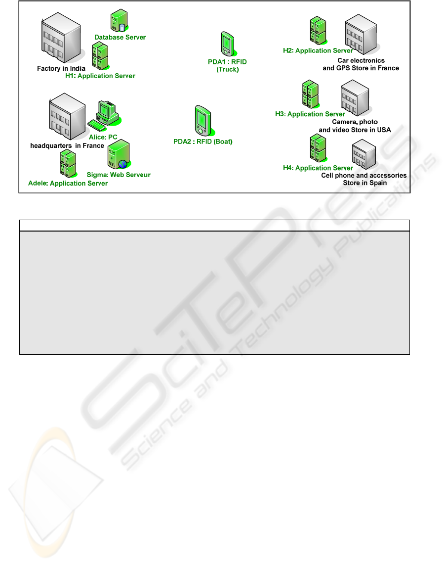
Figure 4: Deployment Domain (Enterprise Solis).
domain.xml
<domain>
<name>Solis</name>
<node>
<name>H1</name>
<ip>145.25.35.145<ip>
<SoftwareResource>
<name>SR1</name>
<type>Data Server</type>
<value> ORACLE 11g</value>
</SoftwareRessource>
</node>
...
</domain>
3.2 Domain Modeling
We wish to deploy LogiChaine in a domain Solis
formed by ten sites. On the Site PDA1 is installed
Localization
_CCM_v2 and on the Site Sigma is
installed Directory_WSDL_v3.
Table 2 describes for each site, the hardware and
software resources available.
3.3 Strategy Modeling
Deployment strategies guide the creation of the
deployment plan. A good deployment strategy
should express the technical choices and the
corporate policies. Technical choices express the
influence of both hardware and software architecture
on the software lifecycle. Corporate policies are
specific to each organization; they allow
organizations to customize deployment. Deployment
strategies are defined in accordance with the ECA
rules (Papamarkos et al., 2003): ON Event IF
Condition THEN Action. It contains one or more
ECA rules.
Two kinds of rules exist: Mandatory and
Default rules. The rules apply to the association of
the couple components-sites. The results obtained
must satisfy the constraints defined by a deploy rule.
Mandatory rules: the specified components
must be deployed on the specified sites.
Default rules: the components and the sites
specified by their attributes apply if these
components and sites exist; if not the rule has no
effect. They are only used by default and if they do
not conflict with the mandatory rules.
Event specifies the signal that triggers the
invocation of the rule (install, uninstall, update,
activate, deactivate, adapt, any).
Condition is a logical test which, if satisfied or
evaluated to true, causes the action to be carried out.
Action is a selection of specific properties when
condition is satisfied.
Selection (AttributeName, CompareOp,
AttributeValue) may specify the properties defined
A GENERIC FRAMEWORK FOR DISTRIBUTED COMPONENTS-BASED SOFTWARE SYSTEMS DEPLOYMENT -
Case Study and Tool Description
163
Deploymentstategies.xml
<DeploymentStrategies Configuration =”Strategy1”>
<ECA_rule TypeofRule=”MANDATORY”>
ON
<Event>
<Command>INSTALL</Command>
</Event>
IF
<Condition>
<Selection>
<AttributeName>Component.Assembly.type</AttributeName>
<CompareOp>=</CompareOp>
<AttributeValue>Business Assembly</AttributeValue>
</Selection>
AND
<Selection>
<AttributeName>Component.Implementation.Type</AttributeName>
<CompareOp>=</CompareOp>
<AttributeValue>EJB Entity</AttributeValue>
</Selection>
</Condition>
THEN SELECT
<Action Mode=”RA”>
<Selection>
<AttributeName>Site.ProvideResource.Type</AttributeName>
<CompareOp>=</CompareOp>
<AttributeValue>JEE SERVER</AttributeValue>
</Selection>
AND
<Selection>
...
</Selection>
</Action>
</ECA_rule>
<ECA_rule TypeofRule=”DEFAULT”>...
</ECA_rule>
...
</DeploymentStrategies>
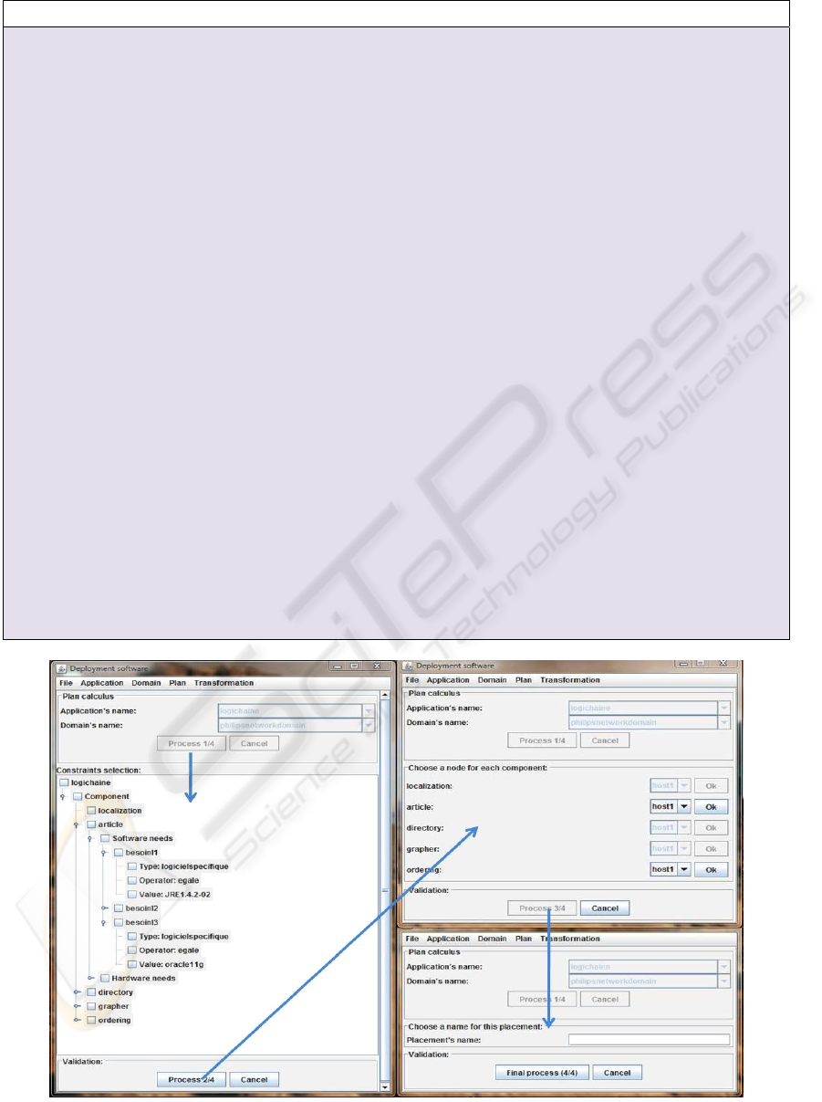
Figure 5: Computing plan.
ENASE 2010 - International Conference on Evaluation of Novel Approaches to Software Engineering
164
in the application model for the component part and
in the domain model for the site part. For the mode
part we rely on work developed by (Parrish et al.,
2001) according to the component version
compatibility defines in the application descriptor
(Replace Always RA, Replace Only If Newer ROIN,
Never Replace NR)
3.4 Plan Elaboration
The deployment plan builds itself gradually (Fig. 5).
In UDeploy, the identified functions and the chosen
organization are the following:
1) Ask the user which application, which domain
and which strategies the plan must be
calculated on.
2) Ask the user to validate the component
software and hardware constraints that must be
respected.
3) Calculate the possible associations between
components and nodes.
4) Ask the user to choose between potential
placements; when the user chooses a
placement, we return again to step 3 in order to
take in account the decrease (in number) of the
software and hardware resources for the chosen
node.
5) Ask the user to name the deployment plan.
The computing plan is an incremental process,
so to limit the errors and to facilitate the interaction,
we decided to add a graphic user interface. Our
graphic user interface is built according to the
principles of ergonomics. These criteria allow
mainly to protect against errors or to reduce user
workload.
If we compute the deployment plan from the
application LogiChaine, the domain Solis and the
deployment strategies, we will obtain the following
deployment plan:
Deploymentplan.xml
<DeploymentPlan>
<name>DeploymentPlan1</name>
<applicaton>logichaine</application>
<domaine>Solis</domain>
<placement>
<component> Article_EJB_v3</component>
<node> H1</node>
</placement>
<placement>
<component> Ordering_CCM_v3</component>
<node> H2</node>
</placement>
<placement>
<component> Ordering_SOFA_v3</component>
<node> H3</node>
</placement>
<placement>
<component> Ordering_EJB_v3</component>
<node> H4</node>
</placement>
<placement>
<component> Localization_CCM_v3</component>
<node> PDA1</node>
</placement>
<placement>
<component> Localization_CCM_v3</component>
<node> PDA2</node>
</placement>
<placement>
<component> grapher_SOFA_v3</component>
<node> Adele</node>
</placement>
</ DeploymentPlan>
3.5 Personalization
By personalizing the deployment plan, we obtain the
following plans for specific technologies:
For CCM MIDDLEWARE
On H2 Deployment Descriptor DD1 is
Install (Ordering_CCM_v3)
On
PDA1 Deployment Descriptor DD2 is
Remove (Localization _CCM_v2)
Install (Localization _CCM_v3)
--- strategy is RA (Replace Always)---
For SOFA MIDDLEWARE
<depl-plan name="DD3" component=
"
Grapher_SOFA_v3">
<depl-subc name=" Figure"
node="Adele">
<depl-subc name=" Estimator"
node="Adele">
</depl-plan>
<depl-plan name="DD4" component=
"
Localization_SOFA_v3">
<depl-subc name="Localization"
node="Adele">
</depl-plan>
CCM Middleware and SOFA Middleware take
care directly of the execution of the deployment
plans – respectively DD1, DD2 for CCM and DD3,
DD4 for SOFA.
A GENERIC FRAMEWORK FOR DISTRIBUTED COMPONENTS-BASED SOFTWARE SYSTEMS DEPLOYMENT -
Case Study and Tool Description
165
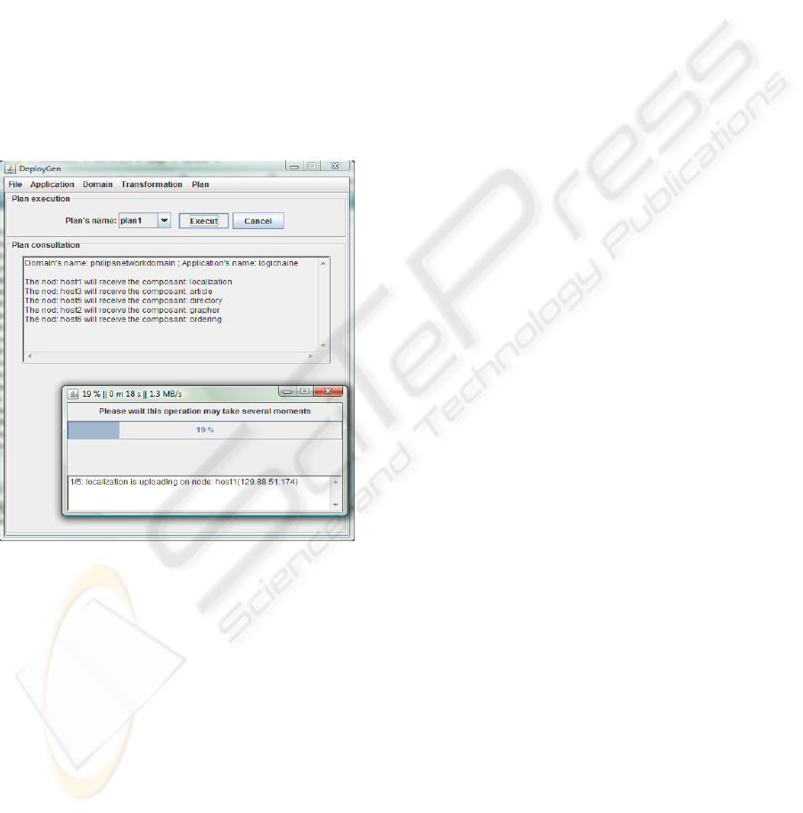
3.6 Deployment Plan Execution
If the component technology is EJB, COM+, Fractal,
then we execute in target middleware. For EJB
middleware, we must provide the deployment plan
to the JEE server. Since the JEE application server
installed on H1and H4 is JBoss, the following plan
must be executed (in JBoss).
Deployment Descriptor DD5 is
On H1 twiddle invoke
"jboss.system:service=
MainDeployer" deploy
file:
article_EJB_v3.jar
On H4
twiddle invoke
"jboss.system:service=
MainDeployer" deploy
file:
ordering_EJB_v3.jar
Figure 6: Deployment plan execution.
4 CONCLUSIONS
AND PERSPECTIVES
We develop Udeploy a prototype based on MDA
approach which ensures tree main tasks:
(i) it manages the planning process from meta-
information related to the application, the
infrastructure and the deployment strategies,
(ii) it generates specific deployment descriptors
related to the application and the environment
(i.e. the machines connected to a network
where a software system is deployed) and
(iii) it executes a deployment plan.
We have positive feedback with our case study
and its experimentation on EJB, .NET and CCM
platforms. Our current projects include carrying out
other experiments and evaluations to show the
feasability of the approach, for example its
application to industrial systems, .NET and CCM.
REFERENCES
Alliance, O. (2005). OSGi 4.0 release. Specification
available at http://www.osgi.org/.
Bures, T., Hnetynka, P., and Plasil, F. (2006). Sofa 2.0:
Balancing advanced features in a hierarchical
component model. In SERA, pages 40–48. IEEE
Computer Society.
Clements, P. C. (1996). A survey of architecture
description languages. In IWSSD ’96: Proceedings of
the 8th International Workshop on Software
Specification and Design, page 16, Washington, DC,
USA. IEEE Computer Society.
Dibo, M. and Belkhatir, N. (2009). Challenges and
perspectives in the deployment of distributed
components-based software. In ICEIS(3), pages 403–
406.
Dibo, M. and Belkhatir, N. (2010a). Defining an unified
meta modeling architecture for deployment of
distributed components-based software applications.
In ICEIS.
Dibo, M. and Belkhatir, N. (2010b). Model-driven
deployment of distributed components-based software.
In ICSOFT.
Dochez, J. (2009). Jsr 88: Java enterprise edition 5
deployment api specification. Available at http://
jcp.org/aboutJava/communityprocess/mrel/jsr088/inde
x.html.
Edwards, G. T., Deng, G., Schmidt, D. C., Gokhale, A. S.,
and Natarajan, B. (2004). Model-driven configuration
and deployment of component middleware
publish/subscribe services. In GPCE, pages 337–360.
Gustavo, A., Fabio, C., Harumi, K., and Vijay, M. (2004).
Web Services: Concepts, Architecture and
Applications.
OMG (2006a). Corba component model 4.0. Specification
available at http://www.omg.org/docs/formal/06-04-
01.pdf.
OMG (2006b). Deployment and configuration of
component-based distributed application. Specification
available at http://www.omg.org.
OMG, T. O. M. G. (2005). Omg model driven
architecture. Available at http://www.omg.org.
OMG, T. O. M. G. (2007). Unified modeling language.
Available at http://www.omg.org.
OMG, T. O. M. G. (2008). Business process modeling
notation (bpmn) v1.1. Available at http://
www.omg.org.
Papamarkos, G., Poulovassilis, A., Poulovassilis, R., and
Wood, P. T. (2003). Event-condition-action rule
languages for the semantic web. pages 309–327.
ENASE 2010 - International Conference on Evaluation of Novel Approaches to Software Engineering
166

Parrish, A., Dixon, B., and Cordes, D. (2001). A
conceptual foundation for component-based software
deployment. J. Syst. Softw., 57(3):193–200.
Szyperski, C., Gruntz, D., and Murer, S. (2002).
Component Software: Beyond Object-Oriented
Programming. Addison-Wesley Professional. 2nd
Edition, England.
Troelsen, A. (2008a). Chapter 1: The Philosophy of .NET,
volume Pro VB 2008 and the .NET 3.5 Platform.
APress.
Troelsen, A. (2008b). Chapter 15: Introducing .NET
Assemblies, volume Pro VB 2008 and the .NET 3.5
Platform. APress.
A GENERIC FRAMEWORK FOR DISTRIBUTED COMPONENTS-BASED SOFTWARE SYSTEMS DEPLOYMENT -
Case Study and Tool Description
167
