
MODEL-BASED SERVICE INTEGRATION FOR EXTENSIBLE
ENTERPRISE SYSTEMS WITH ADAPTATION PATTERNS
Markus Heller and Matthias Allgaier
SAP Research, Vincenz-Priessnitz-Str. 1, 76131 Karlsruhe, Germany
Keywords Service Integration, Service Ecosystems, Business Application Extensibility, SOA, Web Services.
Abstract: The integration of services into business applications within enterprise services is needed in on-premise
settings as well as in upcoming on-demand enterprise settings. Today, it is typically performed in manual
integration projects by highly skilled integration experts on the consumer side. As consumers demand
flexible and adaptable enterprise systems with lower total cost of ownership (TCO), enterprise system
vendors need to provide efficient mechanisms to integrate services within business applications. For this
less explored but promising area of service-oriented architecture (SOA) research, a service integration
framework with a pattern-based modeling approach is presented that allows for the integration of services
into business applications at a later stage in the software-lifecycle - especially after shipment.
1 INTRODUCTION
In the vision of an Internet of Services, organizations
in a service ecosystem (Barros and Dumas, 2006)
interact in service provider and/or consumer roles to
offer, find, trade, and use services like tradable
goods
. A key challenge for enterprise organisations
will be to ensure simple consumption of their
offered services via multiple channels (e.g.
composite applications, mash-up applications). An
important channel handles service consumption
within standard business applications running within
enterprise systems (e.g. ERP, CRM, or others). Such
systems typically realize implemented standard
business processes and it is very valuable to be able
to extend them with complementary services after
the system has been shipped. Such services can be
provided by other organizations as service
ecosystem partners and offered in service
marketplaces or service stores. A less-complex
integration of services becomes particular relevant
for service/partner ecosystems in upcoming on-
demand enterprise software environments (Lo et al.,
2009). Two main integration scenarios can be
differentiated to achieve the integration of a service
into an enterprise system. First, existing interfaces
of the enterprise system are used to integrate the
service. This is possible, if the system provider has
foreseen such interfaces at time of shipment.
Prominent examples for this first alternative are
standard interfaces for Business-to-Business (B2B)
or Application-to-Application (A2A) integration
scenarios for Enterprise Application Integration
(EAI). Second, if a service cannot be integrated into
a business application using foreseen interfaces, the
enterprise system has to be extended and/or adapted
on affected internal application layers beforehand.
For example, new UI elements (presentation layer),
process steps (process layer), or business object
fields
(business object layer) can be created or
existing elements adapted in the application.
Examples are services offered by multiple providers
for different core or niche business domains. In both
integration scenarios structural- and/or behavioural
mismatches between the service interfaces of the
enterprise system and the service provider need to be
handled by service mediation components.
Three main deficits are noted for the second
integration scenario: (i) The adaptation or extension
of an enterprise system usually requires a high
manual effort and high level of expertise. (ii) Today,
enterprise
systems provide adaptation or extension
mechanisms which typically are proprietary
solutions on low abstraction level (e.g. code-level
interfaces). Similarly, for different application layers
typically different adaptation and extension
techniques are offered. (iii) Typically, deep domain
or technical knowledge is required to oversee and
implement the integration solution.
In this paper a service integration framework is
proposed for unforeseen service integration into core
163
Heller M. and Allgaier M. (2010).
MODEL-BASED SERVICE INTEGRATION FOR EXTENSIBLE ENTERPRISE SYSTEMS WITH ADAPTATION PATTERNS.
In Proceedings of the International Conference on e-Business, pages 163-168
DOI: 10.5220/0002994301630168
Copyright
c
SciTePress
business applications with the observed
deficits (scenario 2). It enables partners in a service
ecosystem to seamlessly integrate new services into
business applications within enterprise systems at a
later stage in the software-lifecycle. This work
applies the design science research
methodology (Hevner et al., 2004). Section 2
describes an application scenario from the
automotive industry. Section 3 introduces the service
integration framework. Related work is described in
Section 4. Summary and outlook are given in
Section 5.
2 APPLICATION SCENARIO
In the automotive domain, due to legal changes in
export guidelines, a manufacturer of car seats needs
to certify his products to guarantee that materials
used in a car seats are compliant with ecological
laws. On a service marketplace, a service provider
offers a service for the calculation of eco values for
products including certification. The manufacturer
runs an enterprise system including a Product-
Lifecycle-Management (PLM) module for the
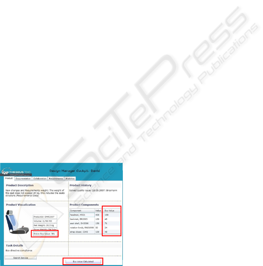
design process support for car seats (Figure 1). In its
core version, this business application does not
support eco value calculation for a given bill of
material. Therefore, a product designer of the
manufacturer company searches the Service
Marketplace directly from within his enterprise
system to find services that provide the missing
functionality. He receives a list of matching services
from various service providers certified for his
Figure 1: Extension of a PLM business application.
enterprise system. The designer selects and buys a
service called “Eco-Calculator” on the marketplace.
This remote service is automatically integrated into
the core business application (without the need to
run a manual integration project). The user interface
of the core business application is extended with (1)
a new table column (“Eco Value”) in the product
components table, (2) a new button (“Calculate Eco
Value”) and (3) a new field to display the total eco
value for the car seat (“Entire Eco Value”). The
service is used by the designer immediately after the
integration has been completed. If the total eco value
fulfils legal requirements, a certificate is generated
for the seat and passed to the consumer application.
3 SERVICE INTEGRATION
FRAMEWORK
A discussion of the requirements for the framework
development is presented in (Allgaier and Heller,
2009). The service integration framework is based
on the following characteristics: (1) A model-based
integration approach is introduced to enable the
modeling (or design) of the relevant integration
aspects on a higher abstraction level. (2) A pattern-
based modeling approach is defined that covers
typical adaptation- and extension tasks. It allows
controlled extensibility of the core business
applications, insofar, as only a proven set of
adaptation operations can be performed. This
approach provides a uniform approach to enable
service integrators to design the adaptation and
extension of a core business application on multiple
layers (e.g. UI- and business process layer). (3) To
increase the level of automation for service
integration, a seamlessly integrated runtime support
for extension and/or adaption of enterprise systems
completes the framework. This paper describes the
(visual) modelling language, while the internal
realization of the framework meta model is
described in (Allgaier, Heller, and Weidner, 2010).
3.1 Overview and Main Components
Figure 2 shows the main components of the service
integration framework: Integration Modeling
Environment (top), Adaptation-/Extension Exe-
cution Environment (middle), and Enterprise
System (bottom). (1) As a prerequisite, the enter-
prise system provider creates and delivers an
Enterprise System to run different Core Business
Applications. These business applications are used
by end users. The enterprise system is connected to
the Adaptation/Enactment Execution Environment
to allow for adaptation and extension of the system
after initial shipment at a later stage in the software-
ICE-B 2010 - International Conference on e-Business
164
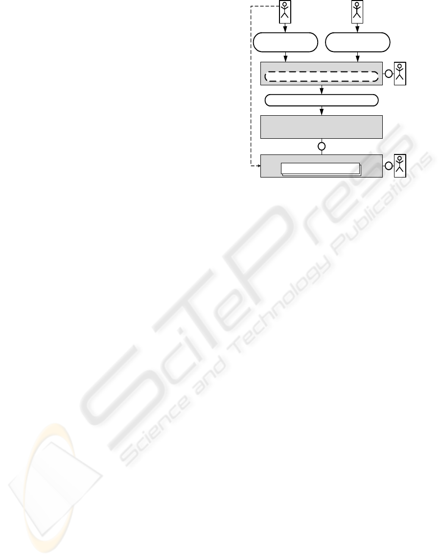
lifecycle. The enterprise system provider publishes
an Application Extensibility Description (left) that
represents the core business application’s
extensibility capabilities within the enterprise
system. Similarly, the service provider creates a
Service Description (right) for a service that he
offers, e.g. on a service marketplace. The Service
Description describes multiple aspects of the
service’s capabilities.
(2) The service integrator uses the Integration
Modeling Environment to model all relevant aspects
to define an integration of a selected service into a
selected core business application within an
enterprise system (based on a loaded application
extensibility description and a loaded service
description). All modeled information about the
integration is stored in an Integration Model data
structure within the modeling environment. This
model specifies all adaptation and/or extension steps
to achieve the desired integration.
(3) When all details have been completely
specified, the Integration Modeling Environment
creates an Integration Description (middle) that can
be loaded into the Adaptation/Extension Execution
Environment. This component orchestrates all
necessary steps for the adaptation and extension of
the core business applications and enterprise system.
An Enterprise System (e.g. ERP system) is
described with a single overall abstracted model that
spans across four abstraction layers. Basically an
enterprise system consists of multiple (service-
based) Business Applications that leverage a
common service and business configuration layer.
The Service Layer contains all services offered by
the enterprise system. Core services provide access
to business objects and they can be composed into
larger bundles to provide advanced higher-value
business functionality or application logic. The
Business Configuration Layer contains the
configuration data for the business applications with
all of its available customization options.
For a business application, the Presentation
Layer comprises all artifacts and components for the
user interface part of the business application (for
example, UI components for a dedicated UI platform
with all interrelations). Likewise, the Process Layer
contains models of the business processes which are
realized within a business application. Modeling
elements for business processes can contain
references to elements on other layers such as
presentation or service layer.
To adapt standard business applications to
customer specific needs, enterprise systems typically
provide a large set of proprietary extensibility resp.
adaptability features (as e.g. in SAP’s ByDesign On-
Demand platform). The features support a wide
Figure 2: Service Integration Framework Components.
spectrum of use cases and address various
stakeholders for flexibility requirements like
customers (e.g. extensibility or flexibility as
customer self-service), verticalization and globali-
zation, or partners in software eco systems.
3.2 Layered Modeling Approach
The mentioned central model artefacts in the
framework are detailed as follows: (a) The
Application Description contains all possible
extension points where the application can be
extended or adapted. Such extension points model
the offered extensibility features of the application
on top of the underlying enterprise system. For
example, extension points denote places in the
application that can be used to add a process step to
a core process or a new UI, and so on. (b) The
Service Description contains meta-data information
about the service and all information needed for its
integration into business applications (such as
service operations with input and output interfaces,
supported data types, messaging choreographies,
offered default UI descriptions). (c) The Integration
Description contains as a dominant part a set of
connections between elements the application
extensibility description and the service description
as well as additional parameterization data. It can
additionally reference any combinations of software
artifacts needed for the Adaptation/Extension
Execution Environment to perform the service
integration.
Application description, integration description,
and service description (shown horizontally in
Figure 3 in the columns from left to right) are
modeled on two different modeling layers (shown
vertically). The Technical Model Layer (bottom
Service
Provider
Service
Integrator
Enterprise
System
Provider
Integration Modeling Environment
Adaptation/Extension Execution Environment
Integration Model
Enterprise System
Application Extensibility
Description
Service Description
Integration Description
Core Business Application
Output
Input
delivers
Input Input
createscreates
User
MODEL-BASED SERVICE INTEGRATION FOR EXTENSIBLE ENTERPRISE SYSTEMS WITH ADAPTATION
PATTERNS
165
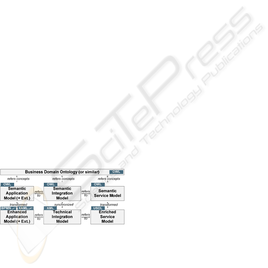
part) contains models to describe applications or
services with respect to their extensibility support.
Standard Models (like e.g. XAML, BPMN) lack
necessary modeling elements (for example, to model
extension points). Therefore, they need to be
enhanced on the technical model layer with new
extensibility concepts. The Enhanced Application
Model represents a complete description of an
extensible application. It comprises all kinds of
models describing the extensibility support of the
application on different application layers.
Presentation or process models (XAML, BPM, etc.)
are enhanced with additional new elements to model
extension points and extension connection models
(e.g. as in the BPMN 2.0 proposal draft). The
Enriched Service Model (e.g. in USDL) contains
modeling elements from a service model (like
WSDL) plus new elements to describe further
service capabilities like supported business
application details. The Technical Integration Model
holds all connections between elements from
Enhanced Application Model and Enriched Service
Model with parameterizations.
The Semantic Model Layer (top part) contains
ontology representations of the models from the
Technical Integration Layer. For this purpose,
relevant elements from models on the Technical
Model Layer are transformed into ontological
representations on the Semantic Model Layer. A
Semantic Application Model semantically captures
important model concepts from the Technical
Application Model (with extensibility support).
Likewise, the Semantic Service Model and the
Semantic Integration Model are constructed from the
models on the Technical Layer.
Figure 3: Technical and semantic modeling layers.
Some of the models on both layers can reference
entities of further ontologies (top part) that model
important business domain concepts, like in
Business Domain Ontologies (BDO), e.g. from the
SUPER research project. Within the framework, the
Technical Models (as Ecore models) are used
together with the Semantic Models (as OWL
ontologies) which primarily serve for reasoning over
the model semantics for searches in model data and
advanced modeling guidance support. In the rest of
this paper, the semantic models are used. They are
valuable for advanced semantic search functionality
to recommend best fitting application extension
points or service elements for ports of used pattern
instances in the modeling environment.
3.3 Pattern-based Modeling
The integration modeling language is based on the
notion of adaptation pattern. They allow to restrict
which integration steps are performed to control the
flexibility of the enterprise system. (Atomic)
Adaptation Patterns define typical fine-grained
adaptation or extension tasks that can be performed
on the application layers. Adaptation Patterns
represent parameterizable connection links between
extension points of the application description and
elements of the service description. The patterns
have a set of application or service reference ports
and a set of further parameterization attributes. An
application reference port links the pattern to an
application extension point (of a predefined type),
while a service reference port links the pattern to a
service description element (of a predefined type).
Parameterization attributes store further key-value
pairs within the pattern context.
Complex adaptation patterns are composed of
atomic and/or other complex adaptation patterns and
they model more coarse-grained extension tasks for
typical multi-step integration scenarios, e.g. across
different application layers. Atomic and composite
patterns are stored in a knowledge base called
adaptation pattern catalog and they can be reused
within many integration designs by different service
integrators (best-practice sharing). The set of stored
adaptation patterns can be collected, extended, and
revised based on other related work, e.g. (Weber,
2008) for possible pattern candidates or by creating
previously unknown patterns (e.g. an adaptation
pattern editor tool is currently under development).
During the modeling phase, an integration model
instance is created in the modeling environment by
the service integrator and extended step-wise by first
choosing an (complex or atomic) adaptation pattern
from a catalog and adding it to the current
integration model. Second, the pattern’s ports are
connected to chosen application extension points or
service description elements.
An example from the Eco Calculator scenario in
Section 2 illustrates the modeling approach.
The service integrator wants to define the
integration of the Eco Calculator service (found on
the service marketplace) into a business application.
ICE-B 2010 - International Conference on e-Business
166
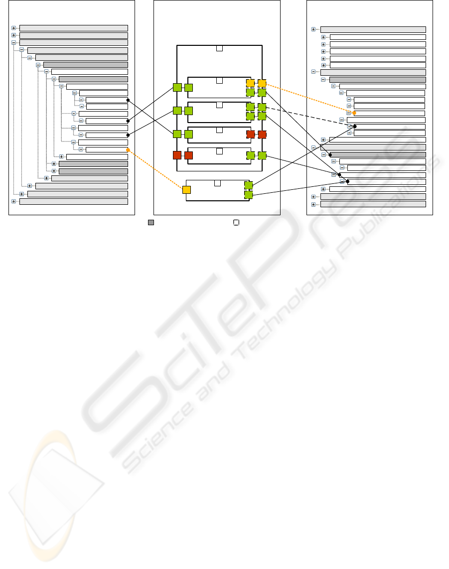
Figure 4: Example Integration Model for the Integration of the EcoCalculator service into the PLM business application.
No interface was foreseen for this use case in the
enterprise system at shipping time. The service
integrator identifies the following requirements (e.g.
from a business department): The service should be
integrated into the Product-Lifecycle-Management
(PLM) part of the enterprise system. The service
should be used before the product (car seat) is
shipped. The eco values returned from the service
should be displayed on the user interface in the
existing table to display the bill of material elements
for the car seat. The returned eco values should only
be displayed on the user interface.
Figure 4 shows integration model (middle),
application description (left) for the PLM
application and service description (right) for the
EcoCalculator service. The model contains one
complex adaptation pattern instance and another
atomic adaptation pattern instance with their
parameterizations. The complex pattern “Stateless
Service Integration without data persistency” was
chosen because it technically seems to fit to the
given business requirements to integrate the service
on UI layer and service layer: It allows for adding a
stateless service (with one operation), adding a UI
button and display labels into UI panels. The result
data of the service is not persisted in the enterprise
system. The modeled complex pattern contains four
atomic adaptation patterns: (i) addButton, (ii)
addTableColumn, (iii) addDataMeditator and (iv)
addDataMediator. The complex adaptation pattern
carries four application reference ports (A1, A2, A3,
and A4) and six service reference ports (A5, A6, A7,
A8, A9, and A10) that are internally linked to the
ports of the contained atomic adaptation patterns.
Some ports are parameterized with application’s
extension points or service description elements. For
example, for the chosen application “Product
Engineering”, some extension points of the UI
component “UC1” are connected to the application
ports (A1, A2, A3, and A4) of the shown adaptation
patterns and some service elements are connected to
the service ports (A5, A6, A7, A8, A9, and A10).
The adaptation pattern “addButton” is connected
via the application reference port B1 with the port
type Extension Point Type – Button Panel. This port
is parameterized with the value BP-EP#1. The text
for the button is taken from the Default User
Interface section of the service description (service
reference port B2). The information for the button’s
event handler (service operation that is called when
the button is pressed) is taken from the Operations
section of the service description (service reference
port B3). The pattern “addDataMediator” models a
data mediation problem which is resolved via
externally executed data mediation tools. Finally, a
new integration description (referencing application
description and service description) is generated
from the modeling environment.
3.4 Runtime Extensibility Support
An implemented prototype demonstrates the
feasibility of the proposed approach to service
integration for the application scenario of Section 3.
The PLM business application is implemented based
on Microsoft Silverlight, the EcoCalculator Web
Stateless UI Service
Integration without
Data Persistency
Business Aspects
Default User Interface
Operations
Operation: calculateEcoValue
Input Interface
Output Interface
Service Choreography Description
Operation: calculateEcoValue
Panel: Main Container
Input Area
Label: Material Description
Text Input: BOM
Button: Calculate Eco Value
...
Output Area
Label: Eco Value
Text Output: Eco Values
Element: BOM
List Element : Eco Values
...
...
addButton
-
B2
B3
addTableColumn
-
C2
C3
-
addDataMediator
-
D2
addDataMediator
-
E2
Functionality
Classification
Pricing / Service Level
Security
A5
A6
A7
A8
A9
A10
addOutputField
-
F2
F3
...
Integration Design Model
Product Lifecycle Management
Product Management
Product Dev. and R&D Collaboration
Business Applications
Product Engineering
UI Components
UC 1
Button Panel – BP1
Table – T1
Panel – P1
...
Process Components
Services
...
...
...
Customer Relationship Management
Enterprise Ressource Planing
...
EP – P-EP#3
EP – T-EP#2
EP – BP-EP#1
B1
C1
D1
E1
Data Interface
Import Interface
Export Interface
A1
A2
A3
A4
F1
Service Description ModelApplication Extensibility Description
Model
Legend Application Reference Port Service Reference Port
MODEL-BASED SERVICE INTEGRATION FOR EXTENSIBLE ENTERPRISE SYSTEMS WITH ADAPTATION
PATTERNS
167

Service uses the AXIS framework. The prototype
addresses the presentation layer. Figure 5 shows its
architecture. An integration description is loaded
into the Adaptation/Extension Execution Environ-
ment (Java). It analyzes each adaptation step in the
description and forwards it to a layer-specific
adaptation manager, here for UI- and service-layer.
They adapt the PLM application, for example, for
the UI-layer adaptation by calling a sequence of
commands at the native extensibility features API
(MS Silverlight API) at runtime. The screenshot in
Figure 1 on page 4 shows the prototype after
extension with a new button, a new table column,
and a new output label. Not visible in the UI, two
data mediators are added to map data between the UI
context and the service interface.
4 RELATED WORK
This work addresses the controlled extensibility of
enterprise systems for unforeseen service
integration, similar to related B2B Integration and
Enterprise Application Integration, e.g. (Hophe and
Woolf, 2003). Structural or behavioural interface
mediation techniques, e.g. (Studer et al., 2007), are
leveraged in the framework, e.g. for data mediation.
Work on adaptive software systems typically
addresses self-adaptive systems for mobile,
pervasive computing (e.g. MADAM, http://www.ist-
madam.org). Plug-in techniques for development
and installation of (downloaded) components into
component-based core application frameworks,
e.g. (Birsan, 2005), or for runtime adaptation of ERP
systems, e.g. (Wolfinger et al., 2008), do not target
unforeseen service integration. Extensions on the
presentation layer leverage adaptive user interface
modeling approaches (e.g. XIML, UIML). Process
change patterns, e.g. by (Weber et al., 2008),
provide a conceptual basis for the process layer
adaptation pattern catalog in this paper.
5 SUMMARY AND OUTLOOK
A model-based service integration framework for
the unforeseen integration of services into extensible
enterprise systems has been presented. In the
author’s opinion, the promising service integration
area should be further investigated. The modeling
approach with adaptation patterns and runtime
support is demonstrated with a UI integration
prototype in the automotive domain. The Process
layer support is currently developed.
Figure 5: Runtime support architecture.
ACKNOWLEDGEMENTS
The work presented in this paper is embedded into
THESEUS/TEXO project funded by means of the
German Federal Ministry of Economy and
Technology under prom. reference 01MQ07012.
Authors take the responsibility for the content.z
REFERENCES
Allgaier M. and Heller M. (2009) Research Challenges for
Seamless Service Integration in Extensible Enterprise
Systems, Workshop “Industrial Experiences for
Service Oriented Computing”. Stockholm, Sweden.
Allgaier M., Heller M., and Weidner M. (2010) Towards a
Model-based Service Integration Framework for
Extensible Enterprise Systems, in: M. Schumann, L.
M. Kolbe, M. H. Breitner (Eds.): Tagungsband der
Multikonferenz Wirtschaftsinformatik, Göttingen.
Barros A. and Dumas M. (2006) The Rise of Web Service
Ecosystems. IT Professional, 8, 5, 31-37.
Birsan D. (2005) On Plug-ins and Extensible Architetures.
Queue, 3, 2, 40-46.
Hevner A.R., March S.T., Park J., and Ram S. (2004)
Design Science in Information Systems Research. MIS
Quarterly, 28, 1, 75-105.
Hohpe G. and Woolf B. (2003) Enterprise Integration
Patterns - Designing, Building, and Deploying
Messaging Solutions. Addison-Wesley Prof., Boston.
Lo H., Wang R., and Garbini, J.P. (2009) The State of
Enterprise Software 2009. Forrester, Cambridge.
Studer R., Grimm S., and Abecker A. (2007) Semantic
Web Services. Springer, Berlin.
Weber B., Reichert M., and Rinderle-Ma S. (2008)
Change patterns and change support features -
Enhancing flexibility. DKE, 66, 3, 438-466.
Wolfinger R., Reiter S., Dhungana D., Grünbacher P., and
Prähofer H. (2008) Supporting Runtime System
Adaptation through Product Line Engineering and
Plug-in Techniques. In: 7th IEEE International
Conference on Composition-Based Software
Systems (ICCBSS’08), Madrid.
Integration Description
Adaptation/Extension Execution Environment
PLM Business Application (Microsoft Silverlight)
UI Adaptation Manager
Enterprise System Extensibility Features (API)
parameterize
adapt
Artefacts
generates
deploy
...
User
Adaptation
Patterns
Application
Layer
Add
Button
UI-Layer
Parameterization
P1: Application Extensibility Model EP - BP-EP#1
P2: Button Text: Calculate Eco Value
P3: Event Handler: Call Service „Calc. EcoValue“
Step
1
ICE-B 2010 - International Conference on e-Business
168
