
WEB SERVICES FOR HIGHER INTEGRITY
INSTRUMENT CONTROL
Philip R. Huffman
B&W Pantex, LLC, Amarillo, TX, U.S.A.
Susan A. Mengel
Texas Tech University, Computer Science, Lubbock, TX, U.S.A.
Keywords:
Software integrity, Web services.
Abstract:
This paper relates the experience in using a modified life cycle development process which is proposed herein
for integrity planning applied to web services as reusable software components in order to enhance the web
services’ reliability, safety, and security in an instrument control environment. Using the integrity-enhanced
lifecycle, a test bed instrument control system is developed using .NET web services. A commercial web
service is also included in the test bed system for comparison. Both systems are monitored over a one-
year period and failure data is collected. For a further comparison, a similar instrument control system is
developed to a high quality pedigree but lacking the focus on integrity and reusable components. Most of
the instrumentation is the same between the two systems; however, the comparative system uses a more
traditional approach with a single, integrated software control package. As with the test bed system, this
comparative system is monitored over a one-year period. The data for the two systems is compared and the
results demonstrate a significant increase in integrity for the web service-based test bed system. The failure
rate for the test bed system is approximately 1 in 8100 as compared to 1 in 1600 for the comparison system.
1 INTRODUCTION
In this paper, high integrity software is defined as hav-
ing a requisite level of safety, security, and/or relia-
bility that must be defined prior to starting a project
and measured as a standard to be attained. Intuitively,
the prospect of a “black box” software module like
web services, exercised under a wide variety of con-
ditions on multiple systems should have a more ro-
bust measure of its true level of safety, reliability, and
security. Indeed, the current state of software reuse
technologies has progressed from software objects,
to components, to web services, which are demon-
strating great potential for such distributable, reusable
“black box” software modules (Yang and Papazoglou,
2002). One shortfall of reusable software modules
may be the lack of pedigree on the delivered product.
This paper proposes that the addition of planning and
a good development process helps to establish that
missing pedigree at delivery, that integrity in the com-
ponent. With integrity established, reusable software
modules, such as web services, may be used to en-
hance the safety, reliability, and security in a software
package.
2 INTEGRITY
This paper defines integrity as a combination of
safety, reliability, and security. Reliability focuses on
the specific capabilities of a given component: will
the component meet its specification over some pe-
riod of time under defined conditions? Safety and
security focus on how the component interacts with
the total system. One cannot assess a software com-
ponent (or any type of component) in a vacuum and
make a statement about its integrity without consid-
ering these interactions. To do so can produce a very
unreliable system that is very safe, or a highly reliable
system that may still jeopardize someone’s safety. A
literature search has found effort focused on software
safety improvements (Leveson, 2004) (Parnas et al.,
1990) (Storey, 1996) (Wilson et al., 1995) or security
151
R. Huffman P. and A. Mengel S. (2010).
WEB SERVICES FOR HIGHER INTEGRITY INSTRUMENT CONTROL.
In Proceedings of the 5th International Conference on Software and Data Technologies, pages 151-156
DOI: 10.5220/0002983701510156
Copyright
c
SciTePress

in the information technology environment (Chang
and Atallah, 2001) (Wyk and McGraw, 2005) or re-
liability improvement in software (Herrmann, 1999)
(SAE, 2004) (Keene, 1999) (Lakey and Neufelder,
1997).
For safety-related software, Parnas and associates
(Parnas et al., 1990) focus on disciplined design, doc-
umentation, testing and review. Mathematical nota-
tion is recommended over natural language structures,
and independence is required of the reviewers. Thor-
ough testing make up the third leg of their propos-
als to enhance safety. Wilson and associates (Wil-
son et al., 1995) propose development of supporting
evidence for attaining safety goals. For better relia-
bility, JA1003 (SAE, 2004) proposes including relia-
bility techniques in the software engineering frame-
work and developing supporting evidence for relia-
bility goals. Chang and associates (Chang and Atal-
lah, 2001) have proposed methods to protect program
integrity and enhance security by multiple security
modules. It is proposed to use each of these con-
cepts to create higher integrity software modules in
the form of web services.
3 DEVELOPMENT PROCESS
FOR INTEGRITY
The specific process model used in this paper is an
internal company model closely related to ISO/IEC
15504 and IEEE/IEC 12207. This model is aug-
mented to focus on integrity, using ideas from the
safety case and reliability case proposals discussed
previously (SAE, 2004) (Parnas et al., 1990).
As the software process begins, a new document,
the software integrity plan, is started and developedin
parallel with the software while the software require-
ments are derived from the system design specifica-
tions and include the safety, reliability, and security
criteria. Those requirements that are integrity-related
are identified and used to develop a requirements
tracking database. This database is used through the
design stage, into the code development, and through
verification/validation activities. Software safety, re-
liability, and security are analyzed and graded by pre-
determined criteria, and those grades are used to de-
termine the degree of scrutiny imposed on each soft-
ware deliverable.
The software design process uses UML and for-
mal notation to assure requirements are tracked into
design and into validation. Specific modules are con-
sidered as guards for software security, and redun-
dant services are considered to meet reliability cri-
teria. Design artifacts are captured and traceability
is formally verified between each development stage.
A software causal analysis is performed to determine
potential failure modes of the final software design.
Once implemented into code, the software is sub-
ject to formal review and interface analysis. Testing
is performed to a high level of coverageand includes
requirements testing, functionality testing, fault in-
jection, and performance testing. Finally, the design
team brainstorms potential abnormal events and “rare
events” testing to complete the test suite. The in-
tegrity plan mentioned previously does not capture
the detail of the testing, but does document that test-
ing is performed. Testing detail is captured in the soft-
ware (and system) validation plan(s) and qualification
activities are captured in the software (and system)
qualification plan(s). Traceability is also captured and
demonstrated in the integrity plan through traceability
matrices.
Deployed into its production environment, quali-
fication reviews are performed on the software and a
subset of the test suite is used to validate the software
with the customer and other interested parties. Each
software artifact is verified and traceability is demon-
strated throughout the entire process. Qualification
review results are captured in the qualification plan,
but completion of the qualification activities is docu-
mented in the integrity plan.
3.1 The Software Integrity Plan
The integrity plan consists of four major sections.
The first section provides project-specific informa-
tion, governing criteria, and the project scope. Section
two addresses the project management activities, nor-
mally by pointing to a separate project management
plan. Specifically, integrity management can point to
the other project artifacts for such management prac-
tices as development, resources, configuration con-
trol, and software quality assurance. Section three
addresses preliminary integrity analyses and grading.
This section also provides additional detail to flow
system hazards and system risk criteria down as the
starting point for the software integrity process. Sec-
tion four follows each stage of the enhanced-integrity
life cycle development process. Separate subsections
address the development activities for each of the as-
sociated life cycle phase practices, but from an in-
tegrity position. For instance, at the requirements
stage, those requirements that are integrity related are
identified and used to develop a requirements track-
ing database. This database is added to the plan and is
part of the resulting evidence package. Likewise, the
design stage focuses on flow down from the integrity-
related requirements and assures that any integrity-
ICSOFT 2010 - 5th International Conference on Software and Data Technologies
152
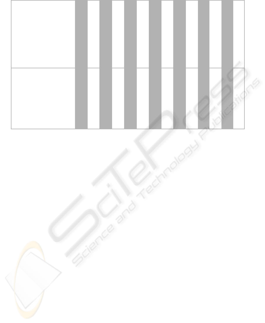
Table 1: Overview of Development Process for .NET Services.
Service
Requirements Development
Traceability Analysis
Requirements Review
Design Development
Design Analyses
Traceability Analysis
Design Review
Code Implementation
Code Analysis
Traceability Analysis
Code Review
Validation Testing
Validation Data Review
Certification/Archival
Valve Controller X X X X X X X X X X X X X X
Vacuum Gauge X X X X X X X X X X X X X X
Micrometer X X X X X X X X X X X X X X
Pressure Gauge X X X X X X X X X X X X X X
Leak Detector X X X X X X X X X X X X X X
Motion Controller X X X X X X X X X X X X X X
Temperature Analyzer X X X X X X X X X X X X X X
Drill/Weld Controller X X X X X X X X X X X X X X
Drill Analyzer (Comm.) ? ? ? ? ? ? ? ? ? ? ? ? ? ?
related design methodology applied to the specific de-
sign is captured and credited. The final subsections of
the life cycle process include document qualification
and certification activities, with checklists and refer-
ences to software artifacts. The results coming from
the integrity plan may be used to make the argument,
the “integrity case,” for the software stating that the
software meets its integrity criteria throughout its life
(Wilson et al., 1995).
4 TEST BED
The test bed system, the Enhanced Integrity Test Bed
(EIT), is an instrumentation control system that per-
forms an automated drilling operation into a high-
value product, extracts a sample, and welds the sam-
ple hole closed. The Comparative Sampling System
(CSS), also performs an automated drilling opera-
tion into a high-value product, performs a sampling
operation, and welds the sample hole closed. Most
of the instrumentation is the same between the two
systems; however, the comparative system uses tra-
ditional structured programming with a single, inte-
grated software executive.
The completed software product for the EIT con-
sists of the main system executive and nine reusable
.NET services each running on one of nine embedded
computers that communicate with a system control
computer running the executive software. Of these
services, eight are designed in-house by multiple de-
velopers according to the enhanced-integrity develop-
ment process described previously, with the inherent
artifacts, reviews, analyses, and test activities as sum-
marized in Table 1. The eight services were devel-
oped using Visual Studio .NET and range in size from
1,000 lines of code to 10,000 lines of code. The sys-
tem executive is approximately 25,000 lines of code.
Five of the services and the system executive were de-
veloped by the first author, with the remaining three
developed by three other developers on the team. The
ninth service is a commercially-available service, a
drill analyzer, which was selected as a comparison to
the eight services developed in-house. This service
has only the commercial operations guide and its de-
veloper’s manual documenting its interface; however,
as a commercial product available for three years, it
was postulated that this service has had the opportu-
nity to be refined through customer feedback.
Specific to the EIT, each web service is intended
to be available for use on multiple systems. Each ser-
vice is a model of the instrument it controls. The
instrument control manual is treated as a system de-
sign specification from which the service’s software
requirements are derived.
The architectural design of the CSS follows a
more traditional design methodology with all in-
struments interfaced to the central control computer.
Likewise, the software is designed as a single ex-
ecutive that manages and controls each instrument,
manages the test sequences, performs data flow and
pass/fail testing, and provides the interface to the user.
While the CSS system does not incorporate the in-
tegrity enhancements to its development model, its
development follows a comprehensive quality model
WEB SERVICES FOR HIGHER INTEGRITY INSTRUMENT CONTROL
153
with emphasis on safety considerations. The software
for the CSS was developed traditionally, by a team of
two developers, and is approximately 75,000 lines of
mixed high-level and assembly-level code.
5 TEST BED EVALUATION
The EIT was initially deployed in an open setup en-
vironment for its first nine months of operation. Fol-
lowing this, the software product was installed on the
production system and operated for a period of three
months.
Each day begins on the EIT by performing a sys-
tem warm up operation, followed by a calibration of
the leak detector, and daily system verification. The
daily verification allows the collection of data on each
web service regardless of the number of production
runs, which may vary from none to five runs on any
given day.
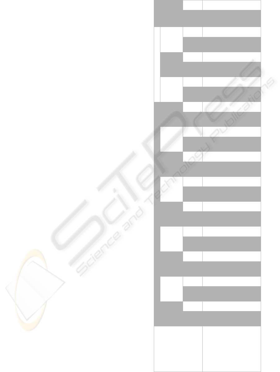
A monthly compilation of the total operational cy-
cles for each service in the test bed system has been
prepared for both the open setup deployment and the
production system, and is presented in Table 2. A
cycle is defined as a call and a response to a web ser-
vice through its defined interface and is not represen-
tative of the inner operations of the service. By using
this definition, the service is treated as a black box
component. From these results, two observations are
readily apparent: 1) the most well exercised service
has only been run for about 50,000 cycles, well below
the threshold necessary to declare a high reliability
value based on empirical results; and 2) with a fail-
ure rate of about 1 in 30 cycles, the commercial web
service is showing lower reliability than the services
developed in-house with a focus on integrity. Analy-
sis of the failure mechanism has determined that each
failure for this service occurred during its startup. By
using an administrative control in the system startup
procedure, no additional failures have occurred in the
last two months of operations.
As expected, the data from a single system would
require years to collect the necessary data for pub-
lishing empirical reliability values for a web service.
Even the most exercised service on the test bed, the
valve controller, would require over 20 years at the
current rate (44,000 cycles/year) to reach a docu-
mented failure rate of less than 1 in 1e6 operations, a
fairly standard value for high reliability components.
However, use of the services on multiple copies of the
system or on multiple systems does appear promising
to develop real failure rate data. Two of these ser-
vices, the vacuum gauge service and the valve con-
troller service, have recently been adopted for use on
Table 2: Summary of Operations and Failure Count for Test
Period for the EIT.
Benchtop System Production System
Month 1
Month 2
Month 3
Month 4
Month 5
Month 6
Month 7
Month 8
Month 9
Month 10
Month 11
Month 12
Documented
Failures
Web Service
Operations
Failures
Operations
Failures
Operations
Failures
Operations
Failures
Operations
Failures
Operations
Failures
Operations
Failures
Operations
Failures
Operations
Failures
Operations
Failures
Operations
Failures
Operations
Failures
Operations
Failures
Days Operational 23 - 20 - 23 - 21 - 16 - 23 - 21 - 17 - 20 - 16 - 13 - 15 - 228 -
Valve Controller 5599 0 5510 0 3569 0 2987 0 2436 0 2931 0 4785 0 4669 0 3480 0 3364 0 2523 0 2349 0 44202 0
Vacuum Gauge 168 0 170 0 98 0 82 0 68 0 76 0 144 0 144 0 100 0 100 0 74 0 66 0 1290 0
Micrometer 580 0 600 0 300 0 244 0 208 0 212 0 492 0 508 0 320 0 336 0 244 0 204 0 4248 0
Pressure Gauge 267 0 290 0 127 0 101 0 88 0 83 0 225 0 237 0 140 0 152 0 109 0 87 0 1906 0
Leak Detector 130 0 125 0 95 0 83 0 66 0 84 0 114 0 105 0 90 0 82 0 63 0 63 0 1100 0
Motion Controller 794 0 810 0 444 0 368 0 308 0 334 0 678 0 686 0 460 0 468 0 344 0 300 0 5994 0
Temperature Analyzer 366 0 390 0 156 0 120 0 108 0 90 0 306 0 330 0 180 0 204 0 144 0 108 0 2502 0
Drill/Weld Controller 1450 0 1500 0 750 0 610 0 520 0 530 0 1230 0 1270 0 800 0 680 0 610 0 510 0 10460 0
Drill Analyzer (Comm) 168 1 170 1 98 0 82 0 68 1 76 0 144 2 144 0 100 3 100 1 70 0 66 0 1286 9
ICSOFT 2010 - 5th International Conference on Software and Data Technologies
154
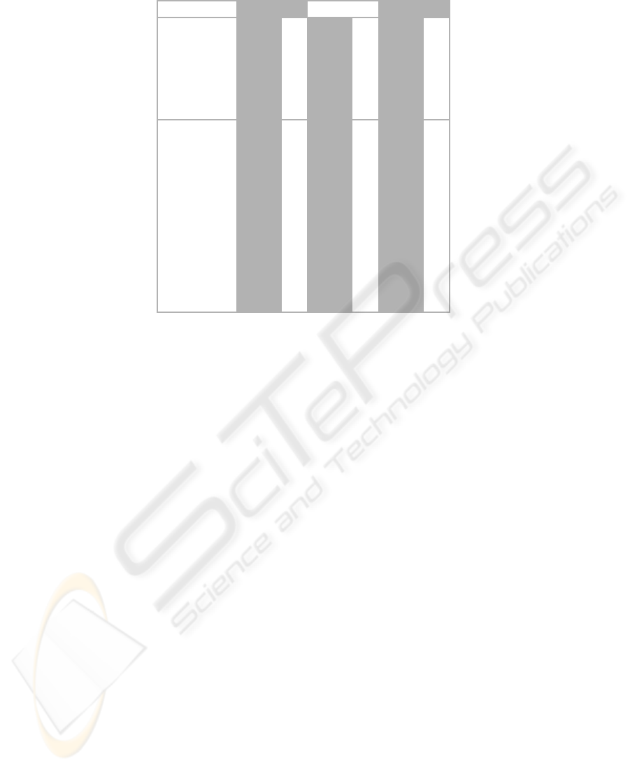
Table 3: Summary of Operations and Failure Count for Test Period for the CSS.
Copy 1 Copy 2 Total
Cycle Data
Operations
Failures
Operations
Failures
Total Operations
Total Failures
Month 1 1938 3 2166 1 4104 4
Month 2 570 1 2280 1 2850 2
Month 3 - - 2508 1 2508 1
Month 4 - - 2280 0 2280 0
Month 5 - - 2052 0 2052 0
Month 6 - - 1824 1 1824 1
Month 7 - - 2280 0 2280 0
Month 8 - - 1026 2 1026 2
Month 9 456 1 - - 456 1
Month 10 1710 2 - - 1710 2
Month 11 684 0 - - 684 0
Month 12 570 1 - - 570 1
another production system of differing design allow-
ing multiple platform data collection to develop addi-
tional empirical data in the near future.
5.1 CSS Evaluation
Two copies of the CSS have operated for the same
twelve-month period as the EIT in a production envi-
ronment. The first copy has run for approximately
eight months of the year and the second copy for
about four months. Also, the CSS is somewhat sim-
pler than the EIT, lacking three of the instruments
in the EIT: the micrometer, the temperature analyzer,
and the drill analyzer.
Each day begins with a system warm up operation,
calibration of the leak detector, and a daily self test.
Each system performs a number of process runs, vary-
ing from none to two on a given day. Unlike the EIT,
no log service exists to allow for tracking of opera-
tion cycles in a manner similar to the EIT. The data
runs that are used for comparative data analysis are
only those obtained from actual production runs, as
these are manually documented. Warm up, calibra-
tion, and daily self test runs are not documented for
the CSS and, therefore, are not included in the com-
parative data.
For the CSS, a cycle is defined as the execution of
an instrument call. By parsing the CSS control soft-
ware; a subroutine is identified corresponding to each
EIT web service by function. Calls from the executive
routine to these subroutines are treated as equivalent
to a call/response cycle on the EIT for comparative
data analysis.
The two CSS stations have operated for approxi-
mately one year with approximately 22,350 combined
documented cycles (reference Table 3). During this
time period, fourteen failures were recorded during
process runs. The resulting failure rate is about 1
in 1600, about five times greater than the EIT failure
rate.
5.2 Conclusions
The final failure rate for the CSS is approximately1 in
1600 operations. The total failure rate for the EIT is
approximately 1 in 8100. When discounting the com-
mercial drill analyzer, not present in the CSS, the EIT
has almost 75,000 operations with no failures. The
commercial drill analyzer web service has a failure
rate of almost 1 in 30. The empirical data supports
the conclusion that the integrity enhancements to the
development process and the use of trusted web ser-
vices result in a higher integrity end product.
Demonstration of this methodologyhas been com-
pleted through the use of a test bed system based on
integrity web services. Thus far, all integrity services
have operated with no failures over the course of the
first year of operation. The test bed is treated as a
black box system, focusing on the reusable services
for enhanced integrity. A comparison system devel-
oped with similar methodology, but without the fo-
cus on reuse, was also monitored over the course of a
year. The test bed application has shown superiority
in integrity for the limited data collected thus far, with
WEB SERVICES FOR HIGHER INTEGRITY INSTRUMENT CONTROL
155

a failure rate of approximately 1 in 8100, potentially
greater than 1 in 75,000, as compared to 1 in 1600 for
the comparison system.
REFERENCES
Chang, H. and Atallah, M. (2001). Protecting software code
by guards. In ACM CCS-8 Workshop on Security and
Privacy in Digital Rights Management, pages 160–
175.
Herrmann, D. (1999). Software Safety and Reliability. IEEE
Computer Society.
Keene, S. (1999). Progressive software reliability model-
ing. In International Symposium on Software Relia-
bility Engineering.
Lakey, P. and Neufelder, A. (1997). System and Software
Reliability Assurance Notebook. McDonnell Douglas
Corporation.
Leveson, N. (2004). A systems-theoretic approach to safety
in software-intensive systems. IEEE Transactions on
Dependable and Secure Computing, 1(1):66–86.
Parnas, D., van Schouwen, A., and Kwan, S. (1990). Eval-
uation of safety critical software. Communications of
the ACM, 33(6):636–648.
SAE (2004). SAE JA Guideline 1003: Software Reliability
Program Standard Implementation Guide. Society of
Automotive Engineers.
Storey, N. (1996). Safety-Critical Computer Systems. Pren-
tice Hall.
Wilson, S., Kelly, T., and McDermid, J. (1995). Safety case
development: Current practice, future prospects. In
Proceedings Of the 12th Annual CSR Workshop.
Wyk, K. V. and McGraw, G. (2005). Bridging the gap be-
tween software development and information security.
IEEE Security and Privacy, 3(5):75–79.
Yang, J. and Papazoglou, M. (2002). Web component:
A substrate for web service reuse and composition.
In Proceedings of the 14th International Conference
on Advanced Information Systems Engineering, pages
21–36.
ICSOFT 2010 - 5th International Conference on Software and Data Technologies
156
